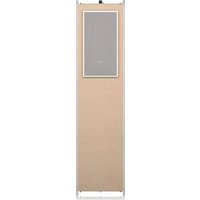
PCI SUB IW WITH BACK CAN - Loudspeaker TANNOY - Free user manual and instructions
Find the device manual for free PCI SUB IW WITH BACK CAN TANNOY in PDF.


| Product Type | In-wall Speaker / In-wall Subwoofer |
| Brand | Tannoy |
| Model | PCI SUB IW WITH BACK CAN |
| Category | Subwoofer |
| Number of Speakers | 2 drivers |
| Installation Type | In-wall (with back can or direct cutout) |
| Frame Material | Polycarbonate (clamping tabs) |
| Connection Type | Screw terminals (+/-) |
| Recommended Wiring | Insulated speaker wire 12-18 AWG |
| Included Accessories | Paint mask, cutout template, hex screws (6) |
| Operating Temperature | Max 45 °C (tropical or moderate climate) |
| Cleaning | Dry cloth |
| Safety | Do not open, repair by qualified professional only |
| Warranty | Limited, see musictribe.com/warranty |
| Intended Use | Indoor |
| Disposal | Do not dispose with household waste, WEEE recycling |
| Reference | PCI SUB IW WITH BACK CAN |
Frequently Asked Questions - PCI SUB IW WITH BACK CAN TANNOY
User questions about PCI SUB IW WITH BACK CAN TANNOY
0 question about this device. Answer the ones you know or ask your own.
Ask a new question about this device
Download the instructions for your Loudspeaker in PDF format for free! Find your manual PCI SUB IW WITH BACK CAN - TANNOY and take your electronic device back in hand. On this page are published all the documents necessary for the use of your device. PCI SUB IW WITH BACK CAN by TANNOY.
USER MANUAL PCI SUB IW WITH BACK CAN TANNOY
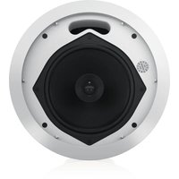
PCI In-Wall Subwoofer
PCI SUB IW
Premium Dual 8" In-Wall Subwoofer for Installation Applications
BACK CAN PCI SUB IW
Back Can Kit for PCI SUB IW In-Wall Speakers
EN
ES
FR
DE
PT
IT
NL
SE
PL
2 PCT Staff Quick Start Guide 3
EN
ES
EN Important Safety Instructions

Terminals marked with this symbol carry electrical current of sufficient magnitude to constitute risk of electric shock. the only high quality professional speaker tables with 15" TS or twist-locking plugs pre installed. All other installation or modification should be performed only by qualified personnel.
This symbol, wherever it appears, alerts you to the presence of uninsulated dangerous voltage inside the enclosure - voltage that may be sufficient to constitute a risk of shock.
This symbol, wherever it appears, alerts you to important operating and maintenance instructions in the accompanying literature. Please read the manual.
Caution To reduce the risk of electric shock, do not remove the top cover (or the rear section). No user serviceable parts include. Refer servicing to qualified personnel.
Caution To reduce the risk of fire or electric shock, do not expose this appliance to rain and moisture. The apparatus shall not be exposed to dripping or splashing liquids and no objects filled with liquids, such as wares, shall be placed on the apparatus.
Caution These service instructions are for use by qualified service personnel only. To reduce the risk of electric shock do not perform any servicing other than that contained in the operation instructions. Repairs have to be performed by qualified service personnel.
- Read these instructions.
- Keep these instructions.
- Here all warnings.
- Follow all instructions.
- Do not use this apparatus near water.
- Clean only with dry cloth.
- Do not lock any ventilation openings, install in accordance with the manufacturer's instructions.
-
Do not install near any heat sources such as rotators, heat registers, stoves, or other apparatus (including amplifiers) that produce heat.
-
Do not defeat the safety purpose of the polarized or grounding-type plug. A polarized plug has two blades with one wider than the other. A grounding-type plug has two blades and a third grounding proing. The wide blade or the third proing are provided for your safety. If the provided plug does not fit into your outlet, consult an electrician for replacement of the obsolete outlet.
-
Protect the power card from being walked on or pinched particularly at plugs, convenience receptacles, and the point where they exit from the apparatus.
- Use only attachments/accessories specified by the manufacturer.

- Use only with the cart, stand, tripod, bracket, or table specified by the manufacturer, or sold with the apparatus. When a cart is used, use caution when moving the cart/apparatus combination to avoid
injury from tip-over
-
Unplug this apparatus during lightning storms or when unused for long periods of time.
-
Refer all servicing to qualified service personnel. Servicing is required when the apparatus has been damaged in any way, such as power supply cord or plug in damaged, liquid has been spilled or objects have fallen into the apparatus, the apparatus has been exposed to rain or moisture, does not operate normally, or has been dropped.
-
The apparatus shall be connected to a MUNG socket outlet with a protective earthing connection.
-
Where the MAINS plug or an appliance coupler is used as the disconnect device, the disconnect device shall remain readily operable.

- Correct disposal of this product: This symbol indicates that this product must not be disposed at with household waste, according to the WEE Directive (2012/19/EU) and
should be taken to a collection center formed for the recycling of waste electrical and electronic equipment (EEL). The misunderstanding of this type of waste could have a possible negative impact on the environment and human health due to potentially hazardous substances that are generally associated with EEL. At the same time, your cooperation in the correct disposal of this product will contribute to the efficient use of natural resources. For more information about where you can take your waste equipment for recycling, please contact your local city office, or your household waste collection service. 18. Do not install in a confined space, such as a book case or similar unit.
-
Do not place naked flame sources, such as lighted candles, on the apparatus.
-
Please keep the environmental aspects of battery disposal in mind. Batteries must be disposed-of at a battery collection point.
-
This apparatus may be used in tropical and moderate climates up to 45°C.
LEGAL DISCLAIMER
Music Tribe accepts no liability for any loss which may be suffered by any person who relies either wholly or in part upon any description, photograph, or statement contained herein. Technical specifications, appearances and other information are subject to change without notice. All trademarks are the property of their respective owners. Midas, Clark Teknik, Lab Suggers, Luke, Tammy, Turbosound, TC Electronic, TC Helicon, Behringes, Sugera, Cherhelim, Murataone, Aston Microphones and Cootudio are trademarks or registers trademarks of Music In The Global Brands Ltd. © Music Tribe Global Brands Ltd. 2021 All rights reserved.
LIMITED WARRANTY
For the applicable warranty terms and conditions and additional information regarding Music Tribe's Limited Warranty, please see complete details online at musictribe.com/warranty.
ES
∴ m = 3/11
[Non-Text]
[Table_Title]
ES
[Non-Text]
[Non-Text]
[Non-Text]
[Non-Text]
[Non-Text]
[Non-Text]
[Non-Text]
[Non-Text]
[Non-Text]
[Non-Text]
[Non-Text]
[Non-Text]
[Non-Text]
[Non-Text]
[Non-Text]
[Non-Text]
[Non-Text]
[Non-Text]
[Non-Text]
[Non-Text]
[Non-Text]
[Non-Text]
[Non-Text]
[Non-Text]
[Non-Text]
[Non-Text]
[Non-Text]
[Non-Text]
[Non-Text]
[Non-Text]
[Non-Text]
[Non-Text]
[Non-Text]
[Non-Text]
[Non-Text]
[Non-Text]
[Non-Text]
[Non-Text]
[Non-Text]
[Non-Text]
[Non-Text]
[Non-Text]
[Non-Text]
[Non-Text]
[Non-Text]
[Non-Text]
[Non-Text]
[Non-Text]
[Non-Text]
[Non-Text]
[Non-Text]
[Non-Text]
[Non-Text]
[Non-Text]
[Non-Text]
[Non-Text]
[Non-Text]
[Non-Text]
[Non-Text]
[Non-Text]
[Non-Text]
[Non-Text]
[Non-Text]
[Non-Text]
[Non-Text]
[Non-Text]
[Non-Text]
[Non-Text]
[Non-Text]
[Non-Text]
[Non-Text]
EN
∴ m = 3/11
[Non-Text]
1
[Non-Text]
[Non-Text]
[Non-Text]
[Non-Text]
[Non-Text]
[Non-Text]
[Non-Text]
[Non-Text]
[Non-Text]
[Non-Text]
[Non-Text]
[Non-Text]
[Non-Text]
[Non-Text]
[Non-Text]
[Non-Text]
[Non-Text]
[Non-Text]
[Non-Text]
[Non-Text]
[Non-Text]
[Non-Text]
[Non-Text]
[Non-Text]
[Non-Text]
[Non-Text]
[Non-Text]
[Non-Text]
[Non-Text]
[Non-Text]
[Non-Text]
[Non-Text]
[Non-Text]
[Non-Text]
[Non-Text]
[Non-Text]
[Non-Text]
[Non-Text]
[Non-Text]
∴ m = 3/11
[Non-Text]
1
ES
∴ m = 3/11
[Non-Text]
[Non-Text]
[Non-Text]
[Non-Text]
[Non-Text]
[Non-Text]
[Non-Text]
[Non-Text]
[Non-Text]
[Non-Text]
[Non-Text]
[Non-Text]
[Non-Text]
[Non-Text]
[Non-Text]
[Non-Text]
[Non-Text]
[Non-Text]
[Non-Text]
[Non-Text]
[Non-Text]
[Non-Text]
[Non-Text]
[Non-Text]
[Non-Text]
[Non-Text]
[Non-Text]
[Non-Text]
[Non-Text]
[Non-Text]
[Non-Text]
[Non-Text]
[Non-Text]
[Non-Text]
广力云
ES
-
[Non-Text]
[Non-Text]
[Non-Text]
[Non-Text]
[Non-Text]
[Non-Text]
[Non-Text]
[Non-Text]
[Non-Text]
[Non-Text]
[Non-Text]
[Non-Text]
[Non-Text]
[Non-Text]
[Non-Text]
[Non-Text]
[Non-Text]
[Non-Text]
[Non-Text]
[Non-Text]
[Non-Text]
[Non-Text]
[Non-Text]
[Non-Text]
4 PCT Star W Quick Start Guide 5

BESCHRÄNKTE GARANTIE
Thank you for purchasing this Tammy premium dual 8" wall mount subsector for installation applications and the pre-construction wood back can installation kit, tammy speaker systems are monitor-quality speaker systems based on the company's expertise in the manufacture of premium quality cabinet loudspeakers and studio monitors. Exclusive drive unit designs and wide bandwidth technology ensure that these loudspeakers deliver the performance that is essential for applications such as multi-room distributed audio installations, home theatre systems and discrete audio systems, as well as in the many other applications where space is at a premium but ultimate sound quality is still paramount. The speaker construction is based around a rigid moulded ABS baffle with excellent structural integrity; this, when combined with the secure polycarbonate clamp mounting system, ensures a performance enhancing rigid acoustic coupling with the wall surface, and an immensely stable platform for the drivers to deliver optimum performance. Complementing any style of decor, the perforated metal grille and low profile mounting frame can be painted to blend in seamlessly with the domestic environment. The result is a system offering audiophile quality sound with minimal invasion of the living space.
Unpacking
Every Tannoy product is carefully inspected before shipment. After unpacking, please inspect your product to ensure no damage has occurred in transit. In the unlikely event of damage, please notify your dealer and retain all shipping materials as your dealer may require return shipment.
Safety Notices
Tannoy will not be held responsible for any damages caused by the improper installation of these loudspeakers.
Introducción
Product Feature Identification Product Feature Identification
Grille Installed Subwoofer and Frame Assembly
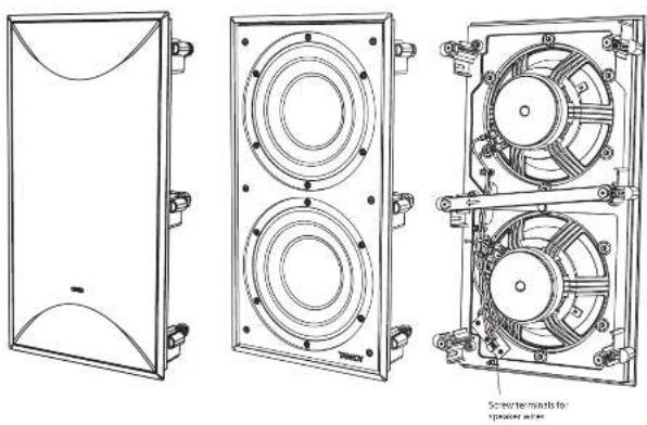
Subwoofer Assembly
Installation Template

Paint Mask
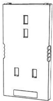
Back Can Assembly
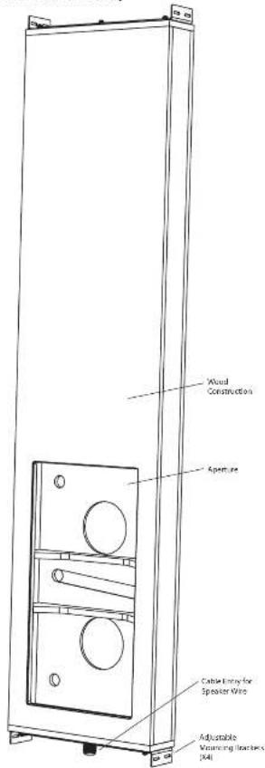
Installation Guide
Back Can Installation
WARNING: This procedure requires the use of an assistant, and the use of personal protection equipment, such as safety glasses and gloves.
WARNING: To avoid potential damage to your loudspeaker, ensure that the power amplifier is switched OFF prior to connecting or disconnecting any cables.
WARNING: Make sure that there are no power lines, other cables, or plumbing such as water, sewer, gas lines in the chosen location.
The procedure below describes the installation of the back can into a typical 2" x 4" stud wall with 16" centers, with sheetrock/plasterboard not yet installed.
After the back can and sheetrock is installed, the PCI SUB subwealer frame can be installed, and the paint mask added.
The subwoofer assembly can be wired and added after the wall painting and finishing is complete.
Procedure
Follow the procedure steps below in the order in which they are presented. Read all the instructions before starting.
-
Locate a suitable mounting position for the subwoofer that will offer optimum acoustic performance for the listening environment and audio system, and that is also practical and aesthetically pleasing.
-
With the help of an assistant, carefully move the back can to the chosen location between the wall studs, and lift it to the correct height, allowing enough room for the speaker wire to enter the bottom cable gland, and with enough room to tighten the screws that hold the brackets to the back can (Fig. 1).
-
Make sure that the front face of the back can is flush with the front face of the wall studs.
-
Adjust the sliding brackets of the back can to fit the width between the studs (Fig.2).
-
Make sure that the back can is plumb and level, then screw the 4 brackets to the wall studs using 2 screws per bracket. Tighten the screws holding the brackets to the back can.
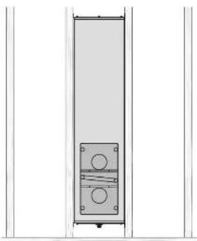
Fig. 1 Install the Back can between the studwork
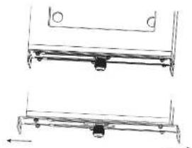
Fig. 2 adjust the sliding brackets to touch the studs on either side.
Quick Star Guide
- install the speaker wire in through the cable gland, and leave enough slack to make the connections to the subwoofer assembly when that time comes (Fig. 3). Tighten the cable gland, and tie down the speaker cable to prevent it meeting and rattling in operation. Make sure that the speaker cable does not come into contact with nails or screws that might damage the insulation.
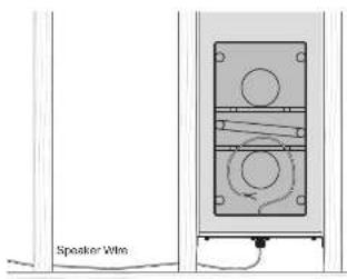
Fig. 3. Speaker Wire Installation
- The installation of sheetrock around the back can location is best done using a single large sheet with the vertical center line centered over the back can vertical centerline (Fig. 4). Use adhesive on the wall studs and on the front face of the back can, and install the sheetrock using sheetrock screws into the wall studs, spaced approximately 8 to 10 inches apart. This will help prevent wall rattling and sheetrock movement and noises during operation. If the back can is being installed on an interior wall, then adhesive and extra screws may also be added to the sheetrock used in the room behind the back can. CAUTIONL: Make sure that no sheetrock screws go into the wooden case of the back can at any point.
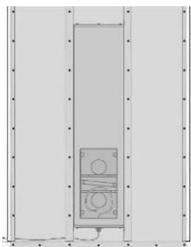
Fig. 4. Sheetrock Screws.
- After sheetrock installation, carefully cut out the hole in the sheetrock with a suitable handtool, using the subwoofer aperture in the back can as a guide (Fig. 5). Be careful not to cut the speaker wires. Make sure the sheetrock aperture is no larger than the aperture of the back can. Remove any dust or debris from within the back can.
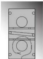
Fig. 5. Sheetrock Removed from the Aperture.
18 PCI SUB IV/
Quick Star Guide
19
Alternative Installation without the Back Can
If you are not using the PCI SUB back can, then use the supplied template as a guide to cutting the sheetrock.
WARNING: This procedure requires the use of personal protection equipment, such as safety glasses and gloves.
WARNING: To avoid potential damage to your loudspeaker, ensure that the power amplifier is switched OFF prior to connecting or disconnecting any cables.
WARNING: Make sure that there are no power lines, other cables, or plumbing such as water, sewer, gas lines in the chosen location.
The procedure below describes an installation in a typical 2' x 4" stud wall with 16' centers, with sheetrock/plasterboard already installed.
After the sheetrock aperture is cut, the PCI SUB subwoofer frame can be installed, and the paint mask added.
The subwoofer assembly can be wired and added after the wall painting and finishing is complete.
Procedure
Follow the procedure steps below in the order in which they are presented. Read all the instructions before starting.
-
Locate a suitable mounting position for the subwoofer that will offer optimum acoustic performance for the listening environment and audio system, and that is also practical and aesthetically pleasing.
-
Make sure the template is centered between wall studs that are spaced on 16 inch centers or more. This will allow room for the wall mount damps to operate freely.
-
Apply the template to the wall, and carefully drill the sheetrock in the 4 corners of the template, using a 1/2 diameter drill. Carefully cut out the hole in the sheetrock with a suitable handtool, following the template as a guide (Fig. 6). Remove any dust or debris from within the cutout.
-
Install the speaker wire to this location, and leave enough slack to make the connections to the subwoofer assembly when that time comes (Fig.7). Tie down the speaker cable to prevent it moving and rattling in operation.
-
Use adhesive within the aperture to help secure the sheetrock to the nearby wall studs, and if possible install extra sheetrock screws approximately 8 to 10 inches apart. This will help prevent wall rattling and sheetrock movement and noises during operation. If the subwoofer is being installed on an interior wall, then adhesive and extra screws may also be added to the sheetrock used in the room behind the subwoofer.
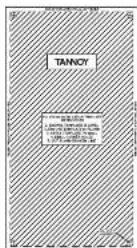
Fig. 6. Installation Template.
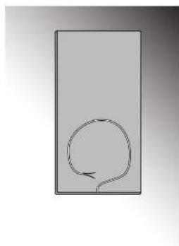
Fig. 7. Sheetrack Removed from the Aperture.
Subwoofer Frame Installation
With the back can installed and the sheetrock out as shown in the previous instructions, the speaker frame can be fitted into position. The procedure is the same if the back can is used or not.
Procedure
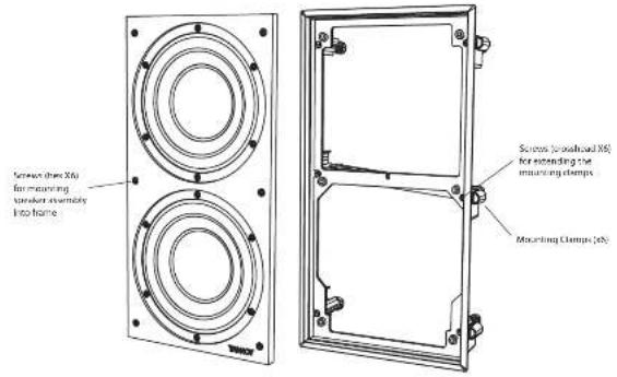
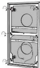
- The subwoofer assembly includes 2 drivers mounted on a rectangular baffle, with the wiring and speaker wire screw terminals. The subwoofer assembly is shipped from the factory already fitted into the mounting frame. To separate the subwoofer assembly from the mounting frame, undo 6 hex screws and remove the subwoofer assembly from the frame (Fig. 8). CAUTION: The subwoofer assembly only fits into the frame in one way. The TAKKGY brand name is at the bottom and the frame is marked "TOP" on the rear.
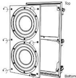
Fig. 8. Undo hex screws to remove Subwoofer Assembly from Frame.
- Use a crosshead screw driver to induce the 5 mounting clamp screws on the mounting frame, to move the mounting clamps into their rest position (Fig. 9). In this position, the mounting clamps are not extended.
- With the damps in their rest position, the frame may now be pressed into the sheetrock aperture/back can (Fig. 10). Orient the frame so that the edge marked TOP on the rear side is at the top. Make sure the speaker wires are not pinched by the frame.
- Tighten the mounting clamp screws clockwise to extend the mounting clamps and secure the frame to the back can sheetwork (Fig. 11). Start at one corner then move to the opposite corner, tightening sufficiently to check for visual orientation, before proceeding to tighten the other two corners. Finish off by tightening the middle clamps. WARNING: Do not over tighten the screws - this is unnecessary to achieve a strong acoustic seal to the back can or wall, and risks damage.
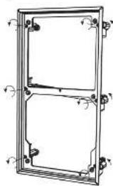
Fig. 9. Undo Mounting Clamp crosshead screws to stow Clamps.
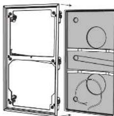
Fig. 10. Press the Frame into the wall aperture.
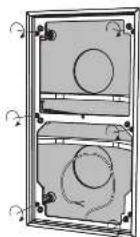
Fig. 11. Tighten Mounting Clamp Screws to extend Clamps.
Wall Clamp Mechanism
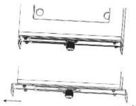
The damping mechanism has been designed to provide an acoustically-optimum bond to the wall surface without risk of distortion to the loudspeaker taffle.
As these screws are tightened, the immensery strong polycarbonate clamping arms will automatically swing round into the locking position, locating the subwoofer frame securely to the inside of the back can or wall surface (Fig. 12).
The design also allows for simple removal of the subwoofer frame.
The clamp mechanism ensures that as the screws are loosened (turned anti-clockwise) the clamp arm travels along its guide before turning itself into the rest position. The captive locking system ensures that the clamp arm cannot drop off the end of the screw to be lost in the back can or wall cavity.
CAUTION: Move all the clamps in the rest position by loosening all screws before attempting to remove the frame assembly from the wall.
Painting
Before proceeding with the installation of the subwoofer assembly into the installed frame, the grille and frame trim edges can be painted to blend with the surrounding decor.
It is strongly recommended that the metal perforated grille is sprayed, as this will avoid clogging of the holes. If painting with a brush is the only option, then several thin coats of paint will provide a superior finish to that achieved by one applied too thickly.
The subcofer is supplied with a paint mask.
-
Press the painting mass into the installed frame. This is left in place while the wall and frame surround is painted (Fig. 13).
-
The painting mask can also be left in place to prevent dust and dirt entering the back can or wall cavity, until the subwoofer assembly is ready to be installed.
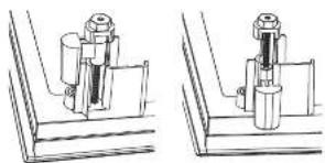
Fig. 12. Mounting Clamps showed position and extended.
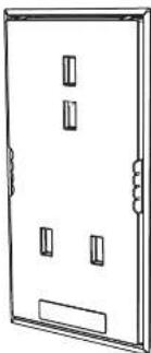
Fig. 13. Paint Mask in place
Subwoofer Installation into the Frame
With the subwoofer frame installed and the wall and frame finished and painted, the subwoofer assembly can now be wired and installed into the frame.
Wiring
WARNING: To avoid potential damage to your loudspeaker, ensure that the amplifier is switched OFF prior to connecting or disconnecting any cables.
WARNING: Before switching the amplifier ON, double check that all connections are secure and that the polarity is correct.
We recommend the use of insulated speaker wiring of between 12 and 18 AWG.
- Remove the paint mask from the frame and pull out the end of the speaker cable. Strip off approximately 8 mm (34") of the outer protective layer from each conductor.
- Hold the subwoofer assembly up close to the installed speaker frame.
- Insert the speaker wires into the correct speaker terminals and secure the connections with a small screwdriver. The positive wire from your amplifier should go to the positive terminal marked (+). The negative wire from your amplifier should connect to the negative terminal marked (-) (Fig.14).
- Make sure that the speaker cable is secured so that it will not move and touch the subwoofer cones in operation.
Subwoofer Installation
- The subwoofer assembly can now be added into the frame, taking care not to trap or pinch the speaker wiring, or your fingers (Fig. 15). The subwoofer assembly only fits into the frame in one way. The Tannoy brand badge is at the bottom and the top of the frame is marked "TOP" on the rear.
- Secure the subwoofer assembly to the frame with the 6 hes screws. To remove the subwoofer, undo these screws and make sure to support the weight of the subwoofer assembly as it comes undone.
Grille Installation
- The grille should be carefully fitted by lining up the edges of the grille with the baffle and frame inside edges (Fig. 16). To avoid indentation damage, do not press the centre of the grille; apply even pressure to each corner as it is pressed firmly into position.
- To remove the grille, loop an opened paper clip or similar length of firm wire, through two holes near a corner and pull gently. The grille is intended to be a tight fit, so insert the wire at each corner in turn, pulling carefully to avoid distortion of the mesh.
System Testing
- Switch on the amplifier with the volume control at its lowest setting. Select a suitable low frequency signal source and slowly turn up the volume to a low level. Check that both subwoofer drivers are working correctly - if not, switch off the amplifier and recheck the connections.
- Carefully check the area surrounding the installation and listen carefully to ensure that there are no buzzes or rattles that could potentially impair enjoyment of the system. If there are, then locate and silence the causes using cable ties, suitable packing material, or extra adhesive in areas.
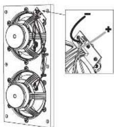
Fig. 14. Wiring the Subwoofer
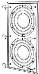
Fig. 15. Installing the Subwoofer Assembly into the frame
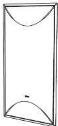
Fig. 16. Installing the Grille into the frame
Guía de instalación
Fig. 3. Installation du fil d'encinte.
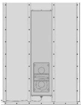
Fig. 4. Vis Sheetrock.
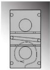
Fig. 4. Parafusos Sheetrock.
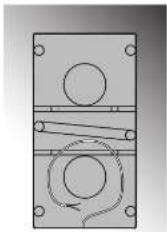
Fig. 5. Sheetrock removido da abertura.
Fig. 7. Sheetrock removido da abertura.
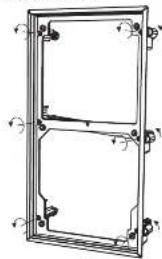
Fig. 14. Cablaggio del subwoofer
Alb. 10. Druk het frame in de muuropening. Alb. 11. Drasi de montageKlemschroeven vast om de klemmen te verlengen.
Muurklemmechanisme
Fig. 1 Installera den bakre burken mellan pinnbulten
| Performance | |
| Frequency response (1.3 dB) 100 Hz - 2 kHz | |
| Frequency response (-10 dB) 45 Hz - 2.5 kHz | |
| Sensitivity (W ± 10) 90 dB | |
| Power handling (DCI) | |
| Average 700 V | |
| Programme 420 V | |
| Peak 800 V | |
| Recommended amplifier power (2.0 V) x 0.0 | |
| Nominal Impesance (Lo Z) 3.0 | |
| Rated maximum SPL (1 m, Lo Z) 116 dB | |
| Average 113 dB | |
| Peak | 119 dB |
| Crossover point | NA |
| Transducers | |
| Low frequency diameter/material/type | 7 x 219 mm (R2) |
| Physical | |
| Back Can | BACK CAN PCI SUB IM/ Wood |
| Baffle | Reflex loaded UCH V-0 rated ABS |
| Grille | Steel, with weather-resistant coating |
| Clamping design | Security toggle clamp |
| Connectors | Phoenix Contact terminal block |
| Dimensions (W x W x D) | 1465 x 345 x 113 mm (52.7 x 13.6 x 4.5") |
| Bezel dimensions | 495.6 x 264.5 mm (19.5 x 10.4") |
| Mounting depth | 93.1 mm (3.7") |
| Hole cutout dimensions | (82.5 x 252.5 mm (19.5 x 5.4") |
| Net weight | 16.9 kg (37.2 lb) |
| Packed quantity | 1 |
| Included accessories | PCI SUB IM/ Slide, paint mask, cutout template .BACK CAN: PCI SUB IM/ washers (x1.2), screws (x1.2), bracket (x4), cable clamp. |
| Optional accessories | PCI SUB IM/ and Back Can: PCI SUB IM are also available separately |
Other important information

Important information
- Register online. Please register your new Music Tribe equipment right after you purchase it by visiting musctribe.com. Registering your purchase using our simple online form helps us to process your repair claims more quickly and efficiently. Also, read the terms and conditions of our warranty, if applicable.
- Malfunction. Should your Music Tribe Author and Reseller not be located in your vicinity, you may contact the Music Tribe Authorized Fulfill for your country listed under "Support" at musicitibe.com. Should your country not be listed, please check if your problem can be dealt with by our "Online Support" which may also be found under "Support" at musicitibe.com. Alternatively, please submit an online warranty claim at musicitibe.com BEFORE returning the product.
- Power Connections. Before plugging the unit into a power socket, please make sure you are using the correct mains voltage for your particular model. Equity lines must be replaced with fuses of the same type and rating without exception.

Responsible Party Name: Music Tribe Commercial NV Inc.
Address: 5270 Procyon Street,
Las Vegas NV 89118,
United States
Phone Number: +1 702 800 8290
PCI SUB IW
This equipment has been tested and found to comply with the limits for a Class B digital device, pursuant to part 15 of the FCC Rules. These limits are designed to provide reasonable protection against harmful interference in a residential installation. This equipment generates, uses and can radiate radio frequency energy and, if not installed and used in accordance with the instructions, may cause harmful interference to radio communications. However, there is no guarantee that interference will not occur in a particular installation. If this equipment does cause harmful interference to radio or television reception, which can be determined by turning the equipment off and on, the user is encouraged to try to correct the interference by one or more of the following measures:
• Reorient or relocate the receiving antenna.
- Increase the separation between the equipment and receiver.
- Connect the equipment into an outlet on a circuit different from that to which the receiver is connected.
- Consult the dealer or an experienced radio/TV technician for help.
This device complies with Part 15 of the FCC rules. Operation is subject to the following two conditions:
(1) this device may not cause harmful interference, and (2) this device must accept any interference received, including interference that may cause undesired operation.
Important information:
Changes or modifications to the equipment not expressly approved by Music Tribe can void the user's authority to use the equipment.
CE
Hereby, Music Tribe declares that this product is in compliance with Directive 2014/35/EU, Directive 2014/30/EU, Directive 2011/65/EU and Amendment 2015/863/EU, Directive 2012/19/EU, Regulation 519/2012 REACH SVHC and Directive 1907/2006/LC.
Full text of EU DoC is available at https://community.musictribe.com/
EU Representative: Music Tribe Brands DK A/S Address: Ib Spang Olsens Gade 17, DK - 8200 Aarhus N, Denmark
UK Representative: Music Tribe Brands UK Ltd St George's House 215-219 Chester Road, Manchester, Greater Manchester, England, M15 4UE



- PCI IN-WALL SUBWOOFER
- PCI SUB IW
- BACK CAN PCI SUB IW
- LEGAL DISCLAIMER
- LIMITED WARRANTY
- BESCHRÄNKTE GARANTIE
- UNPACKING
- SAFETY NOTICES
- INTRODUCCIÓN
- PRODUCT FEATURE IDENTIFICATION PRODUCT FEATURE IDENTIFICATION
- INSTALLATION GUIDE
- BACK CAN INSTALLATION
- PROCEDURE
- ALTERNATIVE INSTALLATION WITHOUT THE BACK CAN
- SUBWOOFER FRAME INSTALLATION
- WALL CLAMP MECHANISM
- PAINTING
- SUBWOOFER INSTALLATION INTO THE FRAME
- WIRING
- SUBWOOFER INSTALLATION
- GRILLE INSTALLATION
- SYSTEM TESTING
- GUÍA DE INSTALACIÓN
- MUURKLEMMECHANISME
- OTHER IMPORTANT INFORMATION
- IMPORTANT INFORMATION
- CE
Brand : TANNOY
Model : PCI SUB IW WITH BACK CAN
Category : Loudspeaker