
iW 4DC - Speaker TANNOY - Free user manual and instructions
Find the device manual for free iW 4DC TANNOY in PDF.

| Product type | Dual concentric 2-way in-wall speaker |
| Brand | Tannoy |
| Model | iW 4DC |
| Main features | Dual Concentric technology, polycarbonate dogging mechanism, paintable perforated metal grille, wall mounting with template |
| Care and cleaning | Clean with a dry cloth only |
| Safety | Do not install near heat sources or water, use specified accessories, do not block openings |
| Spare parts and repairability | Spare parts available through Tannoy distribution network; register the product on music-tribe.com to facilitate repairs |
| General information | Designed for installation in standard stud walls; requires a sealed back volume for optimal performance |
Frequently Asked Questions - iW 4DC TANNOY
User questions about iW 4DC TANNOY
0 question about this device. Answer the ones you know or ask your own.
Ask a new question about this device
Download the instructions for your Speaker in PDF format for free! Find your manual iW 4DC - TANNOY and take your electronic device back in hand. On this page are published all the documents necessary for the use of your device. iW 4DC by TANNOY.
USER MANUAL iW 4DC TANNOY
natural_image
Simple line drawing of a rectangular device with a small attached element (no text or symbols)
natural_image
Simple line drawing of a rectangular container with a small protrusion on top (no text or symbols)
natural_image
Simple line drawing of a rectangular device with a small protrusion on top (no text or symbols)
natural_image
Simple line drawing of a rectangular frame with rounded corners and a central gray rectangle (no text or symbols)iW Series
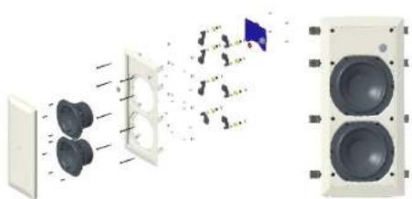
iW 62S-WH
2 x 6" In-Wall Subwoofer (White)
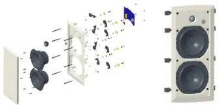
iW 62DS-WH
3 Way 6" In-Wall Loudspeaker (White)
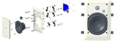
iW 6DS-WH
2 Way 6" In-Wall Loudspeaker (White)
iW 4DC-WH
2 Way 4" Dual Concentric In-Wall Loudspeaker (White)
EN
ES
FR
DE
PT
IT
NL
SE
PL
JP
CN
2 MW Series Quick Start Guide 3
EN
Safety Instruction
-
Please read and follow all instructions.
-
Keep the apparatus away from water, except for outdoor products.
-
Clear only with a dry cloth.
-
Do not block any ventilation openings. Install in
incumance with the manufacturer's instructions
-
Do not install near any heat sources such as radi heat registers, stones or other apparatus (including amortizers) that produce heat.
-
Use only attachments/accessories specified by the manufacturer.
ES

- Use only specified
carts, stands, tripods
brackets, or tables. Use
When we have the cari
which finding the care apparatus combination
DE
-
00
-
liquid installing in confined spaces like bicicaver
-
Do not place near naked flame sources, such as lighted candles.
-
Operating temperature range 5° to 45°C (41° to 113°F).
PT
[Non-Text]
LEGAL DISCLAIMER
Music Tribe accepts no liability for any loss which may be suffered by any person who relies either wholly or in part upon any description, photograph, or statement contained herein. Technical specifications, appearances and other information are subject to change without notice. All trademarks are the property of their respective owners. Milan, Mark Teknik, Lab Gruppen, Lake, Tammy, Turboamid, TC Electronic, TC Helicon, Behringen, Buyers, Astro Microphones and Coolactio are trademarks or registered trademarks of Music Tribe Global Brands Ltd. © Music Tribe Global Brands Ltd. 2024 All rights reserved.
LIMITED WARRANTY
For the applicable warranty terms and conditions and additional information regarding Music Tribe's Limited Warranty, please see complete details online at community.muistribe.com/support.
BESCHRÄNKTE GARANTIE
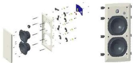
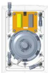
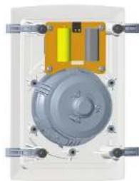
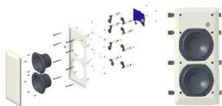
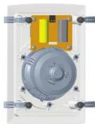
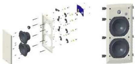
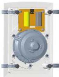
Thank you for purchasing this Tanny in-wall Monitor System product. Tanny in-wall speaker systems are monitor-quality speaker systems based on the company's expertise in the manufacture of premium quality cabinet loudspeakers and studio monitors. Exclusive drive unit designs and wide bandwidth technology ensure that these in wall loudspeakers deliver the performance that is essential for applications such as multi-room distributed audio installations, home theatre systems and discrete audio systems, as well as in the many other applications where space is at a premium but ultimate sound quality is still paramount. The speaker construction is based around a rigid mounted ABS battle with excellent structural integrity; this, when combined with the secure polycarbonate clamp mounting system (patient applied for 03158929), ensures a performance-enhancing rigid acoustic coupling with the wall surface, and an immensely stable platform for the drivers to deliver optimum performance. Complementing any style of decor, the perforated metal grille and low profile mounting frame can be painted to blend in seamlessly with the domestic environment. The result is a system offering audible quality sound with minimal invasion of the living space.
Unpacking
Every Tannoy product is carefully inspected before shipment. After unpacking, please inspect your product to ensure no damage has occurred in transit. In the unlikely event of damage, please notify your dealer and retain all shipping materials as your dealer may require return shipment.
Safety Notices
Tannoy will not be held responsible for any damages caused by the improper installation of these loudspeakers.
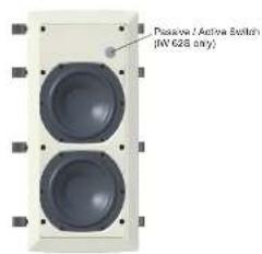
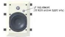
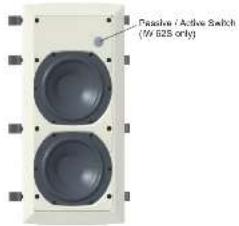
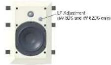
Product Feature Identification
Common Features on all models
iW 6DS and iW 62DS LF Adjustment Switch
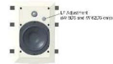
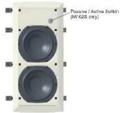
iW 62S Passive/Active Switch
8 W Series Quick Start Guide 9
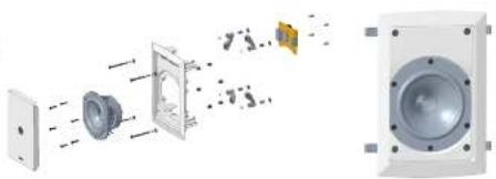
Product Feature Identification
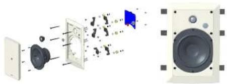
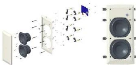
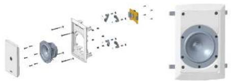
iW 4DC-WH
2 Way 4" Dual Concentric In-Wall Loudspeaker (White)
natural_image
Diagram of a speaker assembly showing components from an open source to a speaker, with no visible text or symbols.iW 6DS-WH
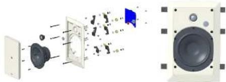
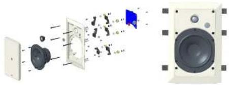
2 Way 6' In-Wall Loudspeaker (White)
natural_image
Exploded view diagram of a speaker assembly showing sound waves, microphone, and speaker components (no text or labels)iW 62DS-WH
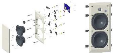
3 Way 6' In Wall Loudspeaker (White)
natural_image
Diagram of a speaker system with two speakers and an output unit, showing sound wave propagation (no text or labels)iW 625-WH
2 x 6' In-Wall Subwoofer (White)

natural_image
Diagram of a speaker system with two speakers and an output tower, showing sound waves and components (no text or labels)iW62 Backcan
Optional pre-install backcan for IW 62DS-VH and IW 62S-VH models. The backcan comes with its own installation instructions.
Accessories
Installation Templates (supplied)


Wiring and Setting Up
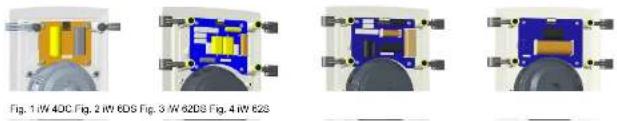
Terminal Panel Connections and Driver Earthing
-
WARNING: To avoid potential damage to your loudspeaker, ensure that the amplifier is switched OFF prior to connecting or disconnecting any cables.
-
Before switching the amplifier ON, double check that all connections are secure and that the polarity is correct.
Connection in Single Wire Mode
The screw terminals are designed to take loudspeaker cable of AWG24 to AWG12 in size.
-
Strip off approximately 8 mm (34") of the outer protective layer and twist the inner cores together. Insert the core and use a small flat screwdriver to secure, ensuring that correct polarity is maintained see Figs 1 to 3.
-
On the IW SZDS, optimum performance in single wire mode will be achieved if loudspeaker cable connections from the amplifier are made to the high frequency [HF] terminals of the loudspeaker see Fig 3.
Connection in Bi-Wire Mode - iW 62DS
- Two sets of cabling are required for each speaker: one for the LF (low frequency), connection and one for the HF (high frequency) connection.
- Please note in bi-wire mode that the link wires must be cut.
- If your amplifier is not equipped with separate output terminals for bass and treble information then, at the amplifier end of the cables, twist the LF + (positive) and the HF + (positive) together.
- Connect these to the amplifier channel positive terminal marked + (plus) or coloured red.
- Twist the LF (negative) and the IIF (negative) cables together and connect them to the amplifier channel negative terminal marked - (minus) or coloured black.
- At the loudspeaker end, connect the LF and LF cables to the loudspeaker LF terminals, ensuring that you note the polarity markings on the cable sheathing.
- Then proceed to connect the HF + and HF- to the HF terminals on the same loudspeaker: see Fig 3.
Connection of Earth or Ground Lead - iW 6DS and iW 62DS
- The RV 60S and RV 620S models have an extra terminal designed to optimise performance further by taking advantage of the driver earthing facility. Use a shielded or screened loudspeaker cable; connecting the screening termination to the earth or ground (green) terminal on the loudspeaker and to the ground or earth connection on the amplifier.
- Alternatively if you are not using a screened loudspeaker cable but wish to utilise the earthing facility, run a single cable between the earth or ground [green] terminal on the loudspeaker to the earth [ground] connection on the amplifier.
- Switch the amplifier on with the volume control set at its lowest setting. Select a favourite source and slowly turn up the volume to a low level. Check that bass and treble information is being reproduced from the speaker. If not, switch off the amplifier and recheck the connections.
Bi-Amping iW 62DS
- Bi-amping extends the principle of bi-wiring one stage further. In this connection option, separate power amplifiers are used for bass and treble signals in each loudspeaker.
- Ensure that the link cables have been cut and that correct polarity is maintained throughout.
- If two stereo amplifiers are used, it is recommended that one supplies bass information to the loudspeakers and the other, the treble information - see Fig 3.
Connecting the iW 62S
- The iW 625 may be operated in either passive or active mode.
- In passive mode, the internal low pass filters provide the transition to the main speakers.
- In active mode the internal low pass filters are bypassed, to allow the use of an external controller and power amplifier. This mode of operation is preferred for optimum performance, as it allows low frequency extension and equalization to be applied, and the low pass crossover to be optimally configured to the main speaker setup and room characteristics.
- Passive or active operation can be set by the front baffle switch, behind the grille.
- Run cabling from one pair of speaker terminals, back to the amplifier, ensuring the correct polarity. The other set of terminals are a link that can be run to another speaker.
Quick Star Guide
Installation Guide
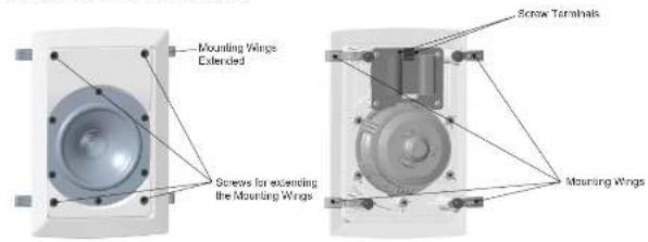
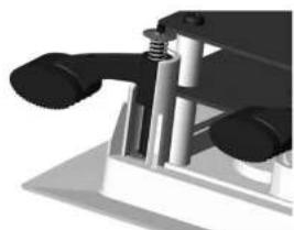
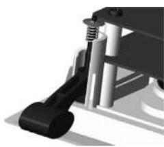
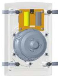
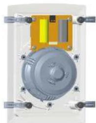
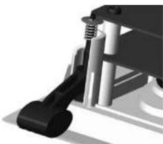
Wall Clamp Mechanism
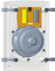
A unique damping mechanism has been designed to provide an acoustically optimum bond to the wall surface without risk of distortion to the loudspeaker frattle.
The IW 4DC has four mounting clamps and screws, the IW 6DS has six, and the IW 62DS and IW 62S have eight. As these screws are tightened, the immensely strong polycarbonate clamping arms will automatically swing round into the locking position, locating securely to the inside of the wall surface.
The design also allows for simple removal or reorientation of the loudspeaker.
The spring-loaded clamp mechanism ensures that as the screws loosened (turned anti-clockwise), the clamp arm travels along its guide before turning itself into the rest position. The captive locking system ensures that the clamp arm cannot drop off the end of the screw to be lost in the wall cavity.
IMPORTANT
Get all the clamps in the rest position by loosening all screws before attempting to remove the speaker from the wall.
Installation
WARNING: If adding new speakers to an existing installation, or simply replacing old ones, you must ensure that the amplifier driving the system is switched OFF.
WARNING: Price to proceeding with the installation, ensure that you accurately determine the position of electrical cabling, pipe work and wall studs. Having selected a wall location clear of any obstruction, measure carefully to ensure the correct placement.
Painting
Before proceeding with the installation, the grille and baffle panel can be painted to blend with the surrounding decor.
When painting the barrel, be sure to carefully mask off the driver assemblies. It is important to ensure that paint does not come into contact with the cone, roll surround or HF unit. It is strongly recommended that the metal perforated grille is sprayed as this will avoid clogging of the holes. If painting with a brush is the only option, then several thin coats of paint will provide a superior finish to that achieved by one applied too thickly.
The speaker is supplied with a sheet of acoustically transparent protective foam fixed to the inside of the grille. Having painted the grille to match the room decor please remove the original foam and replace with the spare sheet supplied in the accessory pack. It is important that this replacement foam is bonded to the grille over it's entire area, using a suitable spray adhesive. Failure to do so will result in audible resonance.
Overview
Tannoy in-wall loudspeakers have been designed for installation into standard stud partition wall systems constructed with 102 by 51 mm (4" by 2") timber at 406 mm (16") centres, however, it is envisaged that they will generally be used in cavity wall installations constructed with standard thickness plasterboard. These are guidelines and therefore do not preclude use of the Tannoy in-wall products in different locations and a wide range of other wall construction types, as long as they have a secure clamping surface up to maximum thickness of 25.4 mm (1").
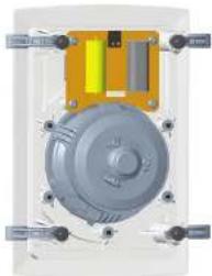
Driver cone movement at low frequencies may become excessive unless steps are taken in the wall cavity void behind the loudspeaker to provide a well sealed and accurately controlled near 'enclosure' volume. This will effectively act as an enclosure behind the speaker (see Speaker Loading Volume section in this manual), failure to ensure this, will affect the loss and midrange performance unfavourably.
natural_image
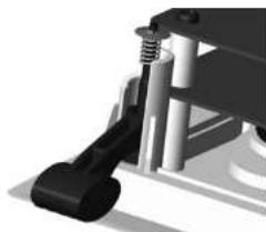
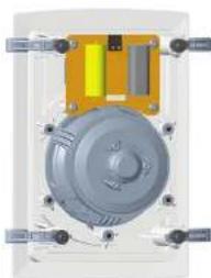
Close-up of a mechanical assembly with cylindrical components and mounting base (no visible text or symbols)Fig. 5 Clamps in the pre-install position (rest)

natural_image
Mechanical assembly diagram showing a lever and shaft assembly (no text or symbols)Fig. 6 Clamps in the install position
12 IV Series Quick Start Guide 13
Positioning
There is a great deal of mounting location flexibility with these models when used in home cinema or multi channel systems. In particular, please note that due to the unique point source symmetrical dispersion properties of the Tannoy Dual Concentric drive unit, the model (W/DC and W-6DS can be mounted in either portrait (in stud partition wall situations) or landscape positions, where sufficient space exists behind the wall surface.
To achieve the optimum spectral and stereo performance select your mounting location as follows:
Vertical plane
Align the front baffle centres at the intended listening height, usually dictated by the normal seated listening position. For audio use, when positioned in front of the listener, this will usually be in the height range of 1700 mm to 1700 mm (43° to 67°). For use as home cinema rear effects speakers mounted on the rear walls of the mom, the mounting height range is 1530 mm to 2140 mm (60° to 84°).
Horizontal plane
The loudspeakers should be located between 1500 mm to 4500 mm (60" to 180") apart. The room size and shape will dictate the final mounting location, but generally the listening position, when used as a stereo pair, should be set slightly further away than the speakers are apart.
When used as rear effects speakers in a home cinema system, the ideal viewing point will establish the distance from the rear wall to the listening position. Avoid positioning the loudspeakers in corners of the room, as this will have a negative effect on performance; maintain a distance of 1 m (39°) away from a corner.
Speaker Fitting
Remember .... Measure twice - cut once!
-
Once the mounting location has been selected, use the template provided to mark out the area of wall material to be cut out. Carefully remove the waste, checking again that there are no interferences from studs/wire/pipes etc.
-
Install the loudspeaker ceiling ensuring that the wiring route is laid clear of all screws and nails that could potentially damage the cable insulation. Allow sufficient cable length at the speaker end to allow for an unrestricted connection.
-
It is necessary to block off the void behind the speaker by suitable means (insulation material or foam) to create an "enclosure" area. This will offer the speaker the required loading volume as detailed in the specification section of this manual.
-
It is important to provide some acoustic damping between the speaker and the near wall surface. We recommend use of a BAF sheet (Bonded Acrylic Fibre). Ensure that all materials used comply with local fire and building regulations.
-
Strip B mm (16 inch) of shielding from the end of the speaker cables in preparation for connection to the terminals on the rear of speaker.
-
Check that the clamping arms are aligned as shown prior to insertion in the wall.
-
Connect the speaker cable observing the correct wiring polarity. The positive terminal (marked + and coloured red) should receive the positive cable (usually marked with a repeated stamped name, line or raised rib) and the negative terminal (marked - and coloured black) the negative cable.
-
Insert the baffle into the pre-prepared hole in the wall, ensuring that the speaker wire is located securely away from the driver, as contact with the driver cone will cause annoying buzzes.
-
Each of the clamp screws can now be tightened (clockwise). Starting at one corner then move to the opposite corner, tightening sufficiently to check for visual orientation, before proceeding to tighten the other two corners.
-
Finish off by tightening the middle clamps.
WARNING: Do not over tighten the screws - this is unnecessary to achieve a strong acoustic seal to the wall, and risks damaging the wall surface
-
Repeat the installation procedure for the other loudspeakers and complete the connection process to the amplifier.
-
Once again ensure that correct cable polarity is observed.
-
Switch on the amplifier with the volume control at its lowest setting. Select a signal source and slowly turn up the volume to a low level. Check that bass and treble information comes from both speakers - if not, switch off the amplifier and recheck the connections.
-
Carefully check the area surrounding the installation and ensure that there are no buzzes or rattles that could potentially impair enjoyment of the system. If there are, then locate and silence the causes using cable ties or suitable packing material.
-
Optimum performance will be assisted by the use of silicone sealant to seal gaps between the studs and the wallboard material. This cavity sealing will help to create a near airlight seal. Do not silicone the taffle to the wall as the clamping mechanism creates an effective bond.
natural_image
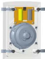
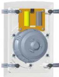
Technical diagram of a mechanical assembly with central disc and surrounding components (no visible text or labels)Fig. 7 Changes in the pre-install position (W-ADC shown)
natural_image
Cross-sectional diagram of a mechanical or electrical component with no visible text or symbolsFig. 8 Clamps in the install position (W4DC)
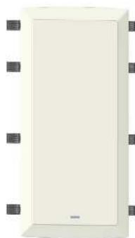
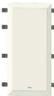
Grille Fitting and Removal
The grille should be carefully fitted to the front grille aperture, by lining up the edges of the grille carefully with the grille. To avoid indentation damage, do not press the centre of the grille; apply even pressure to the corner as it is pressed firmly into position.
To remove the grille, loop an opened paper clip or similar length of firm wire, through two holes near a corner and pull gently. The grille is intended to be a light fit, so insert the wire at each corner in turn, pulling carefully to avoid distortion of the mesh.
Speaker Loading Volume
There are two simple approaches to achieve a sealed 'enclosure' to provide the correct driver loading area behind the speaker.
The chosen method will depend on whether the wall is under construction, as in a new building project, or an existing wall where access is limited.
Option 1
Stud partition walls under construction, with 102 mm by 51 mm (4 by 2 inch) timber at 406 mm (16 inch) centres.
- Block off the cavity, above and below the intended speaker opening, with the same framing timber. The distance between these two internal barriers should be as shown in this table:
| Model Distance |
| Iw4 DC 410 mm (16") |
| Iw 6DS 550 mm (21.5") |
| Iw 62DS 825 mm (32.5") |
| Iw 62S 825 mm (32.5") |
Inside of stud partition viewed from rear
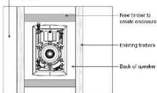
Fig 10. Stud partition under construction - 15" limber centers
natural_image
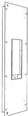
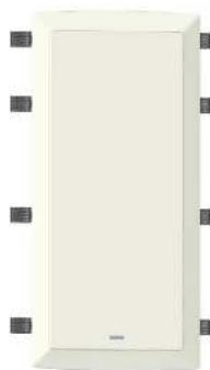
Exterior view of a white rectangular appliance with black square buttons at corners (no text or symbols visible)Fig. 8 IW 62DS and IW 62S Grille Detail
Inside of stud partition viewed from rear
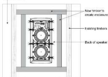
Fig 11. Stud partition under construction - limber centers over 16"
Speaker Loading Volume (continued)
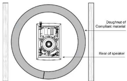
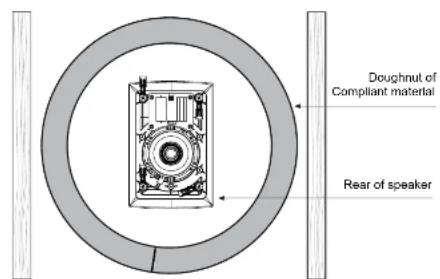
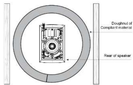
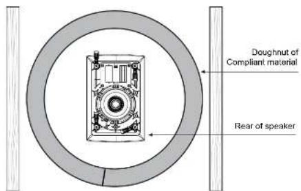
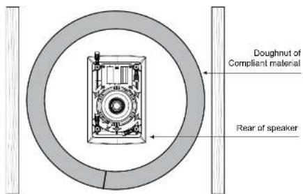
Option 2
Existing timber stud partition, or any other wall type constructed with a 102 mm (4 inch) cavity depth.
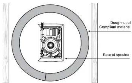
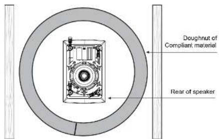
- Many professional installers use a "doughnut" of compliant material, which can be inserted as a tight fit between the two surfaces of the partition or into the wall cavity. The length of the internal surface of the strip of material determines the 'enclosure' volume. For each model, cut the strips into lengths listed in the table below, insert into the cavity, and join to form a ring that will ensure the correct volume - see Fig. 12
| Model Length |
| IW 1DC 1380 mm (54") |
| IW 6DS 1570 mm (62") |
| IW 62DS 1920 mm (75 12 ") |
| IW 62S 1920 mm (75 12 ") |
Inside wall, viewed from rear
Rear of stud Rear of stud
Fig 12: Stud partition or wall cavity, using compliant material of appropriate thickness to create a light seal
Introducción
Interruptor de ajuste LF de iW 6DS y iW 62DS
Interruptor pasivo/activo iW 62S
Quick Star Guide
17
natural_image
Diagram showing a speaker assembly with components and sound waves, no text or symbols presentiW 6DS-WH
natural_image
Exploded view diagram of a speaker assembly showing sound waves, speaker chamber, and speaker base (no text or labels)iW 62DS-WH
natural_image
Exploded view diagram of a multi-tiered speaker system with speaker modules and sound output (no text or labels)iW 62S-WH
2 subwoofers de pared de 6" (blanco)
natural_image
Diagram showing sound wave propagation through a speaker system with two speakers and a blue flag marker (no text or symbols)18 TV Series
Quick Star Guide
19
Caja trasera iW62
natural_image
Close-up of a mechanical assembly with cylindrical components and mounting base (no visible text or symbols)Fig. 5 Clamps in the pre-install position (rest)

natural_image
Mechanical assembly diagram showing a lever and shaft assembly (no text or symbols visible)Fig. 6 Clamps in the install position
Posicionamiento
natural_image
Technical diagram of a mechanical assembly with no visible text or symbolsFig. 7 Camps in the pre-meal position (W 4DC show)
natural_image
Mechanical assembly diagram showing a rotating component with mounting flanges and a central hub (no text or symbols visible)Fig. 8 Clamps in the install position (W 4DC)
22 IV Series Quick Start Guide 23
natural_image
Exterior view of a white rectangular appliance with black buttons at corners (no text or symbols visible)Fig. 9 IW 62DS and IW 62S Grile Detail
Inside of stud partition viewed from rear
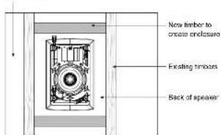
Fig 10: Stud partition under construction - 16 timber centers
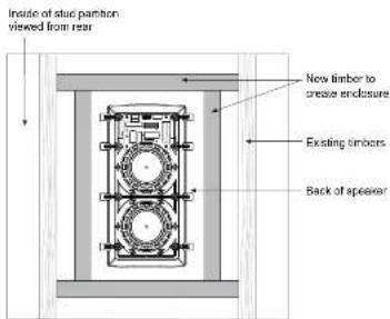
Fig 11: Stud partition under construction – timbar centers over 15"
Rear of stud Rear of stud
Fig 12: Stud partition or wall cavity, using compliant material of appropriate thickness to create a light seal
24 PG Series Quick Start Guide- 25
Introduction
26 PG Series Quick Start Guide-27
natural_image
Diagram showing a speaker assembly with lens, frame, and components (no text or labels)iW 6DS-WH
natural_image
Exploded view diagram of a speaker assembly showing sound waves, speaker chamber, and speaker base (no text or labels)iW 62DS-WH
natural_image
Diagram of a multi-tiered speaker system with visible sound waves and components (no text or labels)iW 62S-WH
natural_image
Diagram showing sound wave propagation from speaker to speaker array (no text or symbols)iW62 Backcan
natural_image
Close-up of a mechanical assembly with cylindrical components and mounting base (no visible text or symbols)Fig. 5 Clamps in the pre-install position (rest)

natural_image
Mechanical assembly diagram showing a lever and bracket (no text or symbols)Fig. 6 Clamps in the install position
Positionnement
natural_image
Technical diagram of a mechanical assembly with no visible text or symbolsFig. 7 Clamps in the pre-install position (IN ADC shown)
natural_image
3D rendering of a mechanical component with concentric rings and mounting holes (no visible text or symbols)Fig. 8 Clamps in the install position (W 4DC)
natural_image
Exterior view of a white rectangular appliance with black mounting brackets (no text or symbols visible)Fig. 8 IW 62DS and IW 62S Grille Detail
Inside of stud partition viewed from rear
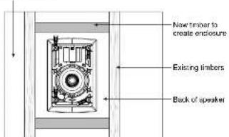
Fig 10: Stud partition under construction - 16* timber centers
Inside of stud partition viewed from rear

Fig 11: Stud partition under construction – limber centers over 16°
Inside wall, viewed from rear
Rear of stud Rear of stud
Fig 12: Slud partition or wall cavity, using compliant material of appropriate thickness to create a tight seal
Einführung
Quick Star Guide
natural_image
Exploded view diagram of a speaker assembly showing internal components and sound waves (no text or labels)iW 6DS-WH
natural_image
Exploded view diagram of a speaker assembly showing sound waves, speaker blades, and speaker base (no text or labels)iW 62DS-WH
natural_image
Exploded view diagram of a speaker system showing front, side, and back views with no visible text or labelsiW 62S-WH
natural_image
Diagram showing sound wave propagation through a speaker array with two speakers and a blue flag marker (no text or symbols)iW62 Rückwand
Installationshandbuch
Wandklemmmechanismus
natural_image
Close-up of a mechanical assembly with cylindrical components and mounting base (no visible text or symbols)Fig. 5 Clamps in the pre-install position (rest)
natural_image
Mechanical assembly diagram showing a lever and shaft assembly (no text or symbols visible)Fig. 6 Clamps in the install position
Positionierung
natural_image
Technical diagram of a mechanical assembly with central disc and surrounding components (no visible text or labels)Fig. 7 Camps in the pre-install position (W 4DC shown)

natural_image
3D mechanical assembly diagram showing a central rotating component with surrounding components (no text or symbols visible)Fig. 9 Clamps in the install position (M 4DC)
natural_image
Exterior view of a white rectangular wall-mounted device with black square buttons at corners (no text or symbols visible)Fig. 9 IW 62DS and IW 62S Grile Detail
Inside of stud partition viewed from rear
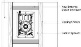
Fig 10: Stud partition under construction - 16" timber centers
Inside of stud partition viewed from rear
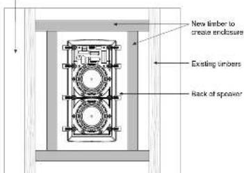
Fig 11: Stud partition under construction – timber centers over 16°
Inside wall, viewed from rear
Rear of stud Rear of stud
Fig 12: Stud partition or wall cavity, using compliant material of appropriate thickness to create a tight seal
Introdução
Chave de ajuste iW 6DS e iW 62DS LF
Interruptor passivo/ativo iW 625
natural_image
Exploded view diagram of a speaker assembly showing internal components and sound wave propagation (no text or labels)iW 6DS-WH
Alto falante de parede de 2 vias e 6° [franco]
natural_image
Exploded view diagram of a speaker assembly showing sound waves, speaker chamber, and speaker base (no text or labels)iW 62DS-WH
natural_image
Diagram of a multi-tiered speaker system with visible sound waves and components (no text or labels)iW 62S-WH
Subwoofer de parade 2 x 6" (branco)
natural_image
Diagram showing sound wave propagation from speaker to speaker array (no text or symbols)Backcan iW62
natural_image
Close-up of a mechanical assembly with cylindrical components and mounting base (no visible text or symbols)Fig. 5 Clamps in the pre-install position (rest)
natural_image
Mechanical assembly diagram showing a lever and pivot (no text or symbols)Fig. 6 Clamps in the install position
Posicionamento
natural_image
Technical diagram of a mechanical assembly with central rotating component and surrounding components (no visible text or labels)Fig. 7 Clamps in the pre-install position (IN 4DC shown)
natural_image
Mechanical assembly diagram showing a central rotating component with surrounding components (no text or symbols visible)Fig. 8 Clamps in the install position (W4DC)
Inside of stud partition viewed from rear

Fig 10: Stud partition under construction - 16* timber centers
natural_image
Exterior view of a beige rectangular wall-mounted device with black square connectors at the top (no text or symbols visible)Fig. 8 IW 62DS and IW 62S Grille Detail
Inside of stud partition viewed from rear

Fig 11: Stud partition under construction – limber centers over 16°
Inside wall, viewed from rear
Rear of stud Rear of stud
Fig 12: Stud partition or wall cavity, using compliant material of appropriate thickness to create a light seal
Introduzione
Quick Star Guide
53
natural_image
Exploded view diagram of a speaker assembly showing internal components and sound waves (no text or labels)Modello iW 6DS-WH
natural_image
Exploded view diagram of a speaker into an open chamber with sound waves and components (no text or labels)iW 62DS-WH
natural_image
Diagram of a multi-tiered speaker system with visible sound waves and components (no text or labels)iW 62S-WH
Subwoofer a parete 2 x 6" (bianco)
natural_image
Diagram showing sound wave propagation from a speaker into a multi-noise system, with no visible text or symbols.iW62 Backcan
natural_image
Close-up of a mechanical assembly with cylindrical components and mounting base (no visible text or symbols)Fig. 5 Clamps in the pre-install position (rest)

natural_image
Mechanical assembly diagram showing a lever and shaft assembly (no text or symbols visible)Fig. 6 Clamps in the install position
natural_image
Technical diagram of a mechanical assembly with central circular component and surrounding components (no visible text or labels)Fig. 7 Camps in the pre-most position (pW ≤ DC shown)
natural_image
3D mechanical assembly diagram showing a central rotating component with surrounding components (no text or symbols visible)Fig. 8 Clamps in the install position (W 4DC)
natural_image
Exterior view of a white rectangular appliance with black mounting brackets (no text or symbols visible)Fig. 9 IW 62DS and IW 62S Grile Detail
Inside of stud partition viewed from rear
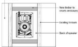
Fig 10: Stud partition under construction - 16' timber centers
Inside of stud partition viewed from rear
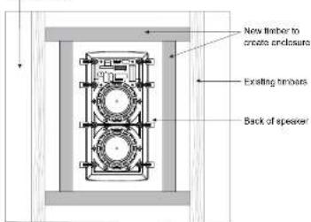
Fig 11. Stud partition under construction - timber centers over 16°
Inside wall, viewed from rear
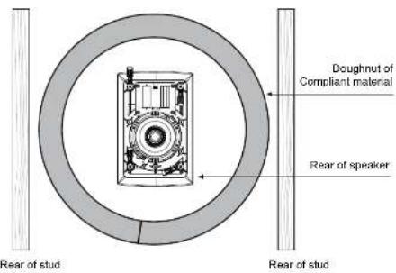
Fig 12: Stud partition or wall cavity, using compliant material of appropriate thickness to create a light seal
Invoering
iW 6DS en iW 62DS LF-instelschakelaar

natural_image
Exploded view diagram of a speaker assembly showing internal components and sound wave propagation (no text or labels)iW 6DS-WH
natural_image
Exploded view diagram of a speaker assembly showing sound waves, speaker chamber, and speaker base (no text or labels)iW 62DS-WH
3-weg 6" wandinbouwfuldspreker (wit)
natural_image
Exploded view diagram of a multi-tiered speaker system with visible sound waves and components (no text or labels)iW 62S-WH
natural_image
Diagram showing sound wave propagation from speaker to speaker array (no text or symbols)iW62 Backcan
natural_image
Close-up of a mechanical assembly with cylindrical components and mounting base (no visible text or symbols)Fig. 5 Clamps in the pre-install position (rest)

natural_image
Mechanical assembly diagram showing a lever and shaft assembly (no text or symbols visible)Fig. 6 Clamps in the install position
Positionering
natural_image
Technical diagram of a mechanical assembly with no visible text or symbolsFig. 7 Clamps in the pre-install position (in 4DC shown)
natural_image
Cross-sectional diagram of a mechanical device showing internal components and mounting points (no text or symbols)Fig. 6 Clamps in the install position (W 4DC)
natural_image
Exterior view of a white rectangular appliance with black square buttons on both sides (no text or symbols visible)Fig. 8 IW 62DS and IW 62S Grille Detail
Inside of stud partition viewed from rear
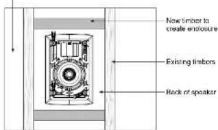
Fig 10: Stud partition under construction - 16" timber centers
Inside of stud partition viewed from rear
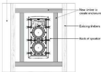
Fig 11: Stud partition under construction - timber centers over 16°
Inside wall, viewed from rear
Rear of stud Rear of stud
Fig 12: Stud partition or wall cavity, using compliant material of appropriate thickness to create a light seal
Introduktion
Quick Star Guide
natural_image
Diagram of a speaker assembly showing components and light path (no text or labels)iW 6DS-WH
2 Way 6" In-Wall Högtalare (vt)
natural_image
Diagram showing sound wave propagation from speaker to speaker, with no visible text or symbolsiW 62DS-WH
3. xigs 6' inbygd högtalare (vit)
natural_image
Diagram of a speaker system with sound waves and speaker units, showing light path from speaker to speaker (no text or labels)iW 625-WH
2 x 6" In-Wall Subwoofer (wt)

natural_image
Diagram showing sound wave propagation from a speaker into a multi-noise chamber, with no visible text or symbols.iW62 Backcan
natural_image
Close-up of a mechanical assembly with cylindrical components and mounting base (no visible text or symbols)Fig. 5 Clamps in the pre-install position (rest)

natural_image
Mechanical assembly diagram showing a lever and shaft assembly (no text or symbols)Fig. 6 Clamps in the install position
Positionering
natural_image
Technical diagram of a mechanical assembly with central disc and surrounding components (no visible text or labels)Fig. 7 Camps in the pre-mid position (W4DC shown)
natural_image
3D rendering of a mechanical assembly with central rotating component and surrounding components (no visible text or symbols)Fig. 8 Clamps at the inset position (W-4BC)
natural_image
Exterior view of a white rectangular wall-mounted device with black square buttons at corners (no text or symbols visible)Fig. 9 IW 62DS and IW 62S Grile Detail
Inside of stud partition
Venus 100 fear

Fig 10: Stud partition under construction - 16 timber centers
Inside of stud partition
viewed from rear
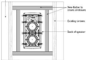
Fig 11: Stud partition under contraction – timber centers over 18°
Inside wall, viewed from rear
Rear of stud Rear of stud
Fig 12: Stud partition or wall cavity, using compliant material of appropriate thickness to create a light seal
Wstep

IV Series
Quick Star Guide
81
natural_image
Diagram of a speaker assembly showing components from an open case to a speaker, with no visible text or symbols.iW 6DS-WH
natural_image
Exploded view diagram of a speaker assembly showing sound waves, microphone, and speaker components (no text or labels)iW 62DS-WH
natural_image
Diagram of a speaker system showing front, side, and back views with sound waves and components (no text or labels)iW 625-WH
Subwoofer scenny 2 x 6" (bially)

natural_image
Diagram showing sound wave propagation from speaker to speaker array (no text or symbols)iW62 Backcan
natural_image
Close-up of a mechanical assembly with cylindrical components and mounting base (no visible text or symbols)Fig. 5 Clamps in the pre-install position (rest)

natural_image
Mechanical assembly diagram showing a lever and shaft assembly (no text or symbols visible)Fig. 6 Clamps in the install position
Pozycjonowanie
natural_image
Technical diagram of a mechanical assembly with central disc and surrounding components (no visible text or labels)Fig. 7 Changes in the pre-install position (W-ADC shown)
natural_image
Cross-sectional diagram of a mechanical or electrical component with no visible text or symbolsFig. 8 Clamps in the install position (W4DC)
Inside of stud partition viewed from rear

Fig 10: Stud partition under construction - 16* timber centers

natural_image
Exterior view of a rectangular wall-mounted device with mounting holes (no text or symbols visible)Fig. 8 IW 62DS and IW 62S Grille Detail
Inside of stud partition viewed from rear
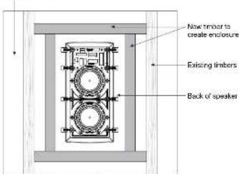
Fig 11: Stud partition under contraction – timber centers over 16°
Inside wall, viewed from rear
Rear of stud Rear of stud
Fig 12: Stud partition or wall cavity, using compliant material of appropriate thickness to create a light seal
導入
Quick Star Guide 89
製品機能の識別
IW 4DC-WH
natural_image
Exploded view diagram of a speaker assembly showing components like lens, frame, and speaker (no text or labels)iW 6DS-WH
natural_image
Exploded view diagram of a speaker system showing sound wave, screen, and speaker components (no text or labels)iW 62DS-WH
natural_image
Diagram of a speaker system with two speakers and a multi-noise speaker, showing sound wave propagation (no text or labels)iW62S-WH について
natural_image
Diagram showing sound wave propagation through a speaker array with two speakers and a blue flag marker (no text or symbols)90 IV Series
Quick Star Guide 91
iW62 バックカン
natural_image
Close-up of a mechanical assembly with cylindrical components and mounting base (no visible text or symbols)Fig. 5 Clamps in the pre-install position (rest)
インストール
natural_image
Mechanical assembly diagram showing a lever and shaft assembly (no text or symbols)Fig. 6 Clamps in the install position
绘画
natural_image
Technical diagram of a mechanical assembly with central rotating component and surrounding components (no visible text or labels)Fig. 7 Clampa in the pre-install position (W 4DC shown)
natural_image
Diagram of a mechanical or electronic component with central circular structure and surrounding components (no visible text or symbols)Fig. 8 Clamps in the install position (W 4DC)
グリルの取り付けと取り外し
Fig 10: Stud partition under construction - 16 timber centers
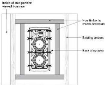
Fig 11: Stud partition under construction – timber centers over 16"
スピーカー負荷音 量 (続き)
オプション2
Inside wall, viewed from rear
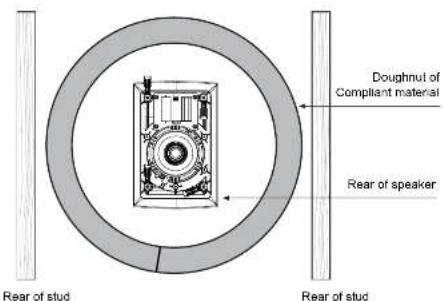
Fig 12: Stud partition or wall cavity, using compliant material of appropriate thickness to create a tight seal
介绍
98 TV Series
Quick Star Guide 99
产品特征识别
iW 4DC-WH
2路4英寸双同心入墙式扬声器 白色)
natural_image
Exploded view diagram of a speaker assembly showing components like case, lens, and speaker (no text or labels)iW 62DS-WH
3路6英寸入墙式扬声器 白色
natural_image
Exploded view diagram of a speaker assembly showing sound waves, speaker chamber, and speaker base (no text or labels)iW 625-WH
2×6英寸入墙式低音炮 白色)
natural_image
Diagram of a speaker system showing sound waves, lens components, and speaker output (no text or labels)iW 62S-WH
2×6英寸入墙式低青炮 白色)

natural_image
Diagram showing sound wave propagation from speaker to speaker array (no text or symbols)iW62 后盖
natural_image
Close-up of a mechanical assembly with cylindrical components and mounting base (no visible text or symbols)Fig. 5 Clamps in the pre-install position (rest)
natural_image
Mechanical assembly diagram showing a lever and shaft assembly (no text or symbols visible)Fig. 6 Clamps in the install position
102 W/ Series Quick Start Guide 103
定位
natural_image
Technical diagram of a mechanical assembly with central disc and surrounding components (no visible text or labels)Fig. 7 Claims in the pre-install position (in ADC shown)
natural_image
3D mechanical assembly diagram showing a central rotating component with surrounding components (no text or symbols visible)Fig. 8 Clamps in the install position (W 4DC)
格栅安装与拆卸
Fig 10: Stud partition under construction - 16" limber centers
natural_image
Exterior view of a white rectangular appliance with black square buttons on both sides (no text or symbols visible)Fig. 8 IW 62DS and IW 62S Grille Detail
Inside of stud partition
viewed from rear
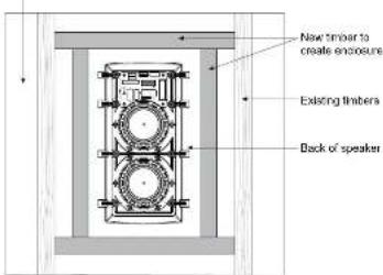
Fig 11: Stud partition under construction - limber centers over 16"
104 P/W Series Quick Start Guide 105
扬声器负载音量 续)
选项2
Rear of stud Rear of stud
Fig 12: Stud partition or wall cavity, using compliant material of appropriate thickness to create a tight seal
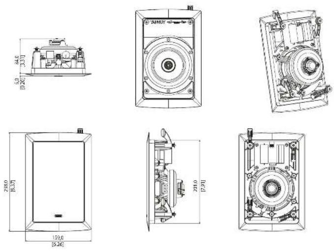
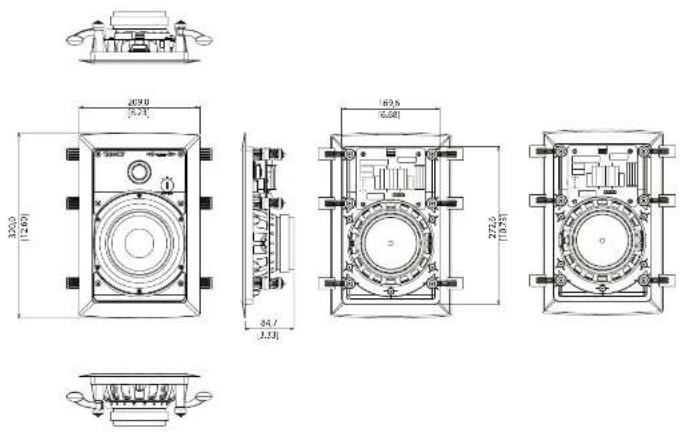
iW4 DC Model Dimensions
106 IW Series Quick Start Guide 107
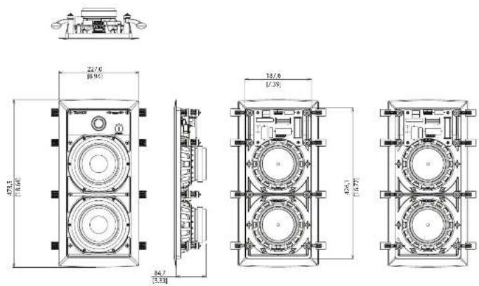
iW 6DS Model Dimensions
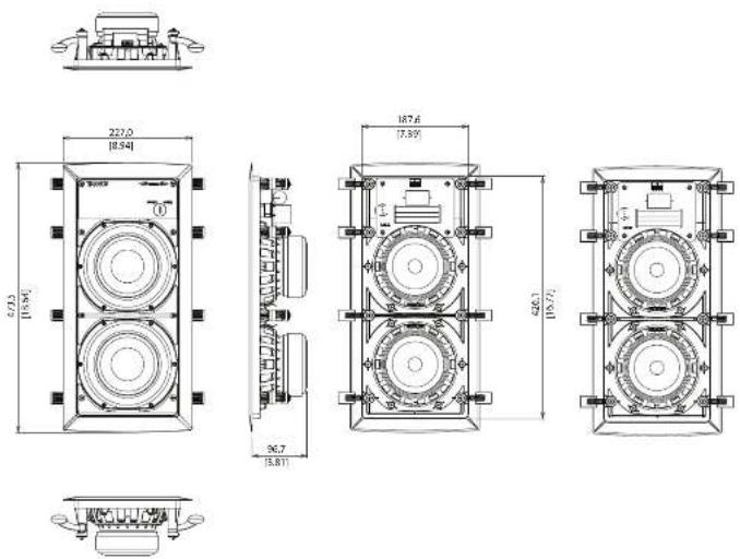
iW 62DS Model Dimensions
EN
108 IW Series Quick Start Guide 109
iW 625 Model Dimensions
Technical Specifications
EN
| MW 625-WH | MW 620S-VH | MW 60S-VH | MW 40C-VH | MW 62 BACKCAN | |
| Performance | |||||
| Frequency response(≥3 dB) (see note 3) | Passive: 29 Hz - 110 Hz;Actuar determinedby controller | 70 Hz - 20 kHz /5 Hz | 20 kHz 83 Hz - 51 kHz | ||
| Frequency response(-10 dB) | 34 Hz - 30 kHz / 36 Hz | 20 kHz 73 Hz - 54 kHz | |||
| Low frequencyalignment (-6 dB) | 25 Hz -34 Hz 36 Hz /3 Hz | ||||
| Power handling(see note 1) | 162 W continuous,640 V peak | 80 V continuous,320 V peak | 70 V continuous,280 V peak | 62 W continuous,240 W peak | |
| Recommendedamplifier power | 100~320 W (total: 20~ | 160 V @ 8.20 - 140 V @ 8.0 | 20~120 V @ 8.0 | ||
| System sensitivity(see note 2) | 94 dB (2.83 V @ 1 m) | 32 dB (2.83 V @ 1 m) | 89 dB (2.83 V @ 1 m) | 88 dB (2.83 V @ 1 m) | |
| Nominal Impedance | 4.0 | 8.0 | |||
| Rated maximum SPL | 116 dB continuous,122 dB peak | 111 dB continuous,117 dB peak | 107 dB continuous,113 dB peak | 106 dB continuous,112 dB peak | |
| Crossover | Passive, 2nd orderlow pass | Passive, 2nd order LF, 1stand 2nd order hand-passmid, 2nd order HF | Passive, 2nd order LF,2nd order HF | Passive, 2nd order LF,2nd order HF | |
| Crossover point | Passive: 110 Hz; Actuar:determined by controller | 500 Hz, 1.5 kHz | 1.7 MHz | 1.7 MHz | |
| Crossover HFadjustment | NA +15 dB | +15 dB | NA | ||
| Transducers | ||||
| High frequency | 25 mm (1.5" 25-meter stairium dome, nocyrium magnet system) | 19 mm (0.75" stairium dome, nocyrium magnet system | ||
| Low frequency | 2 x 165 mm (8.5") multifibre paper pulp cone | 165 mm (8.5") multifibre paper pulp cone | 100 mm (4.0") multifibre paper pulp and bass cone | |
| Wiring | Positive, positive 2,negative 1,negative 2 | Positive 1F, positive 1F,negative 1F, negative 1F, ground | Positive, negative, ground | Positive, negative |
| Physical | |||||
| Dimensions HWD | 473.5 x 227 x 110.5 mm(18.3 x 8.9 x 6.4") | 473.5 x 227 x 92 mm(18.6 x 8.9 x 3.6") | 320 x 209 x 90 mm(12.6 x 8.2 x 3.5") | 238 x 159 x91mm (5.4 x 6.3 x 3.6") | 1300 x 451 x 97 mm(47.2 x 17.8 x 3.8") |
| Mounting depth | 102 mm (ft) | 99 mm (3.5") | 88 mm (3.4") | ||
| Net weight | 5.8 kg (7.3 lb) | 4.2 kg (9.3 lb) | 7.3 kg (4.9 lb) | 1.3 kg (2.9 lb) | 8.6 kg (9.0 lb) |
| Construction | Baffle panel moulded UV Resistant ABS, Clamps moulded polycarbonate | Cabinet panel: SICC | |||
| Finish | White paintable | ||||
| Grille | Powder coated perforated steel | ||||
Notes:
1. Long-term power handling capacity as defined in IC standard EC601-5
2. Averaged over-specified bandwidth for half-space environment. For an electric condition, the figure is to be decreased by 3 dB
1. +348, measured at 1 metre in anchor chamber in critically tuned procedure.
4. Lenoxelins abenbi-amping bi-bi-ning
5. Remove links in stereo operation
110 W/ Series Quick Scan Guide 111
技术规格
Other important information

Important information
- Register online. Please register your new Music Tribe equipment right after you purchase it by visiting muscthe.com. Registering your purchase using our simple online team helps us to process your repair claims more quickly and efficiently. Also, read the terms and conditions of our warranty, if applicable.
- Malfunction. Should your Music Tribe Authorized Seller not be located in your vicinity, you may contact the Music Tribe Authorized Fuller for your country listed under "Support" at musictribe.com. Should your country not be listed, please check if your problem can be dealt with by our "Online Support" which may also be found under "Support" at musictribe.com. Alternatively, please submit an online warranty claim at musictribe.com BEFORE returning the product.
- Power Connections. Before plugging the unit into a power socket, please make sure you are using the correct mains voltage for your particular model. Faulty fuses must be replaced with fuses of the same type and using without exception.

Other important information

Responsible Party Name: Music Tribe Commercial NV Inc. Address: 122 E. 42nd St.1,
8th Floor NY, NY 10168, United States
Email Address: legal@musictribe.com
iW Series
This equipment has been tested and found to comply with the limits for a Class B digital device, pursuant to part 15 of the FCC Rules. These limits are designed to provide reasonable protection against harmful interference in a residential installation. This equipment generates, uses and can locate radio frequency energy and, if not installed and used in accordance with the instructions, may cause harmful interference to radio communications. However, there is no guarantee that interference will not occur in a particular installation. If this equipment does cause harmful interference to radio or television reception, which can be determined by turning the equipment off and on, the user is encouraged to try to correct the interference by one or more of the following measures:
- Reorient or relocate the receiving antenna.
- Increase the separation between the equipment and receiver.
- Connect the equipment into an outlet on a circuit different from that to which the receiver is connected.
- Consult the dealer or an experienced radio/TV technician for help.
This equipment complies with Part 15 of the FCC rules. Operation is subject to the following two conditions:
(1) this device may not cause harmful interference, and (2) this device must accept any interference received, including interference that may cause undesired operation.
Important information:
Changes or modifications to the equipment not expressly approved by Music Tribe can void the user's authority to use the equipment.
CE
Hereby, Music Tribe declares that this product is in compliance with General Product Safety Regulation (EU) 2003/988, Directive 2011/05/EU and Amendment 2015/863/EU, Directive 2012/19/EU, Regulation 519/2012 BLACH/SWHC and Directive 1957/2006/EU, and this passive product is not applicable to EMK Directive 2014/30/EU, LV Directive 2014/35/EU.
Full test of EU DoC is available at https://community.munitribe.com/
EU Representative: Music Tribe Brands DK A/S
Address: Gammel Strand 44, DK-1202 Kebenhawn K, Denmark
UK Representation: Music Tribe Brands UK Ltd.
Address: 3 ^th Floor, 20 Farringdon Street London EC4h 44B, United Kingdom
Correct disposal of this product: This symbol indicates that this product must not be disposed of with household waste, according to the WEE Directive (2012/19/EU) and your national law. This product should be taken to a collection center licensed for the recycling of waste electrical and electronic equipment (EEF). The mishuffling of this type of waste could have a possible negative impact on the environment and human health due to potentially hazardous substances that are generally associated with EEF. At the same
time, your cooperation in the correct disposal of this product will contribute to the efficient use of natural resources. For more information about where you can take your waste equipment for recycling, please contact your local city office, or your household waste collection service.