
MERCURY V4i - Loudspeaker TANNOY - Free user manual and instructions
Find the device manual for free MERCURY V4i TANNOY in PDF.


| Product Type | Bookshelf / Standmount Loudspeaker |
| Brand | Tannoy |
| Model | MERCURY V4i |
| Dimensions (W x H x D) | 210 x 350 x 280 mm |
| Weight | 8.2 kg |
| Frequency Response | 45 Hz - 35 kHz |
| Sensitivity | 89 dB (2.83V @ 1m) |
| Impedance | 8 Ohms |
| Recommended Amplifier Power | 25 - 150 W |
| Driver Configuration | 2-way, dual concentric driver (6.5" bass/mid, 1" tweeter) |
| Crossover Frequency | 2.5 kHz |
| Enclosure Type | Rear ported bass reflex |
| Connectors | Gold-plated binding posts (bi-wire compatible) |
| Power Handling (RMS) | 100 W |
| Power Handling (Peak) | 200 W |
| Grille | Magnetic, removable |
| Finishes Available | Black Ash, Walnut, Cherry |
| Placement | Bookshelf or standmount, avoid corners for bass tuning |
| Recommended Room Size | 15 - 30 m² |
| Supplied Accessories | User manual, rubber feet, grille |
Frequently Asked Questions - MERCURY V4i TANNOY
User questions about MERCURY V4i TANNOY
0 question about this device. Answer the ones you know or ask your own.
Ask a new question about this device
Download the instructions for your Loudspeaker in PDF format for free! Find your manual MERCURY V4i - TANNOY and take your electronic device back in hand. On this page are published all the documents necessary for the use of your device. MERCURY V4i by TANNOY.
USER MANUAL MERCURY V4i TANNOY
MERCURY Vi
CONTENTS
WARRANTY 02 CONNECTION V1i, VCi & VRi 04
INTRODUCTION 03 CONNECTION V4i 05
AMPLIFIER CHOICE 03 POSITIONING & FINE TUNING 06
CABLE CHOICE 03 GRILLES 06
UNPACKING 03 CARE OF CABINET 06
V4i FLOOR STANDING MODELS 03 MERCURY Vi HOME THEATRE 5.1 07
V1i, VCi & VRi MODELS 04 TECHNICAL SPECIFICATIONS 08
INSTALLATION 04 SET-UP DIAGRAMS 09-11
WARRANTY
No maintenance of the Mercury Vi loudspeaker is necessary.
As part of the MUSIC Group, Tannoy is committed to providing the highest quality products, service and user experience for our customers. One element of this commitment is our after sales support which now incorporates our extended Limited Warranty. In the event of any concern that is not addressed by this extended Limited Warranty we would ask you to contact us at care@music-group.com
For full warranty details including the extended Limited Warranty, please visit
http://www.music-group.com/warranty.aspx and register your purchase online at www.music-group.com or www.tannoy.com
INTRODUCTION
Thank you for selecting Tannoy loudspeakers, developed in the UK by our dedicated team of design engineers. They are the choice of discriminating music lovers the world over. Musical excellence is designed into our loudspeakers from the start. Careful selection of the very best components combined with strict quality control procedures in the production process ensures this level of excellence is maintained.
To gain maximum performance from your loudspeakers, please take time to read this owner's manual in full before installation. Once you have set up your new loudspeakers please register them on our website - this does not limit your legal rights.
Loudspeakers are electromechanical devices that 'run-in' through use; performance will therefore improve after an initial period of 24hrs use. Once they have been further run-in over a longer period, there will be clear enhancement of the stereo imaging, mid-band quality and bass performance characteristics.
We are confident that you will continue to enjoy your new Tannoy Mercury Vi loudspeakers for many years to come.
AMPLIFIER CHOICE
Consult the product specification pages within this manual as this clearly shows the acceptable power range for amplifier matching to your speakers. The high peak power handling of Tannoy loudspeakers permits responsible use with more powerful amplifiers - please read the Warranty.
As with all loudspeaker systems, the power handling is a function of voice coil thermal capacity. Care should be taken to avoid overdriving any amplifier, as this will cause output overload resulting in 'clipping' or distortion within the output signal. This will cause damage to the speakers if done for any extended period.
Generally an amplifier of higher power that is running hard, but free of distortion, will do less damage to the loudspeaker than a lower power amplifier continually clipping. Remember also that a high powered amplifier running at less than 90% of output power generally sounds a great deal better than a lower powered example struggling to achieve 100%. An amplifier with insufficient drive capability will not allow the full performance of the loudspeakers to be realised.
CABLE CHOICE
Always use the best quality of cable available within your budget. High quality audio signals passing from the amplifier to the loudspeaker are unusual in their demands on the cable. Wide dynamic range and frequency bandwidth information has to coexist with the ability to transmit peak currents of at least 10 amps, without incurring any loss or signal impairment. This explains why the sound quality of the information reproduced by the loudspeakers is so dependant on the physical properties of the cables connecting them to the amplifier.
We would recommend that you always keep the cable runs the same length for each speaker. Remember that cable construction can affect the sound quality so be prepared to experiment to find a cable that suits your ear and audio system.
UNPACKING
To unpack the loudspeakers from their boxes remove tape from the top then fold the flaps right back before inverting the carton and contents. Lift the carton clear of the contents then remove all inner packaging.
It is strongly recommended that you store all the packaging to allow protected transportation in future.
V4i FLOOR STANDING MODEL
The Mercury V4i performs best with carpet piercing spikes fitted, together with the plinth assembly provided. Referring to fig. 1, screw the plinth sections securely to the underside of the cabinet, taking care not to over tighten. The spikes with lock nuts should then be inserted into the threaded holes in the plinth. Level the speakers and then tighten the lock nuts firmly but without using undue force. Spike locating cups are provided in the accessory pack and these may be used to protect sensitive floor surfaces. (See fig. 1)
WARNING:
Ensure that the spikes are levelled and that the lock nuts are tightened firmly. The spikes should be pushed through the carpet to locate into the flooring surface by applying pressure to the top of the cabinet.
If using on a sensitive floor surface place the protective cups under the levelled spikes. Failure to do so could render the speaker unsteady and result in damage or injury should it be knocked over.
V1i, VCi & VRi MODELS
Stand mounting or bookshelf speakers should be located securely on stands or a shelf in an appropriate position to place high frequency unit roughly at ear height when seated in the chosen listening position. Positioning recommendations for stand-mounted speakers can be found under the section entitled Positioning and fine-tuning.
The Mercury V1i and VCi may also be wall mounted with a suitable bracket, using two inserts on the rear of the loudspeaker, with standard 60 mm spacing. The thread in the inserts is M5. It is the responsibility of the customer to ensure the chosen bracket is used within its load rating, and the bracket is securely mounted to the wall with suitable hardware.
The Mercury VRi is provided with integral hanging plates for wall mounting.
INSTALLATION
To avoid potential damage to your loudspeaker, ensure that the amplifier is switched OFF prior to connecting or disconnecting any cables. Before switching on double check that all connections are secure and that polarity is correct.
CONNECTION V1i, VCi & VRi
The positive (plus) terminal on the amplifier left channel (marked + or coloured red) must be connected to the positive HF terminal on the left speaker. The left speaker is the one on the left as you look at the stereo pair from your listening position.
The negative (minus) terminal on the amplifier left channel (marked - or coloured black) must be connected to the negative HF terminal on the left speaker.
Repeat this connection process for the right speaker. Remember that the positive (+ or red) on the amplifier must be connected to the positive (+ or red) on the speaker and the negative (- or black) to negative.
Select a signal source, such as a CD player; switch on the amplifier and slowly turn up the volume control to check that both loudspeakers are reproducing bass and treble information. (See fig. 2)
CONNECTION V4i
Single Wire Mode:
The terminal panels have captive link bars fitted as standard to link the positive and negative HF and LF terminals respectively. These must be removed to Bi-Wire the speakers - see section entitled Connection in Bi-Wire mode. (See fig. 2)
For optimum performance in single wire mode, loudspeaker cable connections from the amplifier should be made to the high frequency (HF) terminals of the loudspeaker:
Connect as instructed above for V1i, VCi & VRi. (See fig. 3)
Bi-Wire Mode:
Please note in Bi-Wire mode that the link bars must be removed. Unscrew the knurled nuts on both the positive and negative HF and LF terminals and remove the link bar and then replace the colour coded nuts, as they will be required to clamp the Bi-Wire cables in place. Retain the link bars in a safe place for possible future use.
Be sure that the amplifier is switched off and then prepare the two sets of cabling for each 'side' of the system separately. Measure and cut four lengths of cable, two per speaker.
Label two of the cable lengths Left LF and Left HF (low frequency and high frequency) then repeat this process for the right pair.
If your amplifier is not equipped with separate output terminals for bass and treble information then, at the amplifier end of the cables, twist the Left LF+ (positive) and the Left HF+ (positive) together. Connect these to the amplifier Left channel positive terminal marked + (plus) or coloured red.
Twist the Left LF- (negative) and the HF- (negative) cables together and connect them to the amplifier Left channel negative terminal marked - (minus) or coloured black.
At the loudspeaker end connect the cables labelled Left LF+ and Left LF- to the left hand loudspeaker LF terminals, ensuring that you note the polarity markings on the cable sheathing.
Then proceed to connect the Left HF+ and Left HF- to the HF terminals on the same loudspeaker.
Repeat this process to connect the right hand loudspeaker to the amplifier right channel output, once again ensuring that polarity is correct throughout.
Switch the amplifier on with the volume control set at its lowest setting. Select a favourite source and slowly turn up the volume to a low level. Check that bass and treble information is being reproduced from both speakers - if not, switch off the amplifier and recheck the connections. (See fig. 4)
Bi-Amp Mode:
Bi-Amping extends the principle of Bi-Wiring one stage further. In this connection option separate power amplifiers are used for bass and treble signals in each loudspeaker. Four mono (or two stereo) amplifiers of the same type are required for a stereo pair of loudspeakers. Ensure that the cable links between the loudspeaker terminals are removed and that correct polarity is maintained throughout.
If two stereo amplifiers are used, it is recommended that one amplifier supply bass information to left and right loudspeakers and the other, the treble information. (See fig. 5)
POSITIONING AND FINE-TUNING
To get best results from your new Tannoy Mercury Vi loudspeakers it is worthwhile spending a little time finding the optimum set-up configuration.
Begin by angling the speakers towards your chosen listening position, usually this is on the centre line of the room, so that when seated you can just see the inner side panel of each speaker. The front of the loudspeaker should not be obstructed in any way. The loudspeakers should be located between 1.5 to 4.5 metres (5 ft to 15 ft) apart - with the listening position set slightly further away than the speakers are apart. Avoid positioning the loudspeakers in corners of the room, as this will have a negative effect on performance. For optimum performance, we would recommend ideally maintaining a distance of at least 0.5 metres (20 inches) from the rear wall, and 1 metre (39 inches) from the side. However, there is no absolute right or wrong as it is much down to personal preference and the differing sizes and acoustic properties of the listening environment. The speakers may be located close to the rear wall, in which case bass will be increased at the expense of definition, and stereo soundstaging will be compromised. (See fig. 6)
For the floor standing V4i model in its listening position, rock the loudspeaker gently from side to side so that the spikes find their way through the weave of the carpet and on to the solid surface below. Once fine adjustments have been made to the spikes, to level the loudspeaker and ensure stability, tighten the lock nuts firmly but without using undue force.
GRILLES
The Mercury Vi grille has been designed to provide acoustic transparency. However, for ultimate fidelity the enthusiast will appreciate the slight improvement in clarity and detail that is achieved by removing the grilles during listening.
CARE OF CABINET
The cabinets should only be cleaned with a dry cloth or with a light application of quality non-silicone furniture polish.
Mercury Vi HOME THEATRE 5.1 - GENERAL INFORMATION
Unlike other forms of encoded surround audio, 5.1 offers full bandwidth capability for the surround and centre channels, with the ability to treat the subwoofer as a single discreet channel for special effects playback or, for music applications, as a dedicated low frequency instrument channel. This places new demands on the surround and centre channel loudspeakers in both the mixing environment and the playback environment.
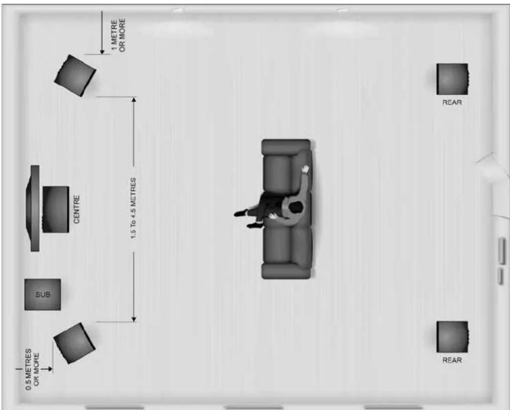
The 5.1 format allows the mix engineer in the recording studio to assign audio information to one or more discreet channels of playback; providing very vivid and exacting localisation for the apparent sound sources in the listening environment. To reliably recreate that accurate localisation during playback, the selection and location of loudspeakers becomes the single most critical issue next to the talent of the mix engineer in the studio. (See fig. 7)
MAGNETIC SCREENING
The large magnet assemblies on the loudspeaker drive units of the V1i, V4i and VCi models are fully screened to eliminate colour-fringing effects when mounted close to CRT television monitors, but very sensitive models may show some fringing. If that occurs, move the speaker further away from the television monitor. However, the VRi model is unscreened, and should not be placed closer than 1 metre (3ft) from a CRT display.
Note that plasma and LCD displays are not affected by magnetic fields, so there is no restriction on placement.
FRONT SPEAKERS
The ultra wide dynamic range and power handling capability of Mercury Vi loudspeakers will provide a stunning home cinema experience. The speakers should be positioned on either side of the TV or projection screen and then placed in line with the screen surface.
CENTRE CHANNEL SPEAKER
In all cases the centre channel speaker should be positioned as near to the TV screen as possible. The viewing position when seated determines the ideal mounting height, but in all cases this should be as close as possible to ear height (or angled towards ear height). As with the main speakers the front baffle panel should be as near as possible in line with the screen surface.
REAR SPEAKERS
The placement of rear speakers should ideally mirror that of the front speakers as far as possible, behind the main viewing position.
If wall or shelf mounted however, they should be 1.5 to 4.5 metres apart (5 to 15 ft), with a mounting height (to the tweeter) of 1.5 to 2 metres (5 to 7 ft).
SUBWOOFER
As the subwoofer only produces low frequency, therefore monaural information, it is difficult to detect its location by ear. It could as a result be situated anywhere in the room, but optimum performance will be gained by locating the subwoofer between the main stereo pair of speakers. Bass output will increase when placed next to a wall or in a corner so use the subwoofer volume control to balance the output with the rest of the system.
The Tannoy TS range of subwoofers would be an ideal partner for your Mercury Vi home theatre system. Designed to excel in speed and power, each model uses a digital amplifier and two large, long-throw drivers to deliver extremely fast and deep bass and achieve considerable LFE output from a compact cabinet.
Two performance options are available, both utilising class D bridge mode amplifiers - 300 Watt RMS with twin 10" drivers on the TS2.10 and 500 Watt RMS with twin 12" drivers on the TS2.12. The TS2 cabinets are built from heavyweight 25 mm MDF throughout, substantially reducing cabinet colouration and adding valuable extra mass for stabilisation.
Please visit the Tannoy website (www.tannoy.com) for more detailed information on the TS2 subwoofers and refer to the manual supplied with the subwoofer for advice on installation and set-up.
TECHNICAL SPECIFICATIONS
Mercury V1i Mercury V4i Mercury VRi Mercury VCI
PERFORMANCE
| Recommended amplifier power 10 - 70 10 - 140 10 - 60 10 - 90 (Watts RMS) | ||||
| Continuous power handling 50 100 40 70 (Watts Peak RMS) | ||||
| Peak power handling (Watts) | 100 | 200 80 140 | ||
| Sensitivity (2.83 Volts @ 1 m) | 86 dB | 91 dB | 86 dB | 90 dB |
| Nominal Impedance (ohms) | 8 | 8 | 8 | 8 |
| Frequency response (-6 dB) | 45 Hz – 53 kHz | 32 Hz – 53 kHz | 57 Hz – 53 kHz | 67 Hz – 53 kHz |
DRIVE UNITS
| High frequency | 25 mm (1.00")Aluminium dome neodymium magnet system | 25 mm (1.00")Aluminium dome neodymium magnet system | 25 mm (1.00")Aluminium dome neodymium magnet system | 25 mm (1.00")Aluminium dome neodymium magnet system | |
| system | system | ||||
| Low frequency | 130 mm (5.00")Multi-fibre coated pulped paper cone | 2 x 152 mm (6.00")Multi-fibre coated pulped paper cone | 130 mm (5.00")Multi-fibre paper cone | 2 x 100 mm (4.00")Multi-fibre paper cone | |
| coated pulped | coated pulped | ||||
| Shielded | Yes | Yes | No | Yes | |
CROSSOVER
| Crossover frequency | 3.2 kHz | 2.6 kHz | 3.2 kHz | 2.9 kHz |
| Crossover type acoustic | 4th orderacoustic acoustic acoustic Linkwitz-Riley | Bi-Wirable 4th order | 4th order | 4th order |
| Linkwitz-Riley | Linkwitz-Riley | Linkwitz-Riley |
CABINET
| Enclosure type | Front reflex | Rear reflex | Front reflex | Twin rear reflex |
| Constructioncross-braced cross-braced | 15 mm particle board, internally cross-braced enclosure 18 mm MDF front baffle | 15 mm particle board, internally cross-braced enclosure 18 mm MDF front baffle | 15 mm particle board, internally enclosure 18 mm MDF front baffle | 15 mm particle board, internally enclosure 18 mm MDF front baffle |
| Dimensions (inc grille) H x W x D | 300.0 x 170.0 x 254.5 mm (11.81 x 6.69 x 10.02") | 995.4 x 204.0 x 281.0 mm (39.19 x 8.03 x 11.06") | 300.0 x 170.0 x 121.5 mm (11.81 x 6.69 x 4.78") | 140.0 x 430.0 x 170.0 mm (5.51 x 16.93 x 6.69") |
| Volume - litres (cubic feet) | 7.8 (0.28) | 38.5 (1.36) | 2.8 (0.10) | 5.5 (0.19) |
| Weight | 4.5kg (9.9 lbs) | 14.7kg (32.4 lbs) | 2.6kg (5.7 lbs) | 4.9kg (10.8 lbs) |
| Finish Dark Walnut | Sugar Maple Dark Walnut Dark Walnut | Sugar Maple Sugar Maple Dark Walnut | Sugar Maple Sugar Maple |
SET-UP DIAGRAMS
Fig. 1 V4i Plinth Assembly
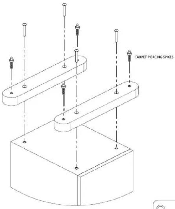
Fig. 2 Connection V1i, VCi and VRi

Fig. 3 Connection V4i, Single Wire Mode

LINKS IN PLACE
SET-UP DIAGRAMS
Fig. 4 Connection V4i Bi-Wire Mode

Fig. 5 Connection V4i Bi-Amp Mode

SET-UP DIAGRAMS
Fig. 6 Recommended Positioning - Stereo Pair
![graph TD A["Room 1: 0.5 METRES OR MORE"] --> B["Room 2: 1.5 To 4.5 METRES"] B --> C["Room 3: ONE METRE OR MORE"] B --> D["Room 4: 0.5 METRES OR MORE"] style A fill:#f9f,stroke:#333 style B fill:#ccf,stroke:#333 style C fill:#cfc,stroke:#333 style D fill:#fcc,stroke:#333](/content/2026/06/1293584/images/3c6563d036e8a123146113667de6c21dca4dfe2a0982dae8bbf1bfe32d2987a6.jpg)
Fig. 7 Recommended Positioning - Home Cinema
Tannoy operates a policy of continuous research and development. The introduction of new materials or manufacturing methods will always equal or exceed the published specifications. All specifications are subject to change without notice. Copyright (c) 2015 Music Group Innovation SC Ltd. All rights reserved.




- MERCURY VI
- CONTENTS
- WARRANTY
- INTRODUCTION
- AMPLIFIER CHOICE
- CABLE CHOICE
- UNPACKING
- V4I FLOOR STANDING MODEL
- WARNING
- V1I, VCI & VRI MODELS
- INSTALLATION
- CONNECTION V1I, VCI & VRI
- CONNECTION V4I
- SINGLE WIRE MODE
- BI-WIRE MODE
- BI-AMP MODE
- POSITIONING AND FINE-TUNING
- GRILLES
- CARE OF CABINET
- MERCURY VI HOME THEATRE 5.1 - GENERAL INFORMATION
- MAGNETIC SCREENING
- FRONT SPEAKERS
- CENTRE CHANNEL SPEAKER
- REAR SPEAKERS
- SUBWOOFER
- TECHNICAL SPECIFICATIONS
- SET-UP DIAGRAMS
Brand : TANNOY
Model : MERCURY V4i
Category : Loudspeaker