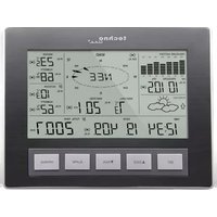
WS 2816 - Weather Station Techno Line - Free user manual and instructions
Find the device manual for free WS 2816 Techno Line in PDF.


| Product type | Wireless professional weather station |
| Brand | Techno Line |
| Model | WS 2816 |
| Display dimensions | 222 x 42 x 173 mm |
| Thermo-hygro sensor dimensions | 79,4 x 89,8 x 189,3 mm |
| Wind sensor dimensions | 250 x 145,9 x 282,2 mm |
| Rain sensor dimensions | ∅ 131,6 x 182,7 mm |
| Display power supply | 3 C batteries (LR14, 1,5 V) |
| Thermo-hygro sensor power supply | 2 C batteries (LR14, 1,5 V) |
| Rain sensor power supply | 2 AA LR6 batteries |
| Wind sensor power supply | Solar panel + built-in rechargeable battery |
| Transmission frequency | 868 MHz |
| Transmission range (thermo-hygro to display) | Approximately 100 m (open area) |
| Transmission range (wind/rain sensors to thermo-hygro) | Approximately 50 m (open area) |
| Indoor temperature range | -40 °C to +59,9 °C |
| Outdoor temperature range | -40 °C to +59,9 °C |
| Humidity range (indoor and outdoor) | 1 % to 99 % |
| Wind speed range | 0 to 180 km/h (multiple units) |
| Precipitation range | 0 to 9999,9 mm |
| Relative pressure range | 920 to 1080 hPa |
| Main functions | Time/date, weather forecast (3 icons), indoor/outdoor temperature, humidity, dew point, wind chill, wind direction and speed, precipitation, pressure history (24h/72h), weather alarms (temperature, humidity, wind, pressure, rain, storm), min/max recording, storage of 1750 records, Heavy Weather Pro software for PC |
| Maintenance and cleaning | Clean with a slightly damp cloth, do not use solvent, do not immerse |
| Safety | Do not open, do not expose to shocks, keep out of reach of children, observe battery polarity |
| Repairability | Do not repair yourself, return to point of sale |
Frequently Asked Questions - WS 2816 Techno Line
User questions about WS 2816 Techno Line
0 question about this device. Answer the ones you know or ask your own.
Ask a new question about this device
Download the instructions for your Weather Station in PDF format for free! Find your manual WS 2816 - Techno Line and take your electronic device back in hand. On this page are published all the documents necessary for the use of your device. WS 2816 by Techno Line.
USER MANUAL WS 2816 Techno Line
THERMO-HYGRO-SENSOR: 5
WINDSENSOR: 5
REGENSENSOR: 6
GRUNDEINSTELLUNG: 6
THERMO-HYGRO-SENSOR: 10
HEAVY WEATHER PRO PC-SOFTWARE: 10
FUNKTIONSTASTEN: 10
natural_image
Line drawing of a missile or aircraft with two circular components and a tapered body (no text or symbols)natural_image
Pure technical line drawings of mechanical components without any text or symbolsnatural_image
Diagram of a propeller with three blades and a central hub, showing no text or symbols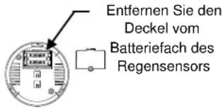
Regensensor: 2 x AA LR6
Wireless Professional Weather Center
Instructions Manual
TABLE OF CONTENTS
TABLE OF CONTENTS 35
INTRODUCTION 39
INVENTORY OF CONTENTS 39
FEATURES: 39
WIRELESS DISPLAY 40
THERMO-HYGRO SENSOR 40
WIND SENSOR 40
RAIN SENSOR 41
SETTING UP: 41
ADDITIONAL NOTES FOR THE SOLAR WIND AND RAIN SENSORS
MODES 42
MOUNTING THE SENSORS AND PLACEMENT OF THE WIRELESS DISPLAY:
43
WIND SENSOR 44
RAIN SENSOR 44
THERMO-HYGRO SENSOR 44
HEAVY WEATHER PC SOFTWARE 44
FUNCTION KEYS: 44
SET KEY 44
▲/DATE KEY 45
▼/RAIN KEY 45
ALARM KEY 45
MIN/MAX KEY 45
LCD SCREEN 45
MODE 1 DISPLAY: 46
MODE 2 DISPLAY: 46
MANUAL SETTINGS: 46
LCD CONTRAST SETTING 47
MANUAL TIME SETTING: 47
12/24 HOUR TIME DISPLAY SETTING: 48
CALENDAR SETTING: 48
°F/°C TEMPERATURE UNIT SETTING 49
WIND SPEED UNIT SETTING 49
RAINFALL UNIT SETTING 49
RELATIVE AIR PRESSURE UNIT SETTING 50
RELATIVE PRESSURE REFERENCE VALUE SETTING 50
WEATHER TENDENCY SENSITIVITY LEVEL SETTING 51
STORM WARNING THRESHOLD VALUE SETTING 51
STORM ALARM ON/OFF SETTING 52
WIND DIRECTION DISPLAY TYPE SETTING 52
FACTORY RESET PROCEDURE 53
TO EXIT THE MANUAL SETTING MODE 54
WEATHER ALARM OPERATIONS 54
THE FOLLOWING WEATHER ALARMS CAN BE ADJUSTED IN ALARM
SETTING MODE 54
DEFAULT WEATHER ALARM VALUES: 54
PRESSURE ALARMS 55
INDOOR TEMPERATURE ALARMS 55
INDOOR HUMIDITY ALARMS 56
OUTDOOR TEMPERATURE ALARMS 57
OUTDOOR HUMIDITY ALARMS 57
WIND GUST ALARM 58
WIND DIRECTION ALARM 58
24H RAINFALL ALARM 59
HYSTERESIS 59
WEATHER FORECAST AND WEATHER TENDENCY 60
WEATHER FORECASTING ICONS: 60
WEATHER TENDENCY INDICATOR 61
AIR PRESSURE HISTORY (ELECTRONIC BAROMETER WITH BAROMETRIC
PRESSURE TREND) 61
WIND DIRECTION AND WIND SPEED MEASUREMENT 62
RAINFALL MEASUREMENT 62
VIEWING THE MIN/MAX WEATHER DATA 63
RESET THE MINIMUM AND MAXIMUM WEATHER DATA 63
TOTAL RAINFALL AMOUNT 63
CARE AND MAINTENANCE: 63
DECLARATION OF CONFORMITY 64
SPECIFICATIONS: 64
INDOOR TEMPERATURE 64
OUTDOOR TEMPERATURE / DEW POINT 64
INDOOR HUMIDITY 64
OUTDOOR HUMIDITY 64
WIND SPEED/ GUST 64
WIND CHILL/ DEW POINT 65
RAINFALL (24H ; TOTAL) 65
OUTDOOR DATA RECEPTION 65
AIR PRESSURE 65
TRANSMISSION RANGE 65
DIMENSIONS (L X W X H) 65
LIABILITY DISCLAIMER AND SAFETY INFORMATION 66
INTRODUCTION
Congratulations on purchasing this state-of-the-art weather station. Featuring time, date, calendar, weather forecast, wind gust and wind speed, indoor/outdoor temperature and humidity, air pressure and rainfall, this weather station will provide you with various weather information and weather forecasts.
Heavy Weather Pro software allows you to use a PC to monitor and record weather data received from your wireless weather station via a proprietary USB device that was provided with your WS2816 weather station.
You can monitor and record a variety of data collected by your weather station including both indoor and external values sampled by the various weather station sensors.
You can also review weather history data, and analyze trends and tendencies over time using the software's charts and graphing features.
Download the free Heavy Weather Pro PC software at: www.heavyweather.info
INVENTORY OF CONTENTS
| Carefully open the package and check that the following contents are complete: | ||||
| Wind Sensor | Rain Sensor | Thermo-Hygro Sensor | Wireless display | USB Transceiver |
 Mast holderRight angle adaptor1 x U-bolts2 Washers + 2 NutsPlastic Reset Rod Mast holderRight angle adaptor1 x U-bolts2 Washers + 2 NutsPlastic Reset Rod | 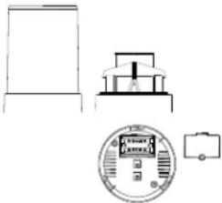 Base sensor, funnel top cover and battery cover (pre-assembled) Base sensor, funnel top cover and battery cover (pre-assembled) | 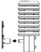 Rain protection coverWall mount adapterMounting screwsPlastic anchors for screws Rain protection coverWall mount adapterMounting screwsPlastic anchors for screws | 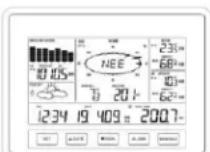 Display of data Display of data | 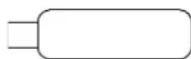 USB wireless interface for PC USB wireless interface for PC |
FEATURES:
WIRELESS DISPLAY
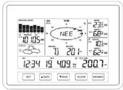
• Time display in 12/24 hour time format
- Automatic time and date (PC time) update from USB transceiver if connected
• Calendar display (date, month, year)
- Weather forecast with 3 weather icons (sunny, cloudy, and rainy) with weather tendency indicator
• Temperature display in °C/°F
• Humidity display in RH%
- Dew point display in °F/°C
• Wind chill display in °F / °C
- MIN/MAX values of indoor/outdoor temperature, indoor/outdoor humidity, dew point display with time and date of recording
- Relative air pressure reading in hPa/ inHg
• 24h/72h history graph selectable
• Wind speed displayed in km/h, m/s, mph, knots, and Beaufort scale
- Wind speed & direction with LCD compass display (16 steps/ 22.5 degree)
• MAX records for wind gust with time & date of recording
- Rainfall display in mm/inch
- Rainfall data for total rain, last hour, last 24h, last week, last month
- Weather alarm modes: temperature, humidity, wind gust, wind direction, air pressure, 24h rain and storm warning
- LCD contrast setting
- Storage of 1750 sets of weather records with user selectable recording interval from 1 minute to 24 hours
THERMO-HYGRO SENSOR
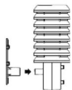
• Transmission of temperature and humidity data
- Transmission range: about 100 meters (Open field, free of obstructions)
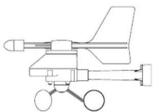
WIND SENSOR
natural_image
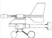
Line drawing of a missile launcher system with two wheels and an external rotor (no text or labels)- 100% solar-powered with built-in rechargeable alkaline power cell
- High-efficient solar panels maintain operation throughout all seasons
- Transmission range: about 50 meters (Open field, free of obstructions)
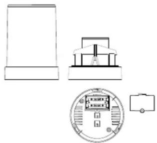
RAIN SENSOR
natural_image
Pure technical line drawings of mechanical components without any text or symbols- Powered by 2 x AA LR6 batteries
- Self-emptying bucket
- Transmission range: about 50 meters (Open field, free of obstructions).
SETTING UP:
IMPORTANT: Make sure to observe the correct polarity when inserting batteries. The "+" markings on the batteries must line up with the diagrams inside the battery compartments. Inserting the batteries incorrectly may result in permanent damage to the units. During the setup process, place the wireless display and the outdoor sensors on a surface with 1-3 meters between the sensors and the display. Only use Alkaline Batteries for the Wireless Display and Thermo-hygro sensor, rechargeable batteries may not work.
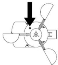
- It is important to allow sufficient light to reach the solar panel while activating the wind sensor. Make sure the lights are on in the setup room and the solar panel is facing a 60W light bulb or brighter - do not cover with hands or other objects. Remove the black protective foil on the solar panel and use the provided plastic reset rod to gently press the reset button once in the hole on the bottom of the sensor.
- Twist open the top of the rain sensor. Remove the securing tape from the seesaw. Install batteries. Swing the seesaw once to ‘wake-up’ the rain sensor. The rain sensor should then be placed under a clear environment.
IMPORTANT: Completely reset the rain sensor:
a. Unscrew the battery cover on bottom of the rain sensor and remove the batteries
b. Wait 20s, then re-insert the 2 x AA batteries and re-screw the battery compartment back
c. Swing the seesaw once and put the rain cover top back.
d. Place the rain senor under clear environment.
- Insert two "C" size batteries into the thermohygro sensor with the correct polarity.
- Insert three "C" size batteries into the wireless display with the correct polarity.
Press Reset Button on Bottom of the Wind Sensor (Solar Panel Must Face Light)
natural_image
Diagram of a propeller blade assembly with a downward arrow indicating compression or disassembly (no text or symbols present)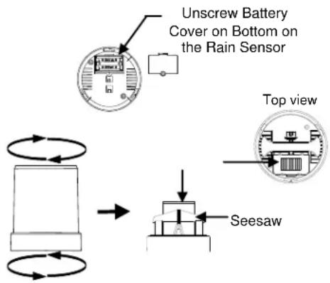
flowchart
graph TD
    A["Unscrew Battery Cover on Bottom on the Rain Sensor"] --> B["Top view"]
    B --> C["Seesaw"]
    C --> D["Bottom component with circular arrows indicating rotation or cycle"]
NOTE: Every time the wireless display receives data from the sensors, the wireless icons will blink once and then return to solid if the last transmission was successful. A wind speed or rainfall amount that reads "0" does not mean reception failure, it means that there was no wind or rain at the time of the last measurement. The thermo-hygro sensor syncs with the wind and rain sensors and sends all outdoor sensor data to the display. The thermo-hygro sensor tries for 7 minutes to sync to the wind sensor and for the rain sensor. If not successful within 7 minutes, the thermo-hygro sensor will stop looking for the other sensors.
- 5. Setup troubleshooting: If the sensor data fails to display for any of the outdoor sensors within 10 minutes, (“- - -” is displayed), remove the batteries from all units (except for the Wind Sensor) for 1 minute and start the Setup procedure again at Step 1 and completely reset the Rain Sensor (see Step 2: Important).
ADDITIONAL NOTES FOR THE SOLAR WIND SENSOR MODES:
IDLE MODE
This mode aims to reduce the power consumption of the transmitter. Under this mode, the sensor stops the transmission of signal, checks the battery voltage and detects the solar cell condition. The IDLE mode happens if the battery voltage is low.
Note: The sensor will check and charge up the rechargeable battery automatically. When it detects that the battery voltage is sufficiently charged up and high enough, the transmission of signal starts again.
STOP MODE
It is the most energy saving mode. Under this mode, the transmitter stops the transmission of signal. There is no checking of the battery voltage and no detection of the solar cell condition. The STOP mode happens:
- If the user covers the solar cell for 10 seconds and presses the RESET button (Wind Sensor).
- If the sensor(s) is(are) placed in the dark environment for 72 hours.
Note:
- To restart the Solar Wind sensor, user should spin the wind cups or place the sensor in a bright environment, then press the RESET button once to wake it up again.
- To restart the Rain Sensor, should swing the seesaw or, follow the SETTING UP, Step 2: Important instructions to completely reset the sensor.
IMPORTANT! During the restart process, if the battery voltage is sufficiently high enough, the transmission of signal starts again. However, if the battery voltage is low, the sensor(s) enters the IDLE mode. User should place the sensor(s) under a bright environment in order to charge up the rechargeable batteries.
MOUNTING THE SENSORS AND PLACEMENT OF THE WIRELESS DISPLAY:
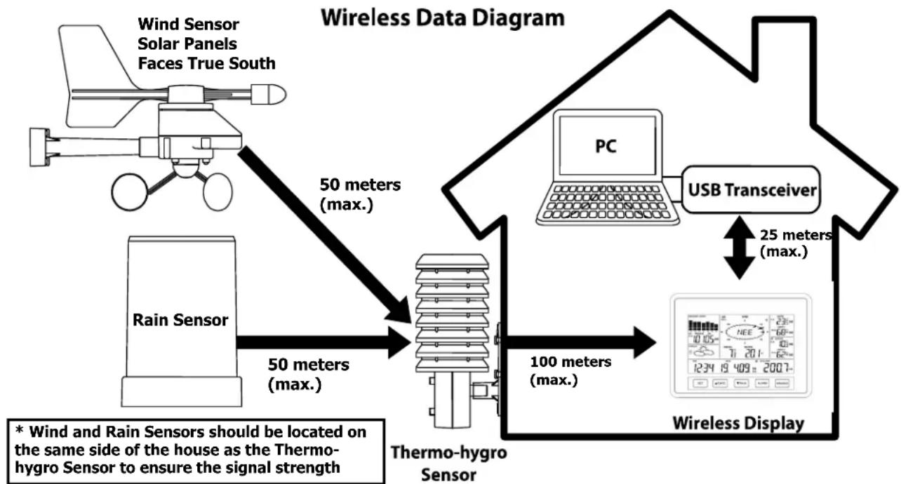
IMPORTANT: Ensure that all of the sensor data can be received at the intended mounting locations before you drill mounting holes. The outdoor sensors have a wireless range of 50 meters. Keep in mind that the 50 meters range equates to an open air scenario with no obstructions. Each obstruction (roof, walls, floors, ceilings, etc.) will reduce the range.
flowchart
graph TD
    A["Wind Sensor Solar Panels Faces True South"] -->|50 meters (max.)| B["Thermo-hygro Sensor"]
    C["Rain Sensor"] -->|50 meters (max.)| B
    B -->|100 meters (max.)| D["PC"]
    D -->|25 meters (max.)| E["USB Transceiver"]
    E --> F["Wireless Display"]
    style A fill:#f9f,stroke:#333
    style C fill:#f9f,stroke:#333
    style B fill:#ccf,stroke:#333
    style D fill:#cfc,stroke:#333
    style E fill:#fcc,stroke:#333
    style F fill:#cff,stroke:#333
The thermo-hygro sensor measures outdoor temperature & humidity and collects the data from the wind and the rain sensors and sends all outdoor weather data to the wireless display, so the thermo-hygro sensor must be within the 100 meters wireless range of the wireless display. This allows the wind and rain sensors to be placed relative to the thermo-hygro sensor rather than the wireless display. See Wireless Data Diagram above.
- The wind and rain sensors must be mounted within the 50 meters wireless range of the thermo-hygro sensor and on the same side of the house.
- The wireless display must be within the 25 meters wireless range of the USB transceiver to send weather data to the PC.
If the sensor wireless icons drop from the display as you move them into their intended locations, the sensors may be too far from the wireless display. Try moving the wireless display or the sensors closer and wait a few minutes to see if the wireless icons display again. If the wireless icons are still not displayed after re-positioning the sensors or the wireless display, press and hold the ▲UP ARROW key for 2 seconds to re-synchronize the wireless display with the sensors.
WIND SENSOR
The wind sensor must be installed with the front of the sensor (the solar panel) facing true South, or the reported wind direction will not be accurate. Mount within the 50 meters wireless range of the thermo-hygro sensor and on the same side of the house. The roof may or may not be an ideal mounting location. Secure the main unit to the shaft of the mast holder. Use the right-angle adaptor if the wind sensor will be mounted on a horizontal mast or surface.
Fasten the wind sensor to a suitable mast using the two U-bolts, washers and nuts included. Note: Mount the wind sensor onto a mast so the wind can reach the sensor unobstructed from all directions for an accurate reading. The ideal mast is between 15.75mm and 33mm in diameter. The wind sensor DOES NOT have replaceable batteries, it consumes solar power and charges the internal battery pack automatically.
RAIN SENSOR
The rain sensor should be mounted on a level surface in an open area and bright area within the 50 meters wireless range of the thermo-hygro sensor and on the same side of the house. Mount the rain sensor at least 0.30 meter off the ground level for optimum wireless transmission. The rain sensor should be accessible to allow for period cleaning of debris or insects.
THERMO-HYGRO SENSOR
The thermo-hygro sensor is "weather resistant", but not "water proof". To ensure an extended life of your sensor, mount it in a semi-covered place out of the elements. An ideal location for the thermo-hygro sensor is under the eaves on the North side of the house to avoid the effects of sunlight. Mount the sensor 0.5 meter down from the eaves to ensure optimum performance. This way the weather data collected by the sensor will not be affected by the temperature of the air coming out of the attic.
To wall mount the thermo-hygro sensor, fix the wall holder onto the desired wall using the included screws, plug the sensor firmly into the wall holder and replace the rain cover if it is not already in place. Note: After mounting the units, if the weather data is not received, press and hold the ▲UP ARROW key for 2 seconds to synchronize the wireless display to the sensors.
HEAVY WEATHER PC SOFTWARE
Use your PC to store and graph the latest weather data collected by the weather station. Download the Heavy Weather PC software from www.heavyweather.info
The Heavy Weather Pro User's Guide available on the download page details the computer requirements, installation and usage instructions.
FUNCTION KEYS:
SET key
- Press and hold for 3 seconds to enter the SET mode, where the following can be changed: LCD contrast, Manual time setting, 12/24 hour time display, Calendar setting, °F/°C temperature unit, Wind speed unit, Rainfall unit, Pressure unit,
Relative pressure reference setting, Weather tendency threshold setting, Storm warning threshold setting and Storm Alarm On/ Off setting, Wind direction display type, Factory reset
- Press to toggle between the display of Mode 1 or Mode 2:
- Mode 1: "Wind speed + outdoor temp + 24 hr. pressure history graph"
- Mode 2: "Gust + Dew Point temp + 72 hr. pressure history graph"
- In the weather alarm setting mode, press and release to switch the weather alarm On/ Off
- In the weather alarm setting mode, press and hold to adjust the weather alarm value
- Stop the alarm during the time alarm or weather alarm ringing
▲/DATE key
- Press to toggle between the display of seconds or date in the time display
- Press to increase the level of different settings in SET mode
- Stop the alarm during the time alarm or weather alarm ringing
- Press to reset the MIN/MAX record when in MIN/MAX display mode
- Press and hold for 2 seconds to synchronize the Wireless Display to the sensors
▼/RAIN key
- Press to switch the rainfall display mode: Total, 1h, 24h, week, month
- Press to decrease the level of different settings in SET mode
- Stop the alarm during the time alarm or weather alarm ringing
ALARM key
- Press to enter the time alarm and weather alarm setting mode
- Confirm particular alarm setting
- Press to exit the manual setting mode
- Stop the alarm during the time alarm or weather alarm ringing
- Press to exit max/ min record display mode
MIN/MAX key
- Press to display minimum and maximum records of various weather data
- Stop the alarm during the time alarm or weather alarm ringing
- Press to exit the manual setting mode
- Press to exit the weather alarm setting mode
LCD SCREEN
When the signal from the transmitter is successfully received by the Weather Station, the 📄con will be switched on. (If not successful, the 📄on will not be shown on the LCD). User can see whether the last reception was successful (icon is on) or not (icon is off). Blinking of the 📄con shows that a reception is in process.
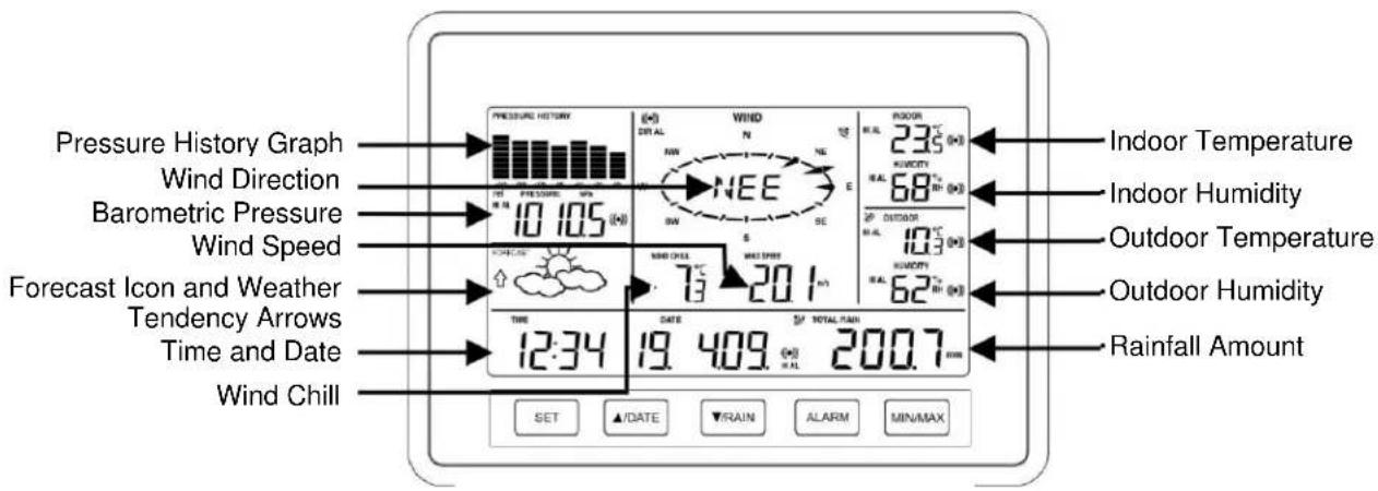
- Press the SET key to toggle between Mode 1 and Mode 2 display:
Mode 1 display:
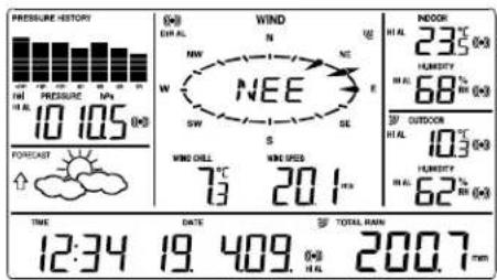
• Pressure history graph displays 24 hour history
- Outdoor temperature displayed in the outdoor section
• Wind speed displayed in the wind section
MODE 2 DISPLAY:
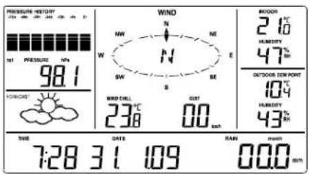
• Pressure history graph displays 72 hour history
- Dew point displayed in the outdoor section
• Wind gust displayed in the wind section
MANUAL SETTINGS
Press and hold the SET key for 3 seconds to enter the SET mode. If you wait 30 seconds without pressing any keys while in SET mode, the display will automatically return to Mode 1 display.
While in SET mode, each press of the SET key will advance to the next SET mode item.
- LCD contrast setting
- Manual time setting
- 12/24 hour time display
- Calendar setting
- °F/°C temperature unit setting
- Wind speed unit
- Rainfall unit setting
- Air pressure unit setting
- Relative pressure reference value setting
- Weather tendency threshold value
- Storm warning threshold value
- Storm alarm On/ Off setting
- Wind direction display type
- Factory Reset
LCD CONTRAST SETTING
The LCD contrast can be set within 8 levels, from "Lcd 1" to "Lcd 8" (default setting is "Lcd 5"):
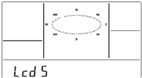
- Press and hold the SET key for 3 seconds, the contrast level digit will start flashing.
- Press the ▲UP ARROW key or ▼DOWN ARROW key to adjust the level of contrast.
- Press the SET key to confirm and to enter the MANUAL TIME SETTING.
MANUAL TIME SETTING
The time will be updated automatically with the time from the computer when the display is synchronized with the USB transceiver and connected to the Heavy Weather Pro software. The time can also be set manually by following the steps below:

-
The hour digit is flashing.
-
Press the ▲UP ARROW key or ▼DOWN ARROW key to set the hour. Continually holding the key will increase the digit faster.
- Press the SET key to switch to the minutes. The minute digit will start flashing.
- Press the ▲UP ARROW key or ▼DOWN ARROW key to set the minute. Continually holding the key will increase the digit faster.
- Press the SET key to confirm and to enter the 12/24 HOUR TIME DISPLAY SETTING.
12/24 HOUR TIME DISPLAY SETTING
The time can be set to view as 12-hour or 24-hour format. The default time-display mode is 24-h. To set to 12-h time display:
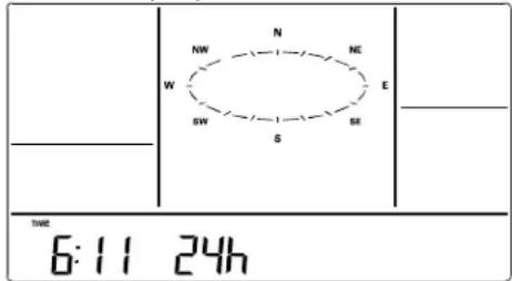
- The 24h or 12h digit is flashing
- Press the ▲UP ARROW key or ▼DOWN ARROW key to toggle the value.
- Press the SET key to confirm and to enter the CALENDAR SETTING.
Remarque:
• 24h time display format will show: Day/ Month/ Year
• 12h time display format will show: Month/ Day/ Year
CALENDAR SETTING
The default date is 1. 1. of year 2009. The date will be updated automatically with the date from the computer when the display is synchronized with the USB transceiver and connected to the Heavy Weather Pro software. The date can also be set manually by following the steps below.
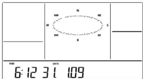
- The year digit starts flashing.
-
Press the ▲UP ARROW key or ▼DOWN ARROW key to set the year. The range runs from "00" (2000) to "99" (2099). Hold the key in to change the value faster.
-
Press the SET key to confirm the year and enter the month setting. The month digit will start flashing.
- Press the ▲UP ARROW key or ▼DOWN ARROW key to set the month. Hold the key in to change the value faster..
- Press the SET key to confirm the month and enter the date setting mode. The day digit will start flashing.
- Press the ▲UP ARROW key or ▼DOWN ARROW key to set the day. Hold the key in to change the value faster..
- Press the SET key to confirm and to enter the °F/°C TEMPERATURE UNIT SETTING.
°F/°C TEMPERATURE UNIT SETTING
The temperature can be displayed in °C or °F. (default °C).
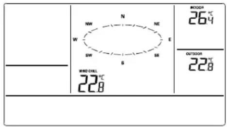
- The temperature unit is flashing
- Press the ▲UP ARROW key or ▼DOWN ARROW key to toggle between “°F” or “°C”.
- Press the SET key to confirm and to enter the WIND SPEED UNIT SETTING.
WIND SPEED UNIT SETTING
The wind speed unit can be set as mph (mile per hour), km/h (kilometer per hour), knots, Bft (Beaufort scale), or m/s (meter per second). The default unit is km/h.
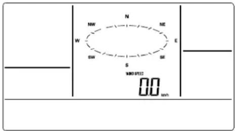
- The wind speed unit is flashing.
- Press the ▲UP ARROW key or ▼DOWN ARROW key to toggle between the unit "mph", "km/h", "bft", "knots" or "m/s".
- Press the SET key to confirm and to enter the RAINFALL UNIT SETTING.
RAINFALL UNIT SETTING
The rainfall unit can be set as inch or mm. The default unit is mm.
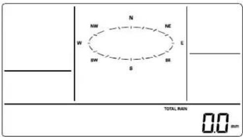
-
The rainfall unit is flashing.
-
Press the ▲UP ARROW key or ▼DOWN ARROW key to toggle between the unit "inch" or "mm"
-
Press the SET key to confirm and to enter the RELATIVE AIR PRESSURE UNIT SETTING
RELATIVE AIR PRESSURE UNIT SETTING
The relative air pressure can be set as inHg or hPa. The default unit is hPa.
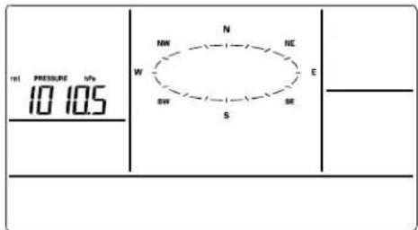
• The relative air pressure unit is flashing.
- Press the ▲UP ARROW key or ▼DOWN ARROW key to toggle between the unit "inHg" or "hPa"
- Press the SET key to confirm and to enter the RELATIVE PRESSURE REFERENCE VALUE SETTING.
RELATIVE PRESSURE REFERENCE VALUE SETTING
Note: The default reference pressure-value of the barometer is 1013 hPa when batteries are first inserted. For an exact measurement, it is necessary to first adjust the barometer to your local relative air pressure (related to elevation above sea level). Ask for the current atmospheric pressure of your home area (Local weather service, the world wide web, optician, calibrated instruments in public buildings, airport).
Note: This feature is useful for those who live at elevations above sea level, but want their air pressure display to be based on sea level elevation.
The relative air pressure can be manually set to another value within the range of 920 to 1080 hPa (27.10 to 31.90 inHg) for a better reference.
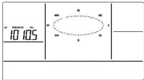
• The current relative pressure value will start flashing
- Press the ▲UP ARROW key or ▼DOWN ARROW key to increase or decrease the value. Continually holding the key will allow the value to increase faster.
- Press the SET key to confirm and to enter the WEATHER TENDENCY SENSITIVITY VALUE SETTING.
WEATHER TENDENCY SENSITIVITY LEVEL SETTING
Set the switching sensitivity value, 2,3 or 4 hPa (.06, .09, or .12 inHg) for the change in the display of weather icons. This represents the "sensitivity" of the weather forecast (the smaller the value selected, the more sensitive the weather forecast). The default value is 3 hPa. Select lower numbers for high humidity areas, i.e. Oceanside. Select high numbers for arid areas, i.e. desert.
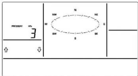
• The sensitivity value and tendency arrow will start flashing
- Press the ▲UP ARROW key or ▼DOWN ARROW key to select the value.
- Press the SET key to confirm and to enter the STORM WARNING SENSITIVITY SETTING.
STORM WARNING THRESHOLD VALUE SETTING
Define a switching sensitivity value for the Storm warning display at a decrease of air pressure from 3hPa to 9hPa (.09 inHg to .27 inHg) over 6 hours. (Default 5 hPa).
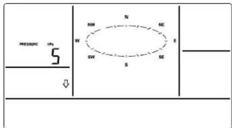
- The sensitivity value and tendency arrows will start flashing.
- Press the ▲UP ARROW key or ▼DOWN ARROW key to select the value.
- Press the SET key to confirm and to enter the STORM ALARM ON/OFF SETTING.
STORM ALARM ON/OFF SETTING
Switch the Storm Warning Alarm On or Off (Default OFF).
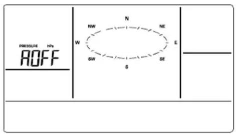
- The digit "AOFF" will start flashing.
- Press the ▲UP ARROW key or ▼DOWN ARROW key to switch On or Off the alarm. ("AOFF" = Off; "AON" = On)
- Press the SET key to confirm and to enter the WIND DIRECTION DISPLAY TYPE SETTING.

Note: If a storm warning alarm is activated, the downward weather tendency arrow will be flashing. (See WEATHER TENDENCY INDICATOR below).
WIND DIRECTION DISPLAY TYPE SETTING
The wind direction can be displayed using either compass directions or degree measurements (default setting is compass directions).
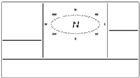
- The wind direction will start flashing.
- Press the ▲UP ARROW key or ▼DOWN ARROW key to toggle from compass directions to degree measurements.
- If you do not wish to reset the display to factory defaults, simply press the ALARM or MIN/MAX key, or wait until the SET mode times out and returns to the normal display mode.
- If you wish to perform a FACTORY RESET, press the SET key to confirm and to enter the FACTORY RESET PROCEDURE. SEE WARNINGS in the FACTORY RESET section.
FACTORY RESET PROCEDURE

WARNING:
Performing a factory reset will erase all MIN/MAX values and weather data stored in the display's internal memory and return the weather units settings back to the factory defaults. If you have not yet uploaded the data to the Heavy Weather Pro software, the data will be lost.
If you do not wish to reset the display to factory defaults either:
- press the MIN/MAX key or the ALARM key, or
- simply wait until the SET mode times out and returns to the Mode 1 display (normal mode).
To reset the display to factory defaults, follow the procedure below:

WARNING:
A factory reset will erase the connection between the display and the thermohygro sensor and require the connection to be re-established.
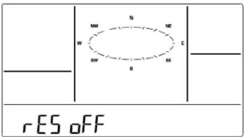
- "rES oFF" will start flashing.
- Use the ▲UP ARROW key to turn "rES on".
- Press the SET key to confirm and a countdown timer will begin counting down from "127" When the timer displays "dOnE", you must remove the batteries from the display for 10 minutes. While the batteries are out of the display, also remove the batteries from the thermo-hygro sensor.
- After waiting for 10 minutes, insert the batteries into the thermo-hygro sensor, making sure to align the "+" symbol on the batteries with the markings on the battery cover and inside the battery compartment.
- Within 2 minutes of inserting the batteries into the thermo-hygro sensor, insert the batteries into the display, making sure to align the "+" symbol on the batteries with the markings inside the battery compartment.
- Wait 5 minutes for the outdoor weather data to display. If any of the outdoor data displays "--" after waiting for 5 minutes, follow the "Setting Up" Procedure near the beginning of this manual included with the product.
TO EXIT THE MANUAL SETTING MODE
To exit the manual setting anytime during the manual setting modes, either:
- Press the ALARM key or the MIN/MAX key or
- Simply wait 30 seconds until the SET mode time out and return to the Mode 1 display (normal mode).
WEATHER ALARM OPERATIONS
The Weather alarms can be set when certain weather conditions are met according to your requirements. For example, you can set the thresholds for the outdoor temperature to +40^ (high) and -10^ (low), while enabling the high alarm and disabling the low alarm (i.e. temperatures <-10^ won't trigger alarm, but temperatures >+40^ will).
- If the value meets the condition for high alarm or low alarm, the buzzer will ring for 2 minutes and the value will blink, along with the corresponding icon ("HI AL"/ "LO AL").
- Press any key to stop a ringing alarm.
- The high and low alarms can be switched On/Off independently, according to your needs.
- If at any time during the alarm setting process you would like to exit alarm setting mode, press the MIN/MAX key or wait for about 30 seconds and the display will return to normal display mode automatically.
- In normal display mode, press the ALARM key to enter ALARM mode. Subsequent presses of the ALARM key will advance to the next weather alarm section.

Note: Weather alarms can also be set from the Heavy Weather Pro software.
Consult the Heavy Weather Pro User's Guide for instructions.
THE FOLLOWING WEATHER ALARMS CAN BE ADJUSTED IN ALARM SETTING MODE
• High and Low pressure alarms
• High and Low indoor temperature alarms
• High and Low indoor humidity alarms
• High and Low outdoor temperature alarms
• High and Low outdoor humidity alarms
• High wind gust alarm
• Wind direction alarm
• High rainfall amount in 24 hour period alarm
DEFAULT WEATHER ALARM VALUES
| Pressure | Low | 960 hPa |
| High | 1040 hPa | |
| Temperature (In or Out) | Low | 0°C |
| High | 40°C | |
| Relative Humidity (In or Out) | Low | 45% |
| High | 70% |
| Wind gust | High | 100 km/h |
| Rainfall in 24 hours | High | 50 mm |
PRESSURE ALARMS
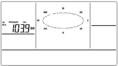
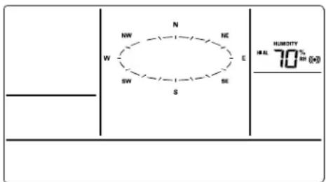
- In the normal display mode, press the ALARM key once. The high pressure alarm display will be shown.
- Press and hold the SET key for about 2 seconds. The pressure digit will start flashing.
- Press the ▲UP ARROW key or ▼DOWN ARROW key to set the high pressure alarm value. Hold the arrow key in to change the value faster.
- Press the ALARM key to confirm the setting. The digit will stop flashing.
- Press the SET key to switch the alarm on or off. The ((•))) icon indicates the alarm is switched on.
- Press the ALARM key once. The Low Pressure alarm display will be shown.
- Press and hold the SET key for about 2 seconds. The pressure digit will start flashing.
- Press the ▲UP ARROW key or ▼DOWN ARROW key to set the low pressure alarm value. Hold the arrow key in to change the value faster.
- Press the ALARM key to confirm the setting. The digit will stop flashing.
- Press the SET key to switch the alarm on or off. The ((•))) icon indicates the alarm is switched on.
- Press the ALARM key to move to the indoor temperature alarm settings.
INDOOR TEMPERATURE ALARMS
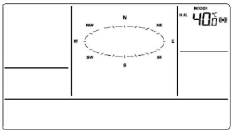
- The high indoor temperature alarm display will be shown.
- Press and hold the SET key for about 2 seconds. The temperature digit will start flashing.
-
Press the ▲UP ARROW key or ▼DOWN ARROW key to set the high indoor temperature alarm value. Hold the key in to change the value faster.
-
Press the ALARM key to confirm the setting. The digit will stop flashing.
- Press the SET key to switch the alarm on or off. The (((•))) icon indicates that the alarm is switched on.
- Press the ALARM key once. The low indoor temperature alarm display will be shown.
- Press and hold the SET key for about 2 seconds. The temperature digit will start flashing.
- Press the ▲UP ARROW key or ▼DOWN ARROW key to set the low indoor temperature alarm value. Hold the arrow key in to change the value faster.
- Press the ALARM key to confirm the setting. The digit will stop flashing.
- Press the SET key to switch the alarm on or off. The (((•))) icon indicates the alarm is switched on.
- Press the ALARM key to move to the indoor humidity alarm settings.
INDOOR HUMIDITY ALARMS
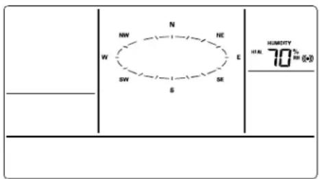
- The high indoor humidity alarm display will be shown.
- Press and hold the SET key for about 2 seconds. The humidity digit will start flashing.
- Press the ▲UP ARROW key or ▼DOWN ARROW key to set the high indoor humidity alarm value. Hold the key in to change the value faster.
- Press the ALARM key to confirm the setting. The digit will stop flashing.
- Press the SET key to switch the alarm on or off. The ((•))) icon indicates the alarm is switched on.
- Press the ALARM key once. The low indoor humidity alarm display will be shown.
- Press and hold the SET key for about 2 seconds. The humidity digit will start flashing.
- Press the ▲UP ARROW key or ▼DOWN ARROW key to set the low indoor humidity alarm value. Hold the key in to change the value faster.
- Press the ALARM key to confirm the setting. The digit will stop flashing.
- Press the SET key to switch the alarm on or off. The (((•))) icon indicates the alarm is switched on.
- Press the ALARM key to move to the outdoor temperature alarm settings.
OUTDOOR TEMPERATURE ALARMS
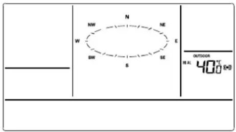
- The high outdoor temperature alarm display will be shown.
- Press and hold the SET key for about 2 seconds. The temperature digit will start flashing.
- Press the ▲UP ARROW key or ▼DOWN ARROW key to set the high outdoor temperature alarm value. Hold the key in to change the value faster.
- Press the ALARM key to confirm the setting. The digit will stop flashing.
- Press the SET key to switch the alarm on or off. The (((•))) icon indicates that the alarm is switched on.
- Press the ALARM key once. The low outdoor temperature alarm display will be shown.
- Press and hold the SET key for about 2 seconds. The temperature digit will start flashing.
- Press the ▲UP ARROW key or ▼DOWN ARROW key to set the low outdoor temperature alarm value. Hold the arrow key in to change the value faster.
- Press the ALARM key to confirm the setting. The digit will stop flashing.
- Press the SET key to switch the alarm on or off. The ((•))) icon indicates the alarm is switched on.
- Press the ALARM key to move to the outdoor humidity alarm settings.
OUTDOOR HUMIDITY ALARMS
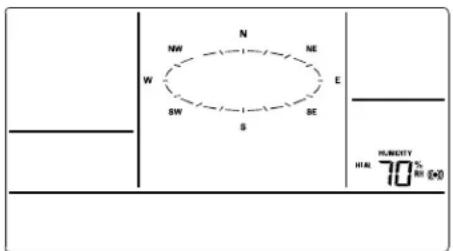
- The high outdoor humidity alarm display will be shown.
- Press and hold the SET key for about 2 seconds. The humidity digit will start flashing.
- Press the ▲UP ARROW key or ▼DOWN ARROW key to set the high outdoor humidity alarm value. Hold the key in to change the value faster.
- Press the ALARM key to confirm the setting. The digit will stop flashing.
-
Press the SET key to switch the alarm on or off. The (((•))) icon indicates the alarm is switched on.
-
Press the ALARM key once. The low outdoor humidity alarm display will be shown.
- Press and hold the SET key for about 2 seconds. The humidity digit will start flashing.
- Press the ▲UP ARROW key or ▼DOWN ARROW key to set the low outdoor humidity alarm value. Hold the key in to change the value faster.
- Press the ALARM key to confirm the setting. The digit will stop flashing.
- Press the SET key to switch the alarm on or off. The ((•))) icon indicates the alarm is switched on.
- Press the ALARM key to move to the wind gust alarm settings.
WIND GUST ALARM
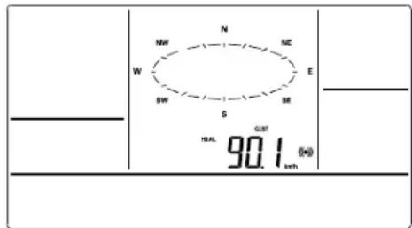
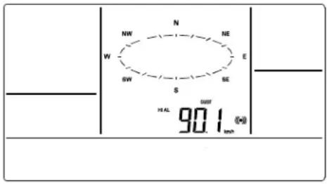
- The wind gust alarm display will be shown.
- Press and hold the SET key for about 2 seconds. The wind gust digit will start flashing.
- Press the ▲UP ARROW key or ▼DOWN ARROW key to set the wind gust alarm value. Hold the key in to change the value faster.
- Press the ALARM key to confirm the setting. The digit will stop flashing.
- Press the SET key to switch on or off the alarm. The ((•))) icon indicates the alarm is switched on.
- Press the ALARM key to move to the wind direction alarm settings.
WIND DIRECTION ALARM

Note: Multiple wind direction alarms can be set simultaneously if desired.
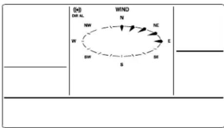
- The wind direction alarm display will be shown.
- Press and hold the SET key for about 2 seconds. The wind direction arrow on the outside of the compass circle will start flashing with the corresponding compass direction or degrees reading displayed in the center of the compass.
- Press the ▲UP ARROW key or ▼DOWN ARROW key to move the wind direction alarm pointer.
- Press the SET key to set a wind direction alarm. A pointer icon will appear inside of the compass circle to indicate an alarm setting for that wind direction.
- To remove an alarm setting for a wind direction, press the SET key again to remove the selected wind direction alarm. The arrow icon inside the compass circle will disappear.
- If more than one wind direction is desired as an alarm setting, Press the ▲UP ARROW key or ▼DOWN ARROW key to move the wind direction alarm pointer to the next desired setting.
- Press the SET key to confirm the next wind direction. A pointer icon will appear inside of the compass circle to indicate an alarm setting for that wind direction. You can set as many wind direction alarms as you desire.
- Press the ALARM key to confirm the setting. The wind direction arrow will stop flashing.
- Press the SET key to switch on or off the alarm. The ((•))) icon indicates the alarm is switched on.
- Press the ALARM key to move to the 24h rainfall alarm settings.
24H RAINFALL ALARM
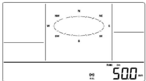
- The 24h rainfall alarm display will be shown.
- Press and hold the SET key for about 2 seconds. The 24h rainfall digit will start flashing.
- Press the ▲UP ARROW key or ▼DOWN ARROW key to set the 24h rainfall value. Hold the key in to change the value faster.
- Press the ALARM key to confirm the setting. The digit will stop flashing.
- Press the SET key to switch on or off the alarm. The (((•))) icon indicates the alarm is switched on.
- Press the ALARM key to exit the alarm settings.
HYSTERESIS
To compensate for fluctuation of the measured data, which may cause the weather
alarm to sound constantly if the measured reading is close to your set level, a hysteresis function has been implemented for each weather alarm. For example, if the high temperature alarm is set to +25°C and the current value moves to +25°C, the alarm will be activated (if it has been enabled).
| Weather data | Hysteresis |
| Temperature | 1°C |
| Humidity | 3% RH |
| Pressure | 1 hPa |
| Wind speed | 10 km/h |
Now when the temperature drops to +24.88°C or below and thereafter again increases to beyond +25°C, the data will be blinking, but no alarm will be activated. It has to drop to below +24°C (with a pre-set hysteresis of 1°C) so that the alarm can be produced again. Hysteresis values for the various weather data types are given in the table.

Note: The temperature or humidity data will keep flashing even after a key has been pressed to stop the alarm has been switched off to indicate that the current weather condition is out of the pre-set limit(s)
WEATHER FORECAST AND WEATHER TENDENCY
WEATHER FORECASTING ICONS:
Weather forecasting icons are displayed in any of the following combinations:
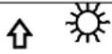 | 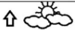 | 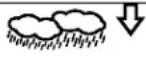 |
| Sunny | Cloudy with sunny intervals | Rainy |
For every sudden or significant change in the air pressure, the weather icons will update accordingly to represent the change in weather.
(Every time a new average pressure value has been obtained (once per minute), this value is compared with an internal reference value. If the difference between these values is bigger than the selected weather tendency sensitivity, the weather-icon changes, either for worse or for better. In this case, the current pressure value becomes the new weather tendency reference.)
If the icons do not change, either the air pressure has not changed or the change has been too small for the Weather Center to register. So you may adjust the "sensitivity" of the pressure change checking in the setting mode –see WEATHER TENDENCY SENSITIVITY VALUE SETTING above.
However, if the icon displayed is a sun or raining cloud, there will be no change of icon if the weather gets any better (with sunny icon) or worse (with rainy icon) since the icons are already at their extremes.
The icons displayed forecasts the weather in terms of getting better or worse and not necessarily sunny or rainy as each icon indicates. For example, if the current weather is cloudy and the rainy icon is displayed, it does not mean that the product is faulty because it is not raining. It simply means that the air pressure has dropped and the weather is expected to get worse but not necessarily rainy.
Note: After setting up, readings for weather forecasts should be disregarded for the next 48-60 hours. This will allow sufficient time for the Weather station to collect air pressure data at a constant altitude and therefore result in a more accurate forecast.
Common to weather forecasting, absolute accuracy cannot be guaranteed. The weather forecasting feature is estimated to have an accuracy level of about 75% due to the varying areas the Weather Center has been designed for use. In areas that experience sudden changes in weather (for example from sunny to rain), the Weather Center will be more accurate compared to use in areas where the weather is stagnant most of the time (for example mostly sunny).
If the Weather Center is moved to another location significantly higher or lower than its initial standing point (for example from the ground floor to the upper floors of a house), discard the weather forecast for the next 48-60 hours, as the Weather Center may mistake the new location as being a possible change in air-pressure when really it is due to the slight change of altitude.
WEATHER TENDENCY INDICATOR
Working together with the weather icons is the weather tendency indicators (arrow located on the left and right sides of the weather icons). When the indicator points upwards, it means that the air-pressure is increasing and the weather is expected to improve, but when indicator points downwards, the air-pressure is dropping and the weather is expected to become worse.
Taking this into account, one can see how the weather has changed and is expected to change. For example, if the indicator is pointing downwards together with cloud and sun icons, then the last noticeable change in the weather was when it was sunny (the sun icon only). Therefore, the next change in the weather will be cloud with rain icons since the indicator is pointing downwards.
Note: Once the weather tendency indicator has registered a change in air pressure, it will remain permanently visualized on the LCD.
AIR PRESSURE HISTORY (ELECTRONIC BAROMETER WITH BAROMETRIC PRESSURE TREND)
The LCD also shows the relative air pressure value and the air pressure history.
Press the SET key to toggle between Mode1 and Mode2 of the display.
- Mode 1: the bar graph displays the air pressure history of the past 24 hours in seven steps. The horizontal axis represents the last 24 hours of air pressure recording (-24, -18, -12, -9, -6, -3 and 0 hour).
- Mode 2: the bar graph displays the air pressure history of the past 72 hours in seven steps. The horizontal axis represents the last 72 hours of air pressure recording (-72, -48, -36, -24, -12, -6 and 0 hour).
The vertical bars are plotted at each of the nine steps and give the trend over the recorded period. The 0 hour vertical bar will always display at the midline height to
indicate the current air pressure. The varying height of bars inn other columns on the graph indicate a relative change in air pressure up or down from the previous measurement.
New pressure measurements are compared to previously recorded pressure measurements. The pressure change is expressed by the difference between the current ("0h") and the past readings in divisions of ±0.06 inHg or ±2 hPa. If the bars are rising from left to right, this indicates that the weather is getting better due to an increase in air pressure. If the bars are falling from left to right, this indicates that the weather is expected to get worse due to a drop in air pressure.
At every full hour, the current air pressure is used as a basis for the display of a new graph bar. The existing graph is then moved one column to the left.
Note: For accurate barometric pressure trend, the Weather Center should operate at the same altitude. For example, it should not be moved. Should the unit be moved, for instance from the ground to the second floor of the house, the readings for the next 48-60 hours shall be discarded.
Note: The bar graph will scroll right to left regularly to prevent LCD burnout.
WIND DIRECTION AND WIND SPEED MEASUREMENT
- The current wind direction is indicated by a pointer on the outer circle of the compass.
- The last 6 wind directions are displayed with pointers on the inner circle.
- The wind direction (abbreviation or degrees) is displayed in center of compass. Press the SET key to toggle between Mode1 and Mode 2 of the display
Mode 1 displays the following wind data:
• Wind direction (shown on the compass scale of 16 divisions)
• Wind chill in °C or °F
• Wind speed in km/h, mph, bft, knots or m/s
Mode 2 displays the following wind data:
• Wind direction (shown on the compass scale of 16 divisions)
- Wind chill in °C or °F
• Wind gust in km/h, mph, bft, knots or m/s
RAINFALL MEASUREMENT
The 1 hour, 24 hour, week, month or total rainfall measurement is displayed on the LCD, in the unit of mm or inch.
Press the ▼DOWN ARROW to select the rainfall display from the following modes:
- Total rainfall - reset manually (see "RESET THE MIN/MAX WEATHER DATA")
- Last 1 hour rainfall – it shows the sum of last 15 entries of four minutes rainfall
-
Last 24 hours rainfall - it shows the sum of last 24 entries of hourly rainfall
-
Last week rainfall - it shows the weekly rainfall. The rainfall measurement starts counting on the second day after power up. (Eg.: if the unit is powered up on Monday day time, then the weekly rainfall is updated every Tuesday after 23:59 h (11:59 pm))
- Last month rainfall - reset every 1^st of month at 00:00 (midnight) (12:00am).
VIEWING THE MIN/MAX WEATHER DATA
The weather station will record the maximum and minimum value of the various weather data with time and date of recording automatically. The following stored maximum and minimum weather data can be viewed by pressing the MIN/MAX key in normal display mode.
• MIN/MAX indoor temperature with the date and time of recording
- MIN/MAX indoor humidity with the date and time of recording
• MIN/MAX outdoor temperature with the date and time of recording
- MIN/MAX dew point temperature with the date and time of recording
• MIN/MAX outdoor humidity with the date and time of recording
• MAX wind gust with the date and time of recording
• Total rainfall with the date and time of recording
RESET THE MINIMUM AND MAXIMUM WEATHER DATA
To reset the aforementioned MIN/MAX weather data, you need to reset each of the data independently.
- Press MIN/MAX key to show the desired weather data.
- Press ▲UP ARROW key. The stored value will be reset to the current value and current time.
TOTAL RAINFALL AMOUNT
The total rainfall measurement is displayed in the unit of mm or inch. It shows the total rainfall accumulated since last reset of the total rainfall amount.
In either Mode 1 or Mode 2 display, press the MIN/MAX key until the display shows the total rainfall value.
To reset the rainfall reading, press the ▲UP ARROW key. The total rainfall amount will be reset to 0, and the time updated to current time.

Note: Until the first rainfall total reset is performed, the time and date of the total rainfall are displayed as "----". After the rainfall total is reset, the rainfall total display will indicate the date and time of the last rainfall total reset.
CARE AND MAINTENANCE:
- Extreme temperatures, vibration and shock should be avoided as these may cause damage to the unit and give inaccurate forecasts and readings.
- Precautions shall be taken when handling the batteries. Injuries, burns, or property damage may be resulted if the batteries are in contact with conducting materials,
heat, corrosive materials or explosives. The batteries shall be taken out from the unit before the product is to be stored for a long period of time.
- Immediately remove all low powered batteries to avoid leakage and damage. Replace only with new batteries of the recommended type.
- When cleaning the display and casings, use a soft damp cloth only. Do not use solvents or scouring agents as they may mark the LCD and casings.
- Do not submerge the unit in water.
- Special care shall be taken when handling a damaged LCD display. The liquid crystals can be harmful to user's health.
- Do not make any repair attempts to the unit. Return them to their original point of purchase for repair by a qualified engineer. Opening and tampering with the unit may invalidate their guarantee.
- Never touch the exposed electronic circuit of the device as there is a danger of electric shock should it become exposed.
- Do not expose the units to extreme and sudden temperature changes, this may lead to rapid changes in forecasts and readings and thereby reduce their accuracy.
DECLARATION OF CONFORMITY:
Hereby, Technotrade declares that this product WS 2816 is in compliance with the essential requirements and other relevant provisions of Directive 2014/53/EU and ROHS 2011/65/EC. The original EU declaration of conformity may be found at: www.technoline.de/doc/4029665028163
SPECIFICATIONS:
Indoor Temperature
-40°C to +59.9°C with 0.1°C resolution
-40°F to +139.8°F with 0.2°F resolution
("OF.L" displayed if outside this range)
OUTDOOR TEMPERATURE / DEW POINT
-40°C to +59.9°C with 0.1°C resolution
-40°F to +139.8°F with 0.2°F resolution
("OF.L" displayed if outside this range)
INDOOR HUMIDITY
1% to 99% with 1% resolution
(- - "displayed if < 1%, "99" displayed if ≥ 99%)
OUTDOOR HUMIDITY
1% to 99% with 1% resolution
("--" displayed if < 1%, "99" displayed if ≥ 99%)
WIND SPEED/ GUST
0 to 180 km/h with resolution of 0.36 km/h
0 to 111.8 mph with resolution of 0.22 mph
0 to 12 bft
0 to 97.1 knots with resolution of 0.19 knots
0 to 50 m/s with resolution of 0.1 m/s
(displays "OF.L" when > 180 km/h; 111.8 mph; 50 m/s; 12 bft; 97.1 knots)
WIND CHILL/ DEW POINT
-40°C to +59.9°C (-40°F to +140°F)
(displays "OF.L" if outside this)
Relative pressure pre-set range:
920 to 1080 hPa
27.10 to 31.90 inHg
RAINFALL (24H, TOTAL)
0 to 9999.9 mm (0" to 393.7")
(displayed "OF.L" when > 999.9mm)
OUTDOOR DATA RECEPTION
Temperature and humidity data every 13 seconds
Wind data every 17seconds
Rain data every 19 seconds
AIR PRESSURE
Relative pressure pre-set range:
920 to 1080 hpa
27.10 to 31.90 inHg
measured every 15 seconds
TRANSMISSION RANGE
Thermo-hygro: about 100 meters (330 feet) in open space
Rain: about 50 meters (164 feet) in open space
Wind: about 50 meters (164 feet) in open space
Transmission frequency: 868 MHz
Maximum transmission power USB: -18.88 dBm
Maximum transmission power TX58N: -9.12 dBm
Maximum transmission power TX59N: -3.52 dBm
Maximum transmission power TX63N: -3.13 dBm
POWER CONSUMPTION
Weather Center: 3 x C, IEC LR14, 1.5V
Thermo-hygro transmitter: 2 x C, IEC LR14, 1.5V
Rain sensor: 2 x AA LR6
Wind sensor: Solar-powered by solar cells
Battery life: approximately 24 months (Alkaline batteries recommended) for
Weather station, Thermo-hygro and Rain sensor
DIMENSIONS (L X W X H)
Weather Center: 222.0 x 42.0 x 173.0mm
Thermo-hygro transmitter: 79.4 x 89.8 x 189.3 mm
Wind sensor: 250 x 145.9 x 282.2mm
Rain sensor: ∅ 131.6 x 182.7mm
USB transceiver: 81.8 x 9 x 22.7mm
LIABILITY DISCLAIMER
- The electrical and electronic wastes contain hazardous substances. Disposal of electronic waste in wild country and/or in unauthorized grounds strongly damages the environment.
- Please contact your local or/and regional authorities to retrieve the addresses of legal dumping grounds with selective collection.
- All electronic instruments must from now on be recycled. User shall take an active part in the reuse, recycling and recovery of the electrical and electronic waste.
- The unrestricted disposal of electronic waste may do harm on public health and the quality of environment.
- As stated on the gift box and labeled on the product, reading the “User manual” is highly recommended for the benefit of the user. This product should not be thrown in general rubbish collection points.
- The manufacturer and supplier cannot accept any responsibility for any incorrect readings and any consequences that occur should an inaccurate reading take place.
- This product is designed for use in the home only as indication of the temperature.
- This product is not to be used for medical purposes or for public information.
- The specifications of this product may change without prior notice.
- This product is not a toy. Keep out of the reach of children.
- No part of this manual may be reproduced without written authorization of the manufacturer.

SAFETY INFORMATION
Precautions
- This main unit is intended to be used only indoors and the sensors are intended to be used only outdoors.
- Do not subject the unit to excessive force or shock.
- Do not expose the unit to extreme temperatures, direct sunlight, dust or humidity.
- Do not immerse in water.
- Avoid contact with any corrosive materials.
- Do not dispose this unit in a fire as it may explode.
- Do not open the inner back case or tamper with any components of this unit.
Batteries safety warnings
- Use only alkaline batteries, not rechargeable batteries.
• Install batteries correctly by matching the polarities (+/-).
• Always replace a complete set of batteries. - Never mix used and new batteries.
- Remove exhausted batteries immediately.
- Remove batteries when not in use.
- Do not recharge and do not dispose of batteries in fire as the batteries may explode.
- Ensure batteries are stored away from metal objects as contact may cause a short circuit.
- Avoid exposing batteries to extreme temperature or humidity or direct sunlight.
- Keep all batteries out of reach from children. They are a choking hazard.
Use the product only for its intended purpose!
Consideration of duty according to the battery law

Old batteries do not belong to domestic waste because they could cause damages of health and environment. You can return used batteries free of charge to your dealer and collection points. As end-user you are committed by law to bring back needed batteries to tutors and other collecting points!
Consideration of duty according to the law of electrical devices
This symbol means that you must dispose of electrical devices separated from the General household waste when it reaches the end of its useful life. Take your unit to your local waste collection point or recycling centre. This applies to all countries of the European Union, and to other European countries with a separate waste collection system.
WS 2816
DIMENSIONS (L X P X H) 101
AVIS DE NON-RESPONSABILITE 102
INFORMATIONS DE SÉCURITÉ 102
INTRODUCTION
natural_image
Line drawing of a missile or rocket with two wheels and a tapered body (no text or symbols)natural_image
Three technical line drawings: a rectangular block, a simple architectural cross-section, and a circular diagram with internal components (no text or symbols)natural_image
Diagram of a propeller with four blades and a central hub, showing no text or symbolsCAPTEUR THERMO HYGRO
PRECIPITATIONS (24 H, TOTAL)
DIMENSIONS (L X P X H)
DIMENSIONES (L X A X A) 137
natural_image
Line drawing of a missile launcher system with two wheels and a rocket (no text or labels)natural_image
Technical line drawings of mechanical components including a rectangular block, a multi-blocked housing, and a circular dial with internal components (no text or symbols)natural_image
Diagram of a propeller with four blades and a central hub, showing no text or symbolsDIMENSIONES (L X A X A)
Centro meteorológico: 222,0 x 42,0 x 173,0mm
Transmisor higrotérmico 79,4 x 89,8 x 189,3 mm
Sensor de viento: 250 x 145,9 x 282,2mm
DRAADLOZE DISPLAY 143
THERMO-/HYGROSENSOR 143
WINDSENSOR 143
REGENSENSOR 144
INSTELLING: 144
AANVULLENDE OPMERKINGEN VOOR DE MODI VAN DE
ZONNEWINDSENSOR: 145
DE SENSOREN MONTEREN EN DE DRAADLOZE DISPLAY PLAATSEN: 146
WINDSENSOR 147
REGENSENSOR 147
THERMO-/HYGROSENSOR 147
HEAVY WEATHER PC-SOFTWARE 148
FUNCTIETOETSEN: 148
TOETS ▲/DATE 148
TOETS ▼/RAIN 148
ALARM-TOETS 148
MIN/MAX-TOETS 149
LCD-SCHERM 149
DISPLAYMODUS 1: 149
DISPLAYMODUS 2: 150
HANDMATIGE INSTELLINGEN 150
LCD-CONTRASTINSTELLING 150
HANDMATIGE TIJDINSTELLING 151
INSTELLING 12/24 UUR TIJDWEERGAVE 151
KALENDERINSTELLING 152
INSTELLING TEMPERATUUREENHEID °F/°C 152
EENHEIDINSTELLING WINDSNELHEID 153
INSTELLING NEERSLAGEENHEID 153
INSTELLING RELATIEVE LUCHTDRUKEENHEID 154
INSTELLING REFERENTIEWAARDE RELATIEVE DRUK 154
INSTELLING GEVOELIGHEIDSNIVEAU WEERTENDENS 155
INSTELLING DREMPELWAARDE STORMWAARSCHUWING 155
INSTELLING STORMALARM AAN/UIT 156
INSTELLING WEERGAVETYPE WEERTENDENS 156
RESETPROCEDURE FABRIEKSWAARDEN 157
DE HANDMATIGE INSTELLINGSMODUS VERLATEN 158
HET WEERALARM GEBRUIKEN 158
DE VOLGENDE WEERALARMEN KUNNEN WORDEN INGESTELD IN DE
ALARMINSTELLINGSMODUS 158
STANDAARD WAARDEN VOOR DE WEERALARMEN 159
DRUKALARMEN 159
ALARMEN VOOR BINNENTEMPERATUUR 160
ALARMEN VOOR BINNENVOCHTIGHEID 160
ALARMEN VOOR BUITENTEMPERATUUR 161
ALARMEN VOOR BUITENVOCHTIGHEID 162
ALARM VOOR WINDSTOTEN 163
ALARM VOOR WINDRICHTING 163
ALARM 24U NEERSLAG 164
HYSTERESIS 165
WEERSVERWACHTING EN WEERTENDENS 165
PICTOGRAMMEN VOOR WEERSVERWACHTING: 165
INDICATOR WEERTENDENS 166
LUCHTDRUKGESCHIEDENIS (ELEKTRONISCHE BAROMETER MET
BAROMETRISCHE DRUKTREND) 166
METING VAN WINDRICHTING EN WINDSNELHEID 167
NEERSLAGMETING 168
DE MIN/MAX WEERGEGEVENS CONTROLEREN 168
DE MINIMALE EN MAXIMALE WEERGEGEVENS RESETTEN 168
TOTALE HOEVEELHEID NEERSLAG 169
ONDERHOUD EN REINIGING: 169
VERKLARING VAN OVEREENSTEMMING: 170
SPECIFICATIES: 170
BINNENTEMPERATUUR 170
BUITENTEMPERATUUR/DAUWPUNT 170
BINNENVOCHTIGHEID 170
natural_image
Line drawing of a missile launcher system with two wheels and an external missile (no text or symbols)natural_image
Pure technical line drawings of mechanical components without any text or symbolsnatural_image
Diagram of a four-bladed propeller with a downward arrow indicating compression or disassembly (no text or symbols)Regensensor: 2 x AA LR6
Weerstation: 222,0 x 42,0 x 173,0mm
Thermo-/hygrozender: 79,4 x 89,8 x 189,3 mm
Windsensor: 250 x 145,9 x 282,2mm
Regensensor: ∅ 131,6 x 182,7mm
USB-zendontvanger: 81,8 x 9 x 22,7mm
AANSPRAKELIJKHEID DISCLAIMER
DIMENSIONI (L X P X A) 206
ESCLUSIONE DI RESPONSABILITÀ 207
natural_image
Technical line drawing of a mechanical device with no visible text or symbolsnatural_image
Technical line drawing of a mechanical component with top, front, and side views (no text or symbols)natural_image
Diagram of a propeller blade assembly with a downward arrow indicating compression or disassembly (no text or symbols present)ALLARME UMIDITÀ INTERNA
QUANTITÀ DI PIOGGIA TOTALE
DIMENSIONI (L X P X A)
Stazione meteorologica: 222,0 x 42,0 x 173,0mm
Sensore termoigrometrico: 79,4 x 89,8 x 189,3 mm
Anemometro: 250 x 145,9 x 282,2mm
Pluviometro: ∅ 131,6 x 182,7 mm
ESCLUSIONE DI RESPONSABILITÀ
MANUÁLNÍ NASTAVENÍ ČASU 220
NASTAVENÍ ZOBRAZENÍ ČASU 12/24 HOD. 221
NASTAVENÍ JEDNOTKY TEPLOTY °C/°F 222
NASTAVENÍ JEDNOTKY RYCHLOSTI VĚTRU 222
NASTAVENÍ JEDNOTKY SRÁŽEK 223
NASTAVENÍ JEDNOTKY RELATIVNÍHO TLAKU VZDUCHU 223
NASTAVENÍ REFERENČNÍ HODNOTY RELATIVNÍHO TLAKU 224
NASTAVENÍ ÚROVNĚ CITLIVOSTI TENDENCE POČASÍ 224
NASTAVENÍ PRAHOVÉ HODNOTY VAROVÁNÍ PŘED BOUŘKOU 225
NASTAVENÍ ZAPNUTÍ/VYPNUTÍ ALARMU BOUŘKY 225
natural_image
Line drawing of a missile or aircraft with two wheels and a tapered body (no text or symbols)natural_image
Technical line drawings of mechanical components including a rectangular block, a stepped component, and a circular housing (no text or symbols)natural_image
Diagram of a four-bladed propeller with a downward arrow indicating compression or disassembly (no text or symbols present)MANUÁLNÍ NASTAVENÍ ČASU
NASTAVENÍ JEDNOTKY TEPLOTY °C/°F
VÝCHOZÍ HODNOTY ALARMU POČASÍ
CELKOVÉ MNOŽSTVÍ SRÁŽEK
Meteostanice 222,0 x 42,0 x 173,0mm
Vysílač teploty a vlhkosti: 79,4 x 89,8 x 189,3 mm
WYMIARY (D X SZ X W) 274
OGRANICZENIA ODPOWIEDZIALNOŚCI 274
INFORMACJE BEZPIECZEŃSTWA 274
WSTEP
natural_image
Line drawing of a missile or aircraft with two wheels and a tapered body (no text or symbols)natural_image
Pure technical line drawings of mechanical components without any text or symbolsnatural_image
Diagram of a propeller with arrow indicating downward motion (no text or symbols)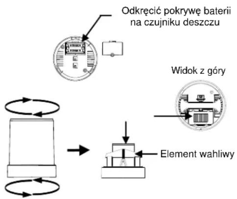
flowchart
graph TD
    A["Odkręcić pokrywę baterii na czujniku deszczu"] --> B["Object with circular arrow"]
    C["Widok z góry"] --> D["Component with circular arrow"]
    E["Element wahliwy"] --> F["Object with circular arrow"]
ALARMY WILGOTNOŚCI W POMIESZCZENIU
ALARM PODMUCHÓW WIATRU
DBANIE I KONSERWACJA:
WYMIARY (D X SZ X W)
- GRUNDEINSTELLUNG: 6
- FUNKTIONSTASTEN: 10
- Wireless Professional Weather Center
- TABLE OF CONTENTS
- FEATURES: 39
- SETTING UP: 41
- MOUNTING THE SENSORS AND PLACEMENT OF THE WIRELESS DISPLAY:
- 43
- FUNCTION KEYS: 44
- LCD SCREEN 45
- MANUAL SETTINGS: 46
- WEATHER ALARM OPERATIONS 54
- HYSTERESIS 59
- WEATHER FORECAST AND WEATHER TENDENCY 60
- AIR PRESSURE HISTORY (ELECTRONIC BAROMETER WITH BAROMETRIC
- PRESSURE TREND) 61
- WIND DIRECTION AND WIND SPEED MEASUREMENT 62
- RAINFALL MEASUREMENT 62
- VIEWING THE MIN/MAX WEATHER DATA 63
- CARE AND MAINTENANCE: 63
- DECLARATION OF CONFORMITY 64
- SPECIFICATIONS: 64
- LIABILITY DISCLAIMER AND SAFETY INFORMATION 66
- INTRODUCTION
- FEATURES:
- WIRELESS DISPLAY
- THERMO-HYGRO SENSOR
- WIND SENSOR
- RAIN SENSOR
- SETTING UP:
- ADDITIONAL NOTES FOR THE SOLAR WIND SENSOR MODES:
- IDLE MODE
- STOP MODE
- Note:
- HEAVY WEATHER PC SOFTWARE
- FUNCTION KEYS:
- SET key
- ▲/DATE key
- ▼/RAIN key
- ALARM key
- MIN/MAX key
- LCD SCREEN
- MANUAL SETTINGS
- LCD CONTRAST SETTING
- MANUAL TIME SETTING
- 12/24 HOUR TIME DISPLAY SETTING
- Remarque:
- CALENDAR SETTING
- °F/°C TEMPERATURE UNIT SETTING
- WIND SPEED UNIT SETTING
- RAINFALL UNIT SETTING
- RELATIVE AIR PRESSURE UNIT SETTING
- RELATIVE PRESSURE REFERENCE VALUE SETTING
- WEATHER TENDENCY SENSITIVITY LEVEL SETTING
- STORM WARNING THRESHOLD VALUE SETTING
- STORM ALARM ON/OFF SETTING
- WIND DIRECTION DISPLAY TYPE SETTING
- FACTORY RESET PROCEDURE
- WARNING:
- TO EXIT THE MANUAL SETTING MODE
- WEATHER ALARM OPERATIONS
- THE FOLLOWING WEATHER ALARMS CAN BE ADJUSTED IN ALARM SETTING MODE
- PRESSURE ALARMS
- INDOOR TEMPERATURE ALARMS
- INDOOR HUMIDITY ALARMS
- OUTDOOR TEMPERATURE ALARMS
- OUTDOOR HUMIDITY ALARMS
- WIND GUST ALARM
- WIND DIRECTION ALARM
- 24H RAINFALL ALARM
- HYSTERESIS
- WEATHER FORECAST AND WEATHER TENDENCY
- WEATHER FORECASTING ICONS:
- WEATHER TENDENCY INDICATOR
- AIR PRESSURE HISTORY (ELECTRONIC BAROMETER WITH BAROMETRIC PRESSURE TREND)
- WIND DIRECTION AND WIND SPEED MEASUREMENT
- RAINFALL MEASUREMENT
- VIEWING THE MIN/MAX WEATHER DATA
- RESET THE MINIMUM AND MAXIMUM WEATHER DATA
- TOTAL RAINFALL AMOUNT
- CARE AND MAINTENANCE:
- DECLARATION OF CONFORMITY:
- SPECIFICATIONS:
- Indoor Temperature
- OUTDOOR TEMPERATURE / DEW POINT
- INDOOR HUMIDITY
- OUTDOOR HUMIDITY
- WIND SPEED/ GUST
- WIND CHILL/ DEW POINT
- RAINFALL (24H, TOTAL)
- OUTDOOR DATA RECEPTION
- AIR PRESSURE
- TRANSMISSION RANGE
- POWER CONSUMPTION
- DIMENSIONS (L X W X H)
- LIABILITY DISCLAIMER
- SAFETY INFORMATION
- Precautions
- Batteries safety warnings
- WS 2816
- CAPTEUR THERMO HYGRO
- PRECIPITATIONS (24 H, TOTAL)
- DIMENSIONS (L X P X H)
- DIMENSIONES (L X A X A)
- INSTELLING: 144
- AANVULLENDE OPMERKINGEN VOOR DE MODI VAN DE
- ZONNEWINDSENSOR: 145
- DE SENSOREN MONTEREN EN DE DRAADLOZE DISPLAY PLAATSEN: 146
- FUNCTIETOETSEN: 148
- LCD-SCHERM 149
- HANDMATIGE INSTELLINGEN 150
- HET WEERALARM GEBRUIKEN 158
- HYSTERESIS 165
- WEERSVERWACHTING EN WEERTENDENS 165
- ONDERHOUD EN REINIGING: 169
- VERKLARING VAN OVEREENSTEMMING: 170
- SPECIFICATIES: 170
- AANSPRAKELIJKHEID DISCLAIMER
- ESCLUSIONE DI RESPONSABILITÀ 207
- ALLARME UMIDITÀ INTERNA
- QUANTITÀ DI PIOGGIA TOTALE
- DIMENSIONI (L X P X A)
- ESCLUSIONE DI RESPONSABILITÀ
- MANUÁLNÍ NASTAVENÍ ČASU
- NASTAVENÍ JEDNOTKY TEPLOTY °C/°F
- CELKOVÉ MNOŽSTVÍ SRÁŽEK
- WSTEP
- ALARMY WILGOTNOŚCI W POMIESZCZENIU
- ALARM PODMUCHÓW WIATRU
- DBANIE I KONSERWACJA:
- WYMIARY (D X SZ X W)
Brand : Techno Line
Model : WS 2816
Category : Weather Station