CDE8452T - Monitor VIEWSONIC - Free user manual and instructions
Find the device manual for free CDE8452T VIEWSONIC in PDF.

User questions about CDE8452T VIEWSONIC
0 question about this device. Answer the ones you know or ask your own.
Ask a new question about this device
Download the instructions for your Monitor in PDF format for free! Find your manual CDE8452T - VIEWSONIC and take your electronic device back in hand. On this page are published all the documents necessary for the use of your device. CDE8452T by VIEWSONIC.
USER MANUAL CDE8452T VIEWSONIC
Model No. VS16480/VS16477/VS16436/VS15420
Europe : http://www.viewsoniceurope.com/uk/support/recycling-information/
Taiwan : http://recycle.epa.gov.tw/recycle/index2.aspx
1. Démarrage
natural_image
Illustration of various electronic devices including cables, a remote control, batteries, and CD/DVD components (no text or labels)26 ESC/EXIT、D. SETUP:
natural_image
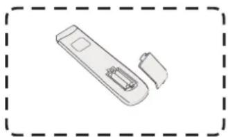
Illustration of a hand holding a smartphone with a small object inside, enclosed in a dashed border (no text or symbols)(1)
natural_image
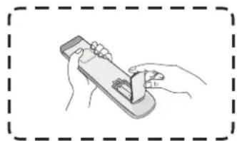
Simple line drawing of a handheld device with two ports and a handle, enclosed in a dashed border (no text or symbols)(2)
natural_image
Illustration of hands using a handheld device to interact with a small object (no text or symbols visible)(3)
text_image
30° 30° 8Mnatural_image
Simple diagram with a speaker icon, a blue horizontal line, and a gray vertical bar (no text or symbols)Réglage du volume :
text_image
Audio Screen Display Adjust 30 Volume 5 Bass 5 Treble 0 Balance Standard Movie Meeting Class Mutenatural_image
Three circular icons with various symbols (arrow, checkmark, document, pencil, magnifying glass, clipboard, brush, globe, folder) arranged in a grid, no text or labels present.text_image
ViewBoard Lite Folders Browser PIP Settings Appsnatural_image
Computer desktop with green screen and tool icons at bottom (no text or symbols on main canvas)text_image
New Open Save Save to USB Export as IMG Background Brightnesstext_image
Folders 1 Storage USB 3 All Doc Note Picture Media 2016-01-28.png 5 4 2016-01-04-20-50-28.png Extension: 100x100x Size: 100x Time: 2016.07.04natural_image
Computer window displaying a loading screen with a simple loading icon (no text or symbols on the icon itself)text_image
Ethernet checking Ethernet checking Display Storage Apps Language & Input Date & Time Startup and shutdown Floating Annotation Setting Input Setting About device Switcher: 00 MAC address: 00:25:92:E4:2E 70 IP address: 192.168.25.113 Mask: 255.255.255.0 Gate: 192.168.25.1 Advancedtext_image
Browser Folders Kingsoft Office Settings ViewBoard Lite ViewBoard Lite Folders Browser PIP Settings Home- Configuration
- Navigateur
- Dossiers
- ViewBoard Lite
Kingsoft Office
text_image
Playing Setting animation effect playing Interval Left Set Wallpapertext_image
playlist 00:00:35 00:03:45text_image
playlist 02:25:13 01:30:09natural_image
Illustration of a hand cleaning a computer monitor (no text or symbols visible)This document describes the hardware interface spec and software protocols of RS232 interface communication between ViewSonic Commercial TV / Digital Signage and PC or other control unit with RS232 protocol.
The protocol contains three sections command:
- Set-Function
- Get-Function
• Remote control pass-through mode
※ In the document below, "PC" represents all the control units that can sent or receive the RS232 protocol command.
9.2 Description
9.2.1 Hardware specification
Viewsonic TV communication port on the rear side:
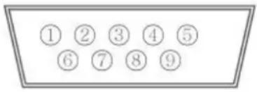
(1) Connector type: DSUB 9-Pin Male
(2) Pin Assignment
Male DSUB 9-Pin (outside view)
text_image
① ② ③ ④ ⑤ ⑥ ⑦ ⑧ ⑨| Pin # Signal Remark | ||
| 1 NC | ||
| 2 RXD Input to Commercial TV or DS | ||
| 3 TXD Output from Commercial TV or DS | ||
| 4 NC | ||
| 5 GND | ||
| 6 NC | ||
| 7 NC | ||
| 8 NC | ||
| 9 NC | ||
| frame GND | ||
* Use of crossover (null modem) cable required for use with PC
[Special case]
3.5mm barrel connector
| Pin # Signal Remark | |
| Tip TXD Output from DS | Commercial TV or DS |
| Ring RXD Input to Commercial TV or DS | |
| Sleeve GND | |
9.2.2 Communication Setting
- Baud Rate Select: 9600bps (fixed)
- Data bits: 8 bits (fixed)
- Parity: None (fixed)
- Stop Bits: 1 (fixed)
9.2.3 Command Message Reference
PC sends to Monitor command packet followed by "CR". Every time PC sends control command to the Monitor, the Monitor shall respond as follows:
- If the message is received correctly it will send “+” (02Bh) followed by “CR” (00Dh)
- If the message is received incorrectly it will send “-” (02Dh) followed by “CR” (00Dh)
9.3 Protocol
9.3.1 Set-Function Listing
The PC can control the TV/DS for specific actions. The Set-Function command allows you to control the TV/DS behavior in a remote site through the RS232 port. The Set-Function packet format consists of 9 bytes.
Set-Function description:
Length: Total Byte of Message excluding "CR".
TV/DS ID Identification for each of TV/DS (01\~98; default is 01)
ID "99" means to apply the set command for all connected displays. Under such circumstances, only ID#1 display has to reply.
The TV/DS ID can be set via the OSD menu for each TV/DS set.
Command Type Identify command type,
"s" (0x73h): Set Command
“+” (0x2Bh): Valid command Reply
“-” (0x2Dh): Invalid command Reply
Command: Function command code: One byte ASCII code.
Value[1\~3]: Three bytes ASCII that defines the value.
CR 0x0D
Set-Function format
Send: (Command Type="s")
For VT2405LED-1 and VT3205LED, the set "Power on" command is the exception.
Reply: (Command Type="+" or "-"')
- The reply for "Power on" command is the exception for VT2405LED-1 and VT3205LED. It's 0x322B0D (2+
). - When PC applies command to all displays (ID=99), only the #1 set needs to reply by the name of ID=1.
Example1: Set Brightness as 76 for TV-02 and this command is valid. Send (Hex Format)
| Name | Length ID | Command Type | Command | Value1 | Value2 | Value3 | CR |
| Hex | 0x38 | 0x30 | 0x73 | 0x24 | 0x30 | 0x37 | 0x36 |
Reply (Hex Format)
| Name | Length | ID | Command Type | CR |
| Hex | 0x34 | 0x300x32 | 0x2B | 0x0D |
Example2: Set Brightness as 176 for TV-02 and this command is NOT valid Send (Hex Format)
| Name | Length ID | Command Type | Command | Value1 | Value2 | Value3 | CR |
| Hex | 0x38 | 0x30 | 0x73 | 0x24 | 0x31 | 0x37 | 0x36 |
| 0x32 |
Reply (Hex Format)
| Name | Length ID | Command | Type | CR |
| Hex | 0x34 0x30_0x32 | 0x2D 0x0D | _ | |
Set-function table
| Set Function | Length | ID | Command Type(ASCII) Code (ASCII) | Command ValueCode (Hex) (Three ASCII bytes) | Range Comments | ||
| Power on/off(standby) | 8 s ! | 21 000 | 0: STBY | 001: ON | Exclude VT2405-1, and VT3205 | ||
| Input Select 8 | s “ 22 000 | 0: TV | 001: AV002: S-Video003: YPbPr004: HDMI014: HDMI2024: HDMI3034: HDMI4005: DVI006: VGA1016: VGA2026: VGA3007: OPS017: Embd Player008: Internalmemory009: DP | 1. No need for USB2. For the case of twomore same sources,the 2nd digital isused to indicate theextension.3. Exclude VT2405-1,and VT3205 | |||
| Contrast | 8 s | # 23 000 ~ 100 | |||||
| Brightness | 8 s | $ | 24 000 ~ 100 | ||||
| Sharpness 8 s | % | 25 000 ~ 100 | |||||
| Color 8 s | & | 26 000 ~ 100 | |||||
| Tint | 8 s | ‘ | 27 000 ~ 100 | ||||
| Color mode | 8 s ) | 29 000 | 0: Normal | 001: Warm002: Cold003: Personal | |||
| Sound | 8 s - | 2D | 000: SRS Off | 001: SRS On | (for TV) | ||
| Bass | 8 s . | 2E | 000 ~ 100 | (for TV) | |||
| Treble | 8 s / | 2F 000 | 0 ~ 100 | (for TV) | |||
| Balance | 8 | s | 0 | 30 | 000 ~ 100 | (for TV)Sets Balance position | |
| Picture Size | 8 s | 1 | 31 000: FULL | 001: NORMAL002: CUSTOM003: DYNAMIC004: REAL | (for DS) | ||
| OSD language | 8 s | 2 | 32 000: English | 001: French002: Spanish | Extend the valuefor more supportedlanguages | ||
| OSD timeout | 8 | s | 3 | 33 | 005 ~120 Sec | Set OSD timeout | |
| Power lock 8 s | 4 34 000: | Unlock | 001: Lock | |||
| Volume 8 s 5 | 35 000 ~ | 100 | 900: Volume down (-1)901: Volume up (+1) | |||
| Mute 8 s 6 36 | 000: OFF | 001: ON (mute) | ||||
| Off Timer 8 s | 7 37 000: | OFF | 001~024 (hour) | |||
| PIP-Mode 8 s | 9 39 000: | OFF | 001: PIP002: PBP | (for DS) | ||
| PIP-Sound select | 8 s : 3A 000: | Main | 001: PIP | (for DS) | ||
| PIP-Position 8 s ; 3B 000: | Up | 001: Down002: Left003: Right | (for DS) | |||
| PIP-Input 8 s < 3C 000: | TV | 001: AV002: S-Video003: YPbPr004: HDMI014: HDMI2024: HDMI3005: DVI006: PC/VGA007: OPS | (for DS)For the case of two more same sources, the 2^nd digital is used to indicate the extension. | |||
| Button lock 8 s | 8 38 000: | Unlock | 001: Lock | |||
| TV channel (DTV) | 8 s < | 3C | For -0:001~999A00~F99(1000~1599)For -k: 1^st and 2^nd char are same as -03th char is CHAR [ASC (3th digi) + k x 10] | (for TV)1. Channel OSD number but not frequency number2. For VT3255 and VT4236 only | ||
| TV channel (ATV) | 8 s = | 3D 001~999 (for TV) | ||||
| Menu lock 8 s > | 3E 000: Unlock | 001: Lock | ||||
| Number | 8 s | @ | 40 000~009 (for TV) | |||
| Key Pad | 8 s | A | 41 000: UP | 001: DOWN002: LEFT003: RIGHT004: ENTER005: INPUT006: MENU/EXIT | ||
| Remote Control | 8 s B | 42 000: Disable | 001: Enable002: Pass through | Disable: RCU has no effect on HDTV.Enabled: RCU controls the HDTV. This is the power up default on the HDTV.Pass through: RCU has no effect on HDTV and all RCU command codes are transmitted to FC via the RS232 port.See page 26 for more details | ||
| Setup wizard | 8 s C 43 000: Disable | 001: Enable | (for TV)Disable: to skip the initial setup wizard | |||
| Tiling-Mode 8 | s P 50 000: OFF | 001: ON | (for DS) | |||
| Tiling-Compensation | 8 s Q | 51 000: OFF | 001: ON | (for DS)Bezel width compensation | ||
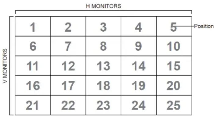
| Tiling-H by V Monitors | 8 s R | 52 01x~09x: H | 0x1~0x9: V | (for DS)1.2nddigital for H monitors2.3rddigital for V monitors | ||
| Tiling-Position | 8 s S | 53 001~025 (for DS) | Copy the screen of Position# to identified display | |||
| Restore default | 8 s ~ | 7E 000 Rests HDTV to factory | setting | |||
NOTE:
1. Behavior at lock modes
| Lock Mode | Behavior |
| Button Lock | 1. Lock all buttons on the front panel and RCU, except for “Power”.2. All the SET functions should be workable via RS32, even the ones with according hot key in RCU like Mute,...etc. |
| MENU Lock | 1. Lock “MENU’ key of front panel and RCU.2. The Factory and Hospitality modes should not be blocked for the model using MENU-combined key to enter these two modes. Alternative approach will be indicated separately if any limitation by model. |
| POWER Lock 1. | Lock “POWER” key on the front and RCU.2. The SET_POWER on/off should be workable via RS232, but does not mean the POWER lock will be released under this case.3. Can not be unlocked by reset in OSD setting.4. Will auto AC power-on in power-lock5. Under power-lock, the set will not enter power saving when no PC signal and neither not turn off when no other video signals after 15min. |
| Remote control disable | Lock the RCU keys, but keep the front panel buttons workable. |
2. Example for value setting of SET\_TV channel DTV
012-0: 0x 30 31 32
012-1: 0x 30 31 42
1012-2: 0x 41 31 52
1512-3: 0x 46 31 62
3. Tiling definition of H Monitors/ V Monitors/ and Position
heatmap
H MONITORS | Position | V MONITORS | 1 | 2 | 3 | 4 | 5 | | :--- | :--- | :--- | :--- | :--- | :--- | :--- | | 1 | 6 | 6 | 7 | 8 | 9 | 10 | | 1 | 11 | 11 | 12 | 13 | 14 | 15 | | 1 | 16 | 16 | 17 | 18 | 19 | 20 | | 1 | 21 | 21 | 22 | 23 | 24 | 25 | Position9.3.2 Get-Function Listing
The PC can interrogate the TV/DS for specific information. The Get-Function packet format consists of 9 bytes which is similar to the Set-Function packet structure. Note that the "Value" byte is always = 000
Get-Function description:
Length: Total Byte of Message excluding "CR".
TV/DS ID Identification for each of TV/DS (01\~98; default is 01).
Command Type Identify command type,
"g" (0x67h): Get Command
“r” (0x72h): Valid command Reply
“-” (0x2Dh): Invalid command Reply
Command: Function command code: One byte ASCII code.
Value[1\~3]: Three bytes ASCII that defines the value.
CR 0x0D
Get-Function format
Send: (Command Type="g")
NOTE: Get "Power STBY status" is the exception for VT2405LED-1 and VT3205LED.
Reply: (Command Type="r" or "--")
If the Command is valid, Command Type = "r"
NOTE: The reply for "Power STBY status" command is the exception for VT2405LED-1 and V3205LED. It's 0x36 72 6C 30 30 30 0D (6rl000
If the Command is Not valid, Command Type="-"
Example1: Get Brightness from TV-05 and this command is valid.
The Brightness value is 67.
Send (Hex Format)
| Name | Length ID | Command Type | Command | Value1 | Value2 | Value3 | CR |
| Hex | 0x38 0x300x35 | 0x67 0x62 | 0x30 0x30 | 0x30 0x0D____ | ____ | ____ | |
Reply (Hex Format)
| Name | Length ID | Command Type | Command | Value1 | Value2 | Value3 | CR |
| Hex | 0x38 0x30 0x35 | 0x72 0x6 | 2 0x30 0x36 | 0x37 0x0 | D____ | ____ | ____ |
Example2: Get Brightness from TV-05, but the Brightness command ID is error and it is NOT in the command table.
Send (Hex Format)
| Name | Length ID | Command Type | Command | Value1 | Value2 | Value3 | CR |
| Hex | 0x38 | 0x30 | 0x67 | 0XD3 | 0x30 | 0x30 | 0x0D |
Reply (Hex Format)
| Name | Length ID | Command Type | CR |
| Hex | 0x34 0x30_0x35 | 0x2D | 0x0D |
Get-Function table
| Get Function | Length | ID | Command Type (ASCII) Code | Command Response Range Comments | |||
| Code (ASCII) Code (Hex) (Three ASCII bytes) | |||||||
| Get-Contrast | 8 g a 61 | 000 ~ | 100 | ||||
| Get-Brightness | 8 g b | 62 000 ~ 100 | |||||
| Get-Sharpness | 8 g c | 63 000 ~ 100 | |||||
| Get-Color 8 g | d 64 000 | ~ 100 | |||||
| Get-Tint 8 g e | 65 000 ~ 100 | ||||||
| Get-Volume | 8 g | f | 66 000 ~ 100 | ||||
| Get-Mute | 8 g g | 67 000: Off | 001: On (muted) | ||||
| Get-Input select | 8 g | j | 6A 000~ See Set-function | table | |||
| Get-Power status: ON/ STBY | 8 g | l | 6C 001: ON | 000: STBY | Exclude VT2405-1, and VT3205 | ||
| Get-Remote control | 8 g n | 6E | 000: Disable | 001: Enable 002: Pass through | Gets RCU mode status | ||
| Get-Power lock | 8 g o | 6F | 000: Unlock | 001: Lock | |||
| Get-Button lock | 8 g p | 70 000: Unlock | 001: Lock | ||||
| Get-Menu lock | 8 g q | 71 000: Unlock | 001: Lock | ||||
| Get-Setup wizard | 8 g s | 73 000: Disable | 001: Enable | (for TV) | |||
| Get-PIP mode | 8 g | t | 74 000: OFF | 001: PIP 002: PBP | (for DS) | ||
| Get-PIP input | 8 g u 75 | 000 ~ | (for DS) | See Set-function table | |||
| Get-Tiling Mode | 8 g v | 76 000: OFF | 001: ON | (for DS) | |||
| Get-Tiling Compensation | 8 g | w | 77 000: OFF | 001: ON | (for DS) Bezel width compensation | ||
| Get-Tiling H by V monitors | 8 g x | 78 01x~09x: | H monitors 0x1~0x9: V monitors | (for DS) 1. 2^nd digital for H monitors 2. 3^rd digital for V monitors | |||
| Get-Tiling position | 8 g y | 79 000: OFF | 001~025 | (for DS) Copy the screen of Position# to identified display | |||
| Get-ACK | 8 g z | 7A | 000 | This command is | used to test the communication link | ||
NOTE:
- Time log data is replied as 6 sequential strings in following order.
1: Previous power-on date (month/ day)
2: Previous power-on time (hour/ min)
3: Previous power-off date (month/ day)
4: Previous power-off time (hour/ min)
5: Last power-on date (month/day)
6: Last power-on time (hour/ min)
- Time log data definition
| Value 1 Value 2 Value 3 | ||
| On/ Off indicator0: Off1: On | Month code Day code | |
| Hour code Minute code | ||
Hex code (in hex) = Original data (in dec) + 20
| Date & Time | Code (ASCII) | Code (Hex) | Date & Time | Code (ASCII) | Code (Hex) | Date & Time | Code (ASCII) | Code (Hex) | Date & Time | Code (ASCII) | Code (Hex) |
| 0 space | 20 16 6 36 | 32 R 52 | 48 h 68 | ||||||||
| 1 ! 21 17 | 7 37 33 S | 53 49 i 69 | |||||||||
| 2 “ 22 18 | 8 38 34 T | 54 50 p 70 | |||||||||
| 3 # 23 19 | 9 39 35 | J 55 51 q 71 | |||||||||
| 4 $ 24 20 | @ 40 36 | V 56 52 r 72 | |||||||||
| 5 % 25 21 | A 41 37 | W 57 53 | s 73 | ||||||||
| 6 & 26 22 | B 42 38 | X 58 54 t 74 | |||||||||
| 7 ’ 27 23 | C 43 39 Y | 59 55 u 75 | |||||||||
| 8 ( 28 24 | D 44 40 | 60 56 v 76 | |||||||||
| 9 ) 29 25 | E 45 41 a | 61 57 w 77 | |||||||||
| 10 0 30 26 | F 46 42 | b 62 58 x 78 | |||||||||
| 11 1 31 27 | G | 47 43 c | 63 59 y 79 | ||||||||
| 12 2 32 28 | H 48 44 d 64 | ||||||||||
| 13 3 33 29 | I 49 45 e 65 | ||||||||||
| 14 4 34 30 | P 50 46 f 66 | ||||||||||
| 15 5 35 31 | Q | 51 47 g | 67 |
Month: 1\~12
Day: 1\~31
Hour: 00\~23
Min: 00\~59
3. Time log data example
Assumed the power-on/off record of display#01 as below
2014-8/31 08:00 On
2014-8/31 22:00 Off
2014-9/1 10:30 On
2014-9/1 11:00 To send "GET-Time log" command
Send: 0x 38 30 31 67 31 30 30 30 0D
Reply:
1 0x 38 30 31 72 31 31 28 51 0D (On 8/31)
2 0x 38 30 31 72 31 31 28 20 0D (On 08:00)
3 0x 38 30 31 72 31 30 28 51 0D (Off 8/31)
4 0x 38 30 31 72 31 30 42 20 0D (Off 22:00)
5 0x 38 30 31 72 31 31 29 21 0D (On 9/1)
6 0x 38 30 31 72 31 31 20 50 0D (On 10:30)
9.3.3 Remote Control Pass-through mode
When PC sets the TV/DS to Remote Control Pass through mode, the TV/DS shall send a 7-byte packet (followed by "CR") in response to RCU button activation. Note, that in this mode the RCU shall have no effect on the TV/DS function. For example: "Volume+" will not change the volume in the LCD but only sends "Volume+" code to PC over the RS232 port.
IR Pass Through-Function format
Reply: (Command Type="p")
Example1: Remote Control pass-through when "VOL+" key is pressed for TV-05 Send (Hex Format)
| Name | Length ID | Command | Type | RCU Code1 (MSB) | RCU Code2 (LSB) | CR |
| Hex | 0x36 | 0x30 | 0x70 | 0x31 | 0x30 | 0x0D |
| Key | Code (HEX) |
| 1 | 01 |
| 2 | 02 |
| 3 | 03 |
| 4 | 04 |
| 5 05 | |
| 6 06 | |
| 7 07 | |
| 8 08 | |
| 9 09 | |
| 0 0A | |
| - | 0B |
| RECALL (LAST) 0C | |
| INFO (DISPLAY) 0D | |
| 0E | |
| ASPECT (ZOOM, SIZE) 0F | |
| VOLUME UP (+) 10 | |
| VOLUME DOWN (-) 11 | |
| MUTE 12 | |
| CHANNEL/PAGE UP (+)/ BRIGHTNESS+ | 13 |
| CHANNEL/PAGE DOWN (-)/ BRIGHTNESS- | 14 |
| POWER 15 | |
| SOURCES (INPUTS) 16 | |
| 17 | |
| 18 | |
| SLEEP 19 | |
| MENU 1A | |
| UP 1B | |
| DOWN | 1C |
| LEFT (-) 1D | |
| RIGHT (+) | 1E |
| OK (ENTER, SET) | 1F |
| EXIT | 20 |
| 21 | |
| 22 | |
| 23 | |
| 24 | |
| 25 | |
| 26 | |
| 27 | |
| 28 | |
| 29 | |
| 2A | |
| 2B | |
| RED (F1) | 2C |
| GREEN (F2) | 2D |
| YELLOW (F3) | 2E |
| BLUE (F4) | 2F |
NOTE:
- This IR-pass-through code is different from the RCU key code.
- Special control sequence for POWER key under IR-pass through mode.
2-1. When TV/DS is OFF and receives the IR POWER code: TV/DS will turn itself on, then forward the POWER code to the host via RS232.
2-2. When TV/DS is ON and receives the IR POWER code: TV/DS will forward the POWER code to the host via RS232, then turn off itself.
2-3. When SET-POWER LOCK is enabled, the TV/DS will not respond to POWER key pressing. - The VOLUME UP and VOLUME DOWN code will repeatedly output when you press and hold the keys.
Autres informations
Service clientèle
Smart White Board Warranty Term Template In UG
VSC_TEMP_2013

natural_image
Three colorful bird illustrations perched on a branch against a red background (no text or symbols)ViewSonic®