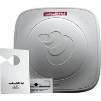
LMHNTG - RFID reader LiftMaster - Free user manual and instructions
Find the device manual for free LMHNTG LiftMaster in PDF.


| Product Type | Long Range RFID Reader |
| Brand | LiftMaster |
| Model | LMSC1000 |
| Part Number | LMSC1000 |
| Dimensions (L x W x H) | 26 cm x 26 cm x 3.8 cm |
| Weight (reader only) | 0.88 kg |
| Power Supply | 12 VDC, 3A (regulated power supply included) |
| Frequency Range | 902 MHz - 928 MHz |
| Supported Protocol | ISO 18000-6C/EPC C1 G2, ISO 18000-6B |
| Read Range | 6.09 to 9.14 m (20 to 30 ft) depending on tag |
| Anti-collision | Up to 100 tags/second |
| Polarization | Circularly polarized |
| RF Output Power | Adjustable 13 to 30 dBm (1 dB steps, accuracy +/- 0.5 dBm) |
| Connectivity | 26-bit Wiegand (D0, D1, GND) |
| Operating Temperature | -20°C to 50°C |
| Storage Temperature | -20°C to 80°C |
| Protection Rating | Requires weatherproof enclosure (not included) |
| Box Contents | Reader, 12V/3A power supply, mounting bracket, U-bolts (2), S2W Wiegand interface module |
| Tag Compatibility | LiftMaster RFID tags LMHNTG, LMUNTG (ordered separately) |
| Installation | Wall or pole mount, adjustable orientation, cabling up to 15.2 m (power) and 107 m (Wiegand) |
| Maintenance & Cleaning | Clean with a soft dry cloth. Do not use abrasive cleaners or solvents. |
| Safety | Complies with FCC Part 15 and ISED. Warning: lead exposure (California Proposition 65). |
| Replacement Parts | Mounting bracket K-AUMB, Wiegand module K-S2W, power supply KSC12-3A |
| Warranty | 1 year limited (parts and labor) |
Frequently Asked Questions - LMHNTG LiftMaster
User questions about LMHNTG LiftMaster
0 question about this device. Answer the ones you know or ask your own.
Ask a new question about this device
Download the instructions for your RFID reader in PDF format for free! Find your manual LMHNTG - LiftMaster and take your electronic device back in hand. On this page are published all the documents necessary for the use of your device. LMHNTG by LiftMaster.
USER MANUAL LMHNTG LiftMaster
The LiftMaster proprietary Long Range Reader and vehicle tags provide you quick and easy access into your gate. The LiftMaster reader and vehicle tags must be used as a system in order to function. The LiftMaster branded tags can only be used with the LiftMaster branded reader. For use with the CAPXL, CAP2D, EL2000SS and EL25.
Carton Inventory
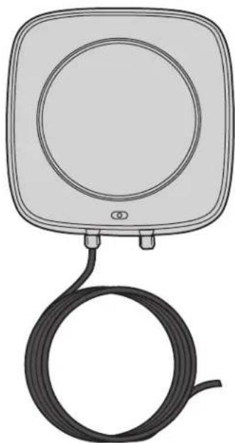
LMSC1000 Reader

12V 3A Regulated Power Supply
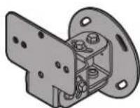
Mounting Bracket
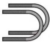
U-Bolts (2)
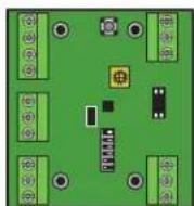
S2W Wiegand Interface Module
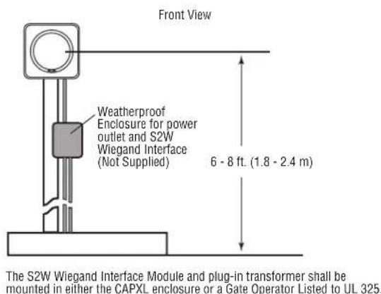
The S2W Wiegand Interface Module and plug-in transformer shall be mounted in either the CAPXL enclosure or a Gate Operator Listed to UL 325.
Supported LiftMaster RFID tags (Order Separately)

LMHNTG/SPLMHNTG * LiftMaster RFID Hang tag
LMUNTG/SPLMUNTG*
LiftMaster Dual-Purpose RFID
Tag (Windshield/Headlamp)
* If specific Facility Code and Start ID required, use special part #s SPLMHNTG, SPLMUNTG.
LIFTMASTER LONG RANGE RFID READER Model LMSC1000

WARNING: This product can expose you to chemicals including lead, which are known to the State of California to cause cancer or birth defects or other reproductive harm. For more information go to www.P65Warnings.ca.gov.
Reader Specifications
| Part Number LMSC1000 | |
| FCC ID XVY-IDRO900MA | |
| Dimensions 10.25" x 10.25" x 1.5" | |
| Polarization Circular Polarized | |
| Frequency range 902Mhz | ~ 928 MHz |
| Supported Protocol ISO | 18000-6C/EPC C1 G2, ISO 18000-6B |
| Read Range 20 – 30 Feet | (Depending on Tag) |
| Anti-Collision Up to 100 tags/second | |
| Environment Operating Temp : - 20 C to + 50 CStorage Temp : - 20 C to + 80 C | |
| Connectivity 26-Bit Wiegand (D0, D1, GND) | |
| Power Supply 12 VDC, 3A | (cable run max 50' (15.2 m) with an 18 gauge stranded or larger wire. Minimum voltage 11.5 under load. |
| RF Output Power | Adjustable 13-30 dBm with 1 dB stepsPower Accuracy +/- 0.5dBm |
| Weight | < 31.0 oz. (Reader Only) |
| Protocol | ISO18000-6C C1G2 |
| Firmware | v.EI8070400 |
Installation
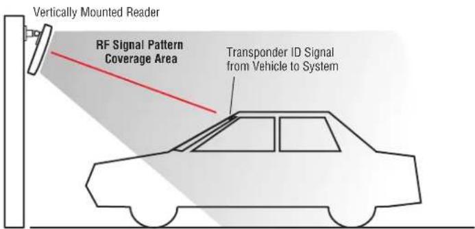
Site layout plays a large role in where you can mount the reader and may prompt you to use a particular location/orientation. It is very important to be mindful of how reader placement affects where and how you mount the RFID tags/transponders on the vehicle. Here are some examples of reader placement and how they affect tag placement.
Orientation Note: Minimize the distance between reader and tag as much as possible (shown as red line).
For best results use a signal checker to test desired installation position. After reader orientation has been selected make sure that all readers to be used at the site are installed in the same orientation to ensure consistent tag reads (all on the left/driver's side, for example).
The example shown is a general recommendation, fi nal location should be decided after fi eld testing.
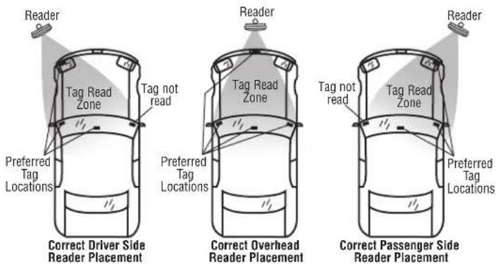
NOTE: Use LMHNTG for rear view mirror tag location and LMUNTG for all other tag locations.
Reader Mounting
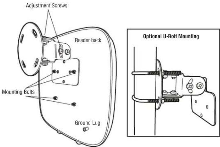
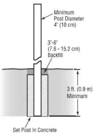
Step 1: Install mounting bracket to the desired mounting location. Attach the round side of the bracket with appropriate screws.
Step 2: Secure the reader to the mounting bracket by removing the mounting nuts from the mounting bolts located on the back of the reader. Place the reader bolts through the mounting bracket's supplied holes. Reinstall the mounting nuts/lock washers and re-tighten.
Step 3: Once the reader is mounted, the reader's vertical orientation to the roadway can be adjusted using the adjustment screws. The specific angle is determined by the average pitch of the vehicle's tag mounting surface (e.g., windshield, headlamp, etc.).
![graph TD A["Reader"] --> B["Gate"] B --> C["1 ft. (0.3 m)"] C --> D["3 - 4 ft. (0.9 - 1.2 m)"] D --> E["6 - 8 ft. (1.8 - 2.4 m)"] E --> F["Arming Loop"] style A fill:#f9f,stroke:#333 style F fill:#ccf,stroke:#333](/content/2026/04/692533/images/45615298a4e7bc347a047aea92f7d004e102aa5129825fb8c752c3400345ae02.jpg)
NOTE: Examples shown are general recommendations, final location should be decided upon field testing.
Wiegand Interface Module Mounting and Wiring
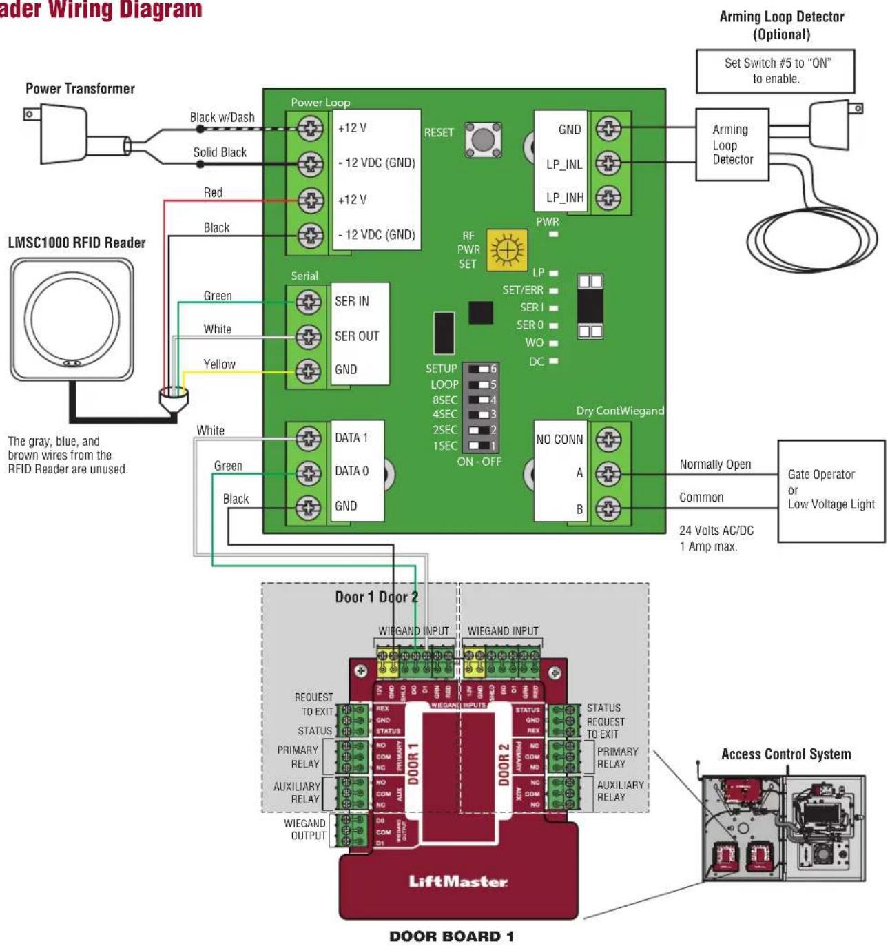
The following are the provisions for the wiring connections on the LMSC1000 reader system.
- Take special precautions to protect the system's components by locating them in a weatherproof enclosure (sold separately).
- In the weatherproof enclosure, provide a properly protected 115VAC power outlet for powering the reader through the provided power supply.
- Once an appropriate weatherproof enclosure with power outlet has been installed, route the reader cable so that it safely enters the enclosure and maintains the enclosure's weatherproof capabilities.
- Route Wiegand Data 0, Data 1, and Common from S2W Wiegand Interface to the access control panel so that it safely exits the enclosure and maintains the enclosure's weatherproof capabilities.
- AC must be run in a separate conduit.
- Maximum cable distance between Reader and S2W Wiegand Interface is 19 feet (5.8 m).
- Maximum cable distance between Reader and access control system is 350 ft (107 m) with 18 AWG wire.
Reader Cable Index Power Supply Index
| Color Function | |
| Yellow Com | |
| Green TXD | |
| White RXD | |
| Black -12 VDC (GND) | |
| Red +12 VDC | |
| Color Function | |
| Solid Black -12 | VDC (GND) |
| Black w/Dash + | 12 VDC |
Reader LEDs
The LEDs on the front of the LMSC1000 Reader will illuminate red when powered. Blinking blue LEDs indicate an RFID tag is being read.
Arming Loop Input (Optional) Dry Contact Relay Output
For applications where multiple RFID readers will be in close proximity this feature can be used to turn on the reader fi eld ONLY when the loop senses the presence of a vehicle.
When switch 5 is turned on, the Wiegand board sends a command to the antenna to turn off the reader fi eld until a vehicle presence is detected.
For applications where RFID tag holders want an external visual or audible notification that the reader processed their tag. The relay contacts change state for 2 seconds with every valid Wiegand output, if time delay is enabled the relay will only pulse once during the selected period.
Low voltage only, 24 Volts AC/DC 1 amp
Reader Wiring Diagram
Wiegand Interface Module LEDs
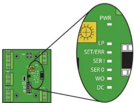
| Green (PWR) Power (Solid) | when power present) |
| Green (LP) Arming Loop (Solid when active) | |
| Blue (SET/ERR) Data Error | Received from Reader |
| Red (SER 1) Data Received | from Reader (Flash) |
| Yellow (SER 0) Data Transmitted to Reader (Flash) | |
| Orange (W0) Wiegand Data | Output (Flash) |
| Orange (DC) Relay Control | Output (Flash) |
Wiegand Interface Module Programming
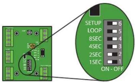
Wiegand Retransmission Delay
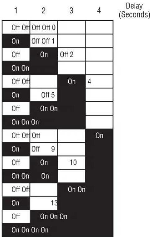
The S2W Wiegand Interface Module has an adjustable Wiegand output retransmission delay from 0-15 seconds. When enabled, the S2W Wiegand Interface will transmit 1 Wiegand pulse and start the timer. If a tag remains in the active reading zone, the S2W Wiegand Interface will not transmit another pulse until the timer expires. The delay is set using the bottom 4 dip-switches shown above. When the switch is set to the left it is in the "On" position. Use the chart to the right to select the desired amount of retransmission delay (in seconds). The default setting is 3 seconds delay.
NOTE: The power to the S2W Wiegand Interface must be cycled for any switch changes to take effect.
Antenna Range Adjustment
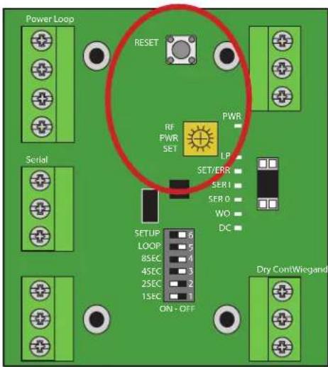
The S2W Wiegand Interface Module has an antenna range adjustment located on the circuit board just left of the LED Display. To adjust the range perform the following steps:
-
Place the module in programming mode by setting switch 6 to "On"(left).
-
Locate the adjustment pot and turn clockwise to increase range or counter-clockwise to decrease range. The LED display will show the relative power setting (Max is all LEDs on).

-
To send the new range setting to the reader press the Reset button just above the range adjustment.
-
Once the desired range is set, place the module into operating mode by setting switch 6 (Setup) to "Off" (right).

Beeper Enable/Disable
By default, the LMSC1000 will beep when it reads an RFID tag. To toggle this feature (turn on or off) perform the following steps:
-
Place the module in programming mode by setting switch 6 (Setup) to "On" (left).
-
Turn the adjustment pot counter-clockwise to the minimum setting.

- Press the Reset button just above the range adjustment to toggle the setting.

-
Return the antenna range setting to its original position.
-
Press the Reset button just above the range adjustment to set range.
-
Place the module into operating mode by setting switch 6 to "Off" (right).
Programming Your LiftMaster tags into myQ® Business™
When adding a new credential in myQ® Business™, go to the credentials tab, click “Add new credentials” and when selecting type, choose RFID_Tags_LiftMaster.
Please note, there is a section option for installations that have a Non LiftMaster Branded RFID system. If the RFID system is anything other than LiftMaster reader (LMSC1000) or LiftMaster RFID tags (LMUNTG/SPLMUNTG or LMHNTG/SPLMHNTG), follow the steps above, except when the drop down menu step comes up, choose RFID_Tags_Other_Mfgs.
Troubleshooting
| Problem Troubleshooting Resolution | ||||
| Reader does not read tags (Reader LED is Red and does not change) | Power Check the power | supply voltage at the closest termination to the reader (typically at the Wiegand interface module) with a Digital Multi-Meter (DMM). You should read >12VDC. | If the wiring distance and gauge are correct and the supply is <12VDC, replace the power supply with another rated at 12VDC 3A. | |
| Measure the wiring distance between the reader (mounted) and where the power supply plugs in to the main power source. This distance should not exceed 50'. | ||||
| Check the wiring gauge to make sure it is within specification for this product (Cat5/6 should never be used for power). | ||||
| If the above all checks out and the reader recovers with a power cycle to both reader and Wiegand module then investigate the main (115VAC) supply. If the main power source experiences a brown out condition (voltage drops below 100VAC but does not go away entirely), this may lock up the reader and cause it to malfunction. | Switch to a separate main power (115VAC) source or install a UPS system to provide a more stable power source. | |||
| Programming Remove | the serial connector (green, white and yellow wires from reader) from the Wiegand interface module and cycle power to both devices. If the reader regains normal function then the issue may be in the Wiegand interface module. | The Wiegand interface has a arming loop feature that will place the RFID reader into standby mode when the loop input is not active. Check the arming loop setting of the Wiegand interface module on dip switch S1-5 and make sure this switch is in the off position. If the setting is off and the problem persists, replace the Wiegand interface module. | ||
| Final If the reader does | not recover after a power cycle and the above troubleshooting does not reveal the problem, there may be an issue internally in the reader. | Contact your channel partner and request an RMA to send in the reader for repair or order a replacement. | ||
| Reader reads RFID tags however not at an adequate range. (The average read range should be 20-25') | Power Check the power | supply voltage at the closest termination to the reader (typically at the Wiegand interface module) with a DMM. You should read >12VDC. | There is a direct correlation between the quality of the power supplied to the reader and the reader range. Make sure that the wiring distance is kept to minimum (no coiled wire), gauge is correct and the supply is >12VDC. If all checks out proceed to the next section under programming. | |
| Measure the wiring distance between the reader (mounted) and where the power supply plugs in to the main power source. This distance should not exceed 50'. | ||||
| Check the wiring gauge to make sure it is within specification for this product (Cat5/6 should never be used for power). | ||||
| RFID Tags You will not | experience normal operating range if you are testing windshield/headlamp mount tags by hand. The tags need the intended mounting surface to achieve normal operating range. | Temporarily mount the tag to intended surface using tape and retest. | ||
| Inspect the mounting of the RFID tags and make sure they are mounted correctly and away from any interference sources. | Consult the RFID tag installation manual and make sure that the tags are mounted correctly. | |||
| Outside Interference RFID readers are susceptible to interference from other electronic devices and environmental conditions. | ||||
| Make sure the reader has free line of sight to the RFID tag on the vehicle in the road way. It cannot be obstructed in any way by foliage (plants, bushes, and trees) or metal (posts, signs, gate arms). | Remove any obstructions that are in front of the reader's read zone. | |||
| Check the area around the installation for other electronic devices that may emit noise and interference such as high voltage power lines, fl orescent lights, cell phone towers, high power UHF radio transmitters or antennas (Including other RFID systems). | Investigate if any of these sources can be temporarily disabled to allow RFID reader testing. If the RFID reader range increases when the device is disabled then you have located the source of interference. You may need to relocate the interference source or RFID reader. | |||
| Programming This reader offers a range adjustment on the Wiegand interface module. This default sets the reader range at maximum however this may have changed. | Confirm the read range setting using the steps in the installation manual. | |||
| No Wiegand data received by Access Controller | System Verify that the | RFID Reader is acknowledging the tag by beeping and/or LED fl ashing blue. | If you do not receive a beep and/or a blue LED fl ash then the reader is not acknowledging the RFID tag. | |
| If the reader LED fl ashes blue, verify the reader is outputting serial data from the reader to Wiegand interface module (WIM). When the reader fl ashes blue there should be a corresponding red LED fl ash on the Wiegand interface. | If there is not a fl ash of the red LED when a tag is read then there is a problem with the serial data feed between the reader and WIM. Double check the wiring between the two devices to make sure all of the connections are correct. You may confirm data output by connecting a computer with serial connection and use a telnet program (such as putty). The settings for the connection should be 9600,8,N,1. You should see raw tag data if you connect to the reader using the following connection (Green - RXD, White - TXD, Yellow - Com). If there is no serial data coming from the reader then the reader has malfunctioned and needs repair. If there is serial data coming from the reader then the problem is in the WIM and it needs to be replaced. | |||
| If the reader LED fl ashes blue and the WIM fl ashes red, check to make sure the top orange LED fl ashes (the initial fl ash should be instant however repeat fl ashes are controlled by the re-transmission control). The orange LED indicates when a Wiegand pulse is sent to the access controller. | If no orange LED fl ash is observed then there is a problem with the WIM and it should be replaced. | |||
| If the reader LED fl ashes blue, WIM fl ashes red and top orange LED fl ashes there may be a wiring issue between the WIM and your access controller. | Make sure your wiring run is less than the maximum distance of 350° (107 m). | |||
| With a DMM, measure for DC voltage between the Data 1 and COM as well as Data 0 and COM. You should read a normal operating voltage of at least 4.9-5VDC. A reading of less than this voltage indicates a voltage drop potentially due to cable distance or poor connections. | ||||
| Disconnect the Wiegand connector from the WIM module (Access Controller still connected) and measure the voltage at the connector. This will test the wiring run from your access controller to WIM and should be >4.9VDC. If you measure 0VDC then there is a break in your wiring run. | ||||
| Disconnect the Wiegand connection from the Access Controller (WIM still connected) and measure the voltage at the connector. This will test the wiring run from your WIM to Access Controller and should be >4.9VDC. If you measure 0 VDC then there is a break in your wiring run. | ||||
| Printed RFID Tag IDs do not match what is received on the access controller. | Programming The Wiegand interface outputs 26-bit Wiegand data. Make sure that the access controller you are using is set to receive 26-bit Wiegand inputs. | Try swapping the Data 0 and Data 1 wires at either the Wiegand interface or access controller and retest. | ||
| Reader is sending too many tag reads to the access controller. | Programming The factory default is to send a Wiegand output for every tag read made by the RFID reader. This is adjustable and a delay can be programmed to minimize the Wiegand outputs sent to the controller. | Change the Wiegand re-transmission delay setting (0-15 seconds) using the steps in the installation manual. | ||
Service Parts
| Part Part Number | |
| Mounting Bracket K-AUMB RFID Bracket | |
| Wiegand Interface Module K-S2W Wiegand Interface Board | |
| RF Power Supply - 3 amps KSC12-3A | |
One Year Limited Warranty
LiftMaster warrants to the first consumer purchaser of this product that it is free from defect in materials and/or workmanship for a period of 1 year from the date of purchase.
NOTICE: This device complies with Part 15 of the FCC rules and Industry Canada's license-exempt RSSs. Operation is subject to the following two conditions: (1) this device may not cause harmful interference, and (2) this device must accept any interference received, including interference that may cause undesired operation. Any changes or modifications not expressly approved by the party responsible for compliance could void the user's authority to operate the equipment.
This device has been tested and found to comply with the limits for a Class B digital device, pursuant to part 15 of the FCC rules and Industry Canada ICES standard. These limits are designed to provide reasonable protection against harmful interference in a residential installation. This equipment generates, uses and can radiate radio frequency energy and, if not installed and used in accordance with the instructions, may cause
harmful interference to radio communications. However, there is no guarantee that interference will not occur in a particular installation. If this equipment does cause harmful interference to radio or television reception, which can be determined by turning the equipment off and on, the user is encouraged to try to correct the interference by one or more of the following measures:
- Reorient or relocate the receiving antenna.
- Increase the separation between the equipment and receiver.
- Connect the equipment into an outlet on a circuit different from that to which the receiver is connected.
- Consult the dealer or an experienced radio/TV technician for help.
LiftMaster®
LECTEUR RFID DE LONGUE PORTÉE LIFTMASTER
Modèle LMSC1000
Introduction
Lecteur LMSC1000
Délai de retransmission Wiegand
Lector LMSC1000
- SUPPORTED LIFTMASTER RFID TAGS (ORDER SEPARATELY)
- LIFTMASTER LONG RANGE RFID READER MODEL LMSC1000
- INSTALLATION
- READER MOUNTING
- WIEGAND INTERFACE MODULE MOUNTING AND WIRING
- READER LEDS
- ARMING LOOP INPUT (OPTIONAL) DRY CONTACT RELAY OUTPUT
- WIEGAND INTERFACE MODULE PROGRAMMING
- WIEGAND RETRANSMISSION DELAY
- ANTENNA RANGE ADJUSTMENT
- BEEPER ENABLE/DISABLE
- PROGRAMMING YOUR LIFTMASTER TAGS INTO MYQ® BUSINESS™
- ONE YEAR LIMITED WARRANTY
- LIFTMASTER®
- LECTEUR RFID DE LONGUE PORTÉE LIFTMASTER
- MODÈLE LMSC1000
- INTRODUCTION
- DÉLAI DE RETRANSMISSION WIEGAND
Brand : LiftMaster
Model : LMHNTG
Category : RFID reader