WB-430 - Thermal camera VOLTCRAFT - Free user manual and instructions
Find the device manual for free WB-430 VOLTCRAFT in PDF.

User questions about WB-430 VOLTCRAFT
0 question about this device. Answer the ones you know or ask your own.
Ask a new question about this device
Download the instructions for your Thermal camera in PDF format for free! Find your manual WB-430 - VOLTCRAFT and take your electronic device back in hand. On this page are published all the documents necessary for the use of your device. WB-430 by VOLTCRAFT.
USER MANUAL WB-430 VOLTCRAFT
GB Operating Instructions
Thermal Imaging Camera
Item no: 2890410 (WB-430)
Item no: 2890411 (WB-420)
Item no: 2890412 (WB-410)
F Mode d'emploi
Caméra thermique
N° de commande 2890410 (WB-430)
N° de commande 2890411 (WB-420)
N° de commande 2890412 (WB-410)
text_image
Technical diagram of a handheld device with numbered parts labeled 1 to 51 Abdeckung:
2 Touchscreen-Display.
natural_image
Thermal imaging comparison showing heat transfer from a device to a heat sink (no text or symbols visible)text_image
C:21.8 22.9 14.5 MANUALtext_image
C:36.8 Below alarm 25.0 H 46.8 H 26.2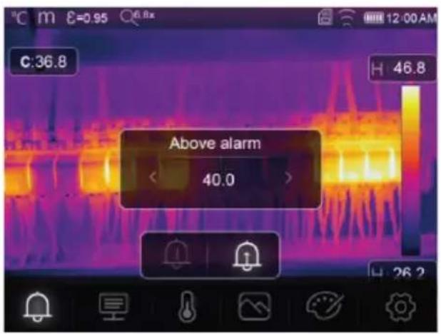
text_image
Above alarm 40.013.2 Parametern
text_image
C:28.8 Parameters 42.7 27.2text_image
C:36.8 H 46.8 Ambient temperature < 25.0 >text_image
C:36.8 Atmospheric Humidity < 60% > H 46.8text_image
C:36.8 Infrared compensation < 0.0 > H 46.8text_image
C:36.8 H 46.8 distance 2.0text_image
C:36.8 H 46.8 Emissivity < 0.95 > &↑text_image
C:36.8 H 46.8 Measurement 26.2
text_image
C:36.8 H 46.8 Center point 26.2text_image
C:31.4 H 32.9 H 27.1 HG Hi 30.0
Hoher Alarm
text_image
C:31.8 HI:32.9 Lo:29.9 A 35.6 A 28.2 AUTOSichtbarer Bereich
text_image
C:36.8 H 46.8 Thermal 26.2Thermisch
text_image
C:36.8 Picture in picture < 68% > Fusion H 46.8 26.2Bild im Bild
text_image
C:36.8 H 46.8 Camera 26.2O Kamera
Nur sichtbares Bild
text_image
C:36.8 Auto fusion H: 46.8 26.2
Automatische Fusion
text_image
C:36.8 H 46.8 26.2
text_image
C:36.8 H 46.8 H 26.21 Introduction.... 41
2 Operating Instructions for download.... 41
3 Intended use 41
4 Delivery contents 41
5 Description of symbols.... 42
6 Safety instructions 42
6.1 General 42
6.2 Handling 42
6.3 Operating environment.... 42
6.4 Operation.... 42
6.5 Power adapter and cable 43
6.6 Li-ion battery.... 43
6.7 Measurement accuracy on low-emissivity surfaces 43
7 Overview.... 44
7.1 General 44
7.2 Control panel buttons 45
7.3 Display.... 46
8 Getting started 46
8.1 Charge the rechargeable battery.... 46
8.1.1 Charging dock (Item No.: 2890410 only) 46
8.1.2 Camera charging input 47
8.1.3 Computer USB port 47
8.2 MicroSD card.... 47
8.2.1 Insert / remove the microSD card 47
8.2.2 Formatting the microSD card 47
9 Emissivity and accuracy 48
9.1 Emissivity setting.... 48
9.2 Accuracy.... 48
10 Menu navigation 48
11 Gesture controls 48
12 Operation.... 48
12.1 Power ON / OFF 48
12.2 Hold readings 49
12.3 Capture photos / videos 49
12.3.1 Photos 49
12.3.2 Video 49
12.3.3 Playback photos / video 49
12.4 Manual image focus (Item No.: 2890410) 49
12.5 Image transform 50
12.5.1 Histogram mode (HG) 50
12.5.2 Automatic mode (AUTO) 50
12.5.3 Manual / lock mode (MANUAL) 51
13 Main menu.... 51
13.1 Alarms 52
13.2 Parameters.... 52
13.2.1 Ambient temperature.... 53
13.2.2 Reflection temperature.... 53
13.2.3 Atmospheric humidity 54
13.2.4 Infrared compensation 54
13.2.5 Distance 54
13.2.6 Emissivity 55
13.3 Measurement 55
13.4 Palette 56
13.4.1 Standard palette 56
13.4.2 High alarm.... 56
13.4.3 Low alarm.... 57
13.4.4 Zone alarm 57
13.4.5 Visible zone 57
13.5 Image modes.... 58
13.5.1 Thermal 58
13.5.2 Picture in picture 58
13.5.3 Camera 58
13.5.4 Auto fusion 59
13.5.5 Zoom 59
13.6 Add text to an image 60
14 Device settings 60
15 Measure settings 61
16 Reset 61
16.1 Erase all files.... 61
16.2 Default settings.... 62
17 PC software 63
17.1 Before installation.... 63
17.2 Install the PC software 63
17.3 Connect to PC (file management) 63
17.4 Connect to PC (Live view).... 64
18 Mobile app 64
19 About the lens (Item No.: 2890410)....65
20 Update the firmware 66
20.1 Check firmware version.... 66
20.2 Download and install new firmware.... 66
21 Troubleshooting.... 66
22 Cleaning and care.... 67
22.1 Housing 67
22.2 Infrared lens 67
23 Declaration of Conformity (DOC).... 67
24 Disposal 68
24.1 Product.... 68
24.2 (Rechargeable) batteries 68
25 Technical data 69
25.1 Product power input 69
25.2 Power adaptor 69
25.3 Rechargeable battery pack 69
25.4 Battery charging cradle 69
25.5 Infrared (IR) imaging performance 69
25.6 Optics 69
25.7 Measurement 70
25.8 Image processing enhancement 70
25.9 Visible light camera 70
25.10 Display.... 70
25.11 Storage and media.... 71
25.12 Measurement units.... 71
25.13 Language setting.... 71
25.14 Data communication interface.... 71
25.15 Wi-Fi 71
25.16 Mobile application.... 72
25.17 Computer software.... 72
25.18 Environment 72
25.19 Physical specifications 72
25.20 Emissivity table.... 72
1 Introduction
Dear customer,
Thank you for purchasing this product.
If there are any technical questions, please contact:
www.conrad.com/contact
2 Operating Instructions for download

Use the link www.conrad.com/downloads (alternatively scan the QR code) to download the complete operating instructions (or new/current versions if available). Follow the instructions on the web page.
3 Intended use
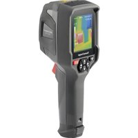
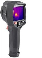
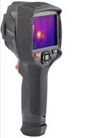
The product is a thermal imaging camera with touch screen display. Some uses include e.g., finding hot spots, energy leaks, structural defects, pipe blockages, and HVAC faults.
Improper use can result in short circuits, fires, electric shocks or other hazards.
The product complies with the statutory national and European requirements.
For safety and approval purposes, you must not rebuild and/or modify the product.
Read the operating instructions carefully and store them in a safe place. Make this product available to third parties only together with the operating instructions.
All company names and product names are trademarks of their respective owners. All rights reserved.
Android ^™ is a trademark of Google LLC.
USB4®, USB Type-C® and USB-C® are registered trademarks of USB Implementers Forum.
4 Delivery contents
Thermal imager
Li-ion rechargeable battery
■ Battery charging dock (Item No.: 2890410 only)
■ Power adapter (US/EU/UK/AU plugs)
■ MicroSD card (32 GB, U1 V10)
■ MicroSD to SD card adapter
USB-A to USB-C® cable
Windows® software CD-ROM
Carry case
- Operating instructions
5 Description of symbols

The symbol warns of hazards that can lead to personal injury.

The symbol warns of dangerous voltage that can lead to personal injury by electric shock.
6 Safety instructions

Read the operating instructions carefully and especially observe the safety information. If you do not follow the safety instructions and information on proper handling, we assume no liability for any resulting personal injury or damage to property. Such cases will invalidate the warranty/guarantee.
6.1 General
The product is not a toy. Keep it out of the reach of children and pets.
Do not leave packaging material lying around carelessly. This may become dangerous playing material for children.
If you have questions which remain unanswered by this information product, contact our technical support service or other technical personnel.
Maintenance, modifications and repairs must only be completed by a technician or an authorised repair centre.
6.2 Handling
- Handle the product carefully. Jolts, impacts or a fall even from a low height can damage the product.
6.3 Operating environment
- Do not place the product under any mechanical stress.
- Protect the appliance from extreme temperatures, strong jolts, flammable gases, steam and solvents.
- Protect the product from high humidity and moisture.
■ Protect the product from direct sunlight.
Do not switch the product on after it has been taken from a cold to a warm environment. The condensation that forms might destroy the product. Allow the product to reach room temperature before you use it.
6.4 Operation
- Consult an expert when in doubt about the operation, safety or connection of the product.
If it is no longer possible to operate the product safely, take it out of operation and protect it from any accidental use. DO NOT attempt to repair the product yourself. Safe operation can no longer be guaranteed if the product:
– is visibly damaged,
– is no longer working properly,
– has been stored for extended periods in poor ambient conditions or
– has been subjected to any serious transport-related stresses.
6.5 Power adapter and cable

Do not modify or repair mains supply components including mains plugs, mains cables, and power supplies. Do not use damaged components. Risk of death by electric shock!
■ Connect the appliance to a wall socket that can be accessed easily.
As power supply, only use the supplied mains adaptor.
Only connect the power adaptor to a normal mains socket connected to the public supply. Before plugging in the power adaptor, check whether the voltage stated on the power adaptor complies with the voltage of your electricity supplier.
■ Never connect or disconnect power adaptors if your hands are wet.
- Never unplug the power adaptor from the mains socket by pulling on the cable; always use the grips on the plug.
For safety reasons, disconnect the power adaptor from the mains socket during storms.
Do not touch the power adapter if there are any signs of damage, as this may cause a fatal electric shock! Take the following steps:
- Switch off the mains voltage to the socket containing the power adapter (switch off the corresponding circuit breaker or remove the safety fuse, and then switch off the corresponding RCD protective switch).
– Unplug the power adapter from the mains socket.
- Use a new power adapter of the same design. Do not use the damaged adapter again.
- Ensure that cables are not pinched, kinked or damaged by sharp edges.
■ Always lay cables so that nobody can trip over or become entangled in them. This poses a risk of injury.
6.6 Li-ion battery
- Never damage the rechargeable battery. Damaging the casing of the rechargeable battery might cause an explosion or a fire!
- Never short-circuit the contacts of the rechargeable battery. Do not throw the battery or the product into fire. There is a danger of fire and explosion!
Charge the rechargeable battery regularly, even if you do are not using the product. Due to the rechargeable battery technology being used, you do not need to discharge the rechargeable battery first. - Never charge the rechargeable battery of the product unattended.
When charging, place the product on a surface that is not heat-sensitive. It is normal that a certain amount of heat is generated during charging.
Risk of overheating, damage, and/or decreased performance. Charge the rechargeable battery within the temperature range: 0 to 50 °C.
6.7 Measurement accuracy on low-emissivity surfaces

WARNING
Risk to personal safety (e.g. burns), fire, or other hazards!
Measuring surfaces with an emissivity ( ) less than 0.60 can lower the accuracy of temperature readings. If precise temperature measurements are critical, consider alternative methods to verify the readings.
7 Overview
7.1 General
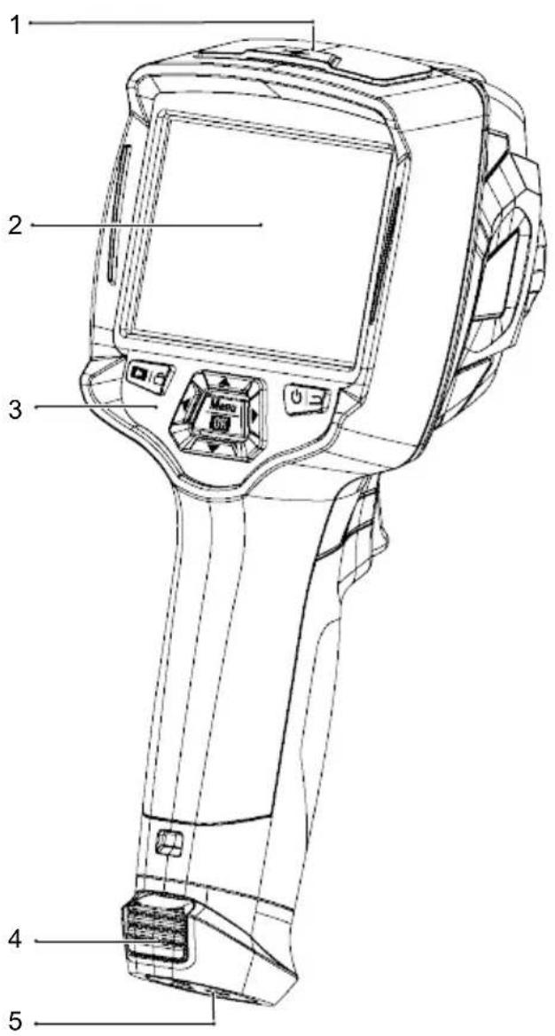
text_image
Technical diagram of a handheld device with numbered parts labeled 1 to 51 Cover:
USB-C® port: data / charging
MicroSD card slot
3 Control panel 4 Release tabs: rechargeable battery
5 Tripod mount 6 Digital (visible light) camera
7 Infrared camera lens 8 Image focus ring
9 Lanyard hole for lens cover 10 Trigger:
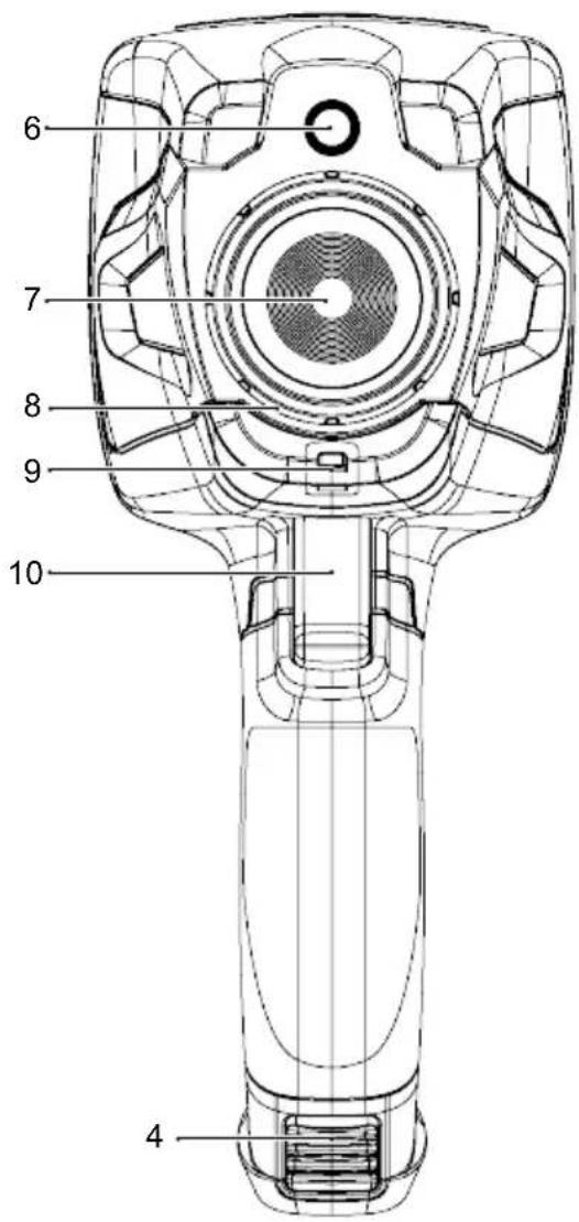
text_image
6 7 8 9 10 42 Touch screen display
Item No.: 2890410 (WB-430) only
Freeze image, capture photo, record video
7.2 Control panel buttons
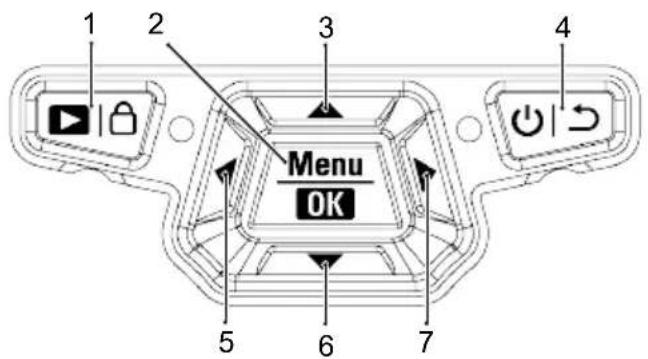
text_image
1 2 3 4 Menu OK 5 6 7| # Icon Description | ||
| 1 |  | Press and hold to playback saved images.Short press to switch between: MANUAL (and AUTO (A) / HG (H) modes. |
| 2 |  | Press to enter the menu.Press and hold to enter the settings menu.Press to confirm a menu selection. |
| 3 | 60×45 | Press to navigate up.Press and hold during measurement to zoom in. |
| 4 | 60×28 | Press and hold to switch the power ON / OFF.Press to return to previous menu. |
| 5 | 60×10 | Press to navigate left.Press and hold during measurement to perform a manual IR calibration. |
| 6 | 60×27 | Press to navigate down.Press and hold during measurement to zoom out. |
| 7 | 60×10 | Press to navigate right. |
7.3 Display
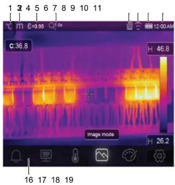
text_image
1 3 4 5 6 7 8 9 10 11 °C m E=0.95 1.0x 12:00 AM C:36.8 H 46.8 image mode H 26.2 16 17 18 19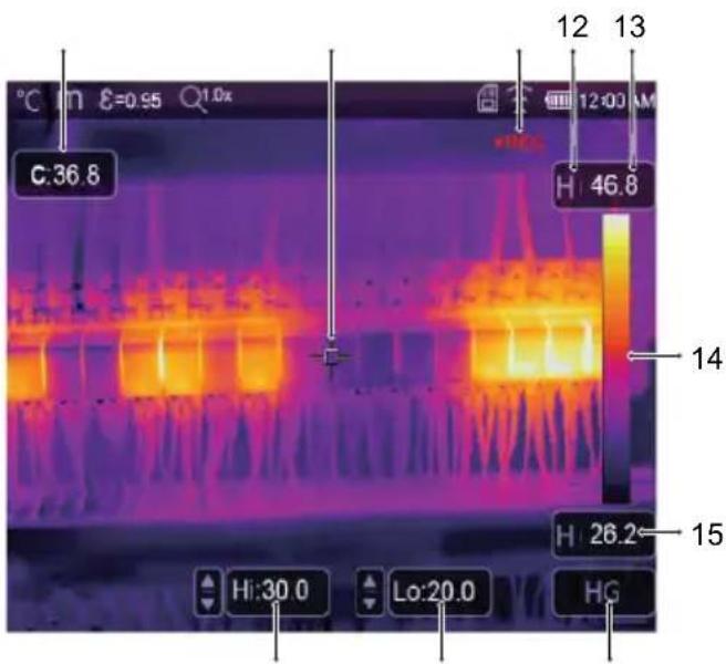
text_image
C:36.8 12 13 H:46.8 14 H:26.2 15 Hi:30.0 Lo:20.0 HG1 Temperature unit 2 Distance unit
3 Emissivity 4 Zoom status
5 MicroSD card 6 Wi-Fi status
7 Battery level 8 Time
9 Centre point temperature 10
11 Video recording
13 Max. temperature of current scene
15 Min. temperature of current scene
17 High temp. alarm (Hi)
19 Active imaging mode: AUTO, HG, MANUAL
Centre point cross
12 Active imaging mode
14 Colour bar
16 Main menu
18 Low temp. alarm (Lo)
8 Getting started
8.1 Charge the rechargeable battery
8.1.1 Charging dock (Item No.: 2890410 only)
- Connect the power adaptor to the USB-C® input port on the charging dock.
- Connect the power adaptor to a mains power outlet.
- Insert the rechargeable battery pack into the charger.
→ The indicator lights will show the charging status.
8.1.2 Camera charging input
Preconditions:
√ Rechargeable battery is inserted into the product.
-
Connect the power adaptor to the TypeC USB/Charge input on the product.
-
Connect the power adaptor to a mains power outlet.
→ The battery icon on the display will show the charging status.
8.1.3 Computer USB port
The USB port must be capable of delivering 5 V/DC for charging to occur.
The rechargeable battery will charge if you connect the TypeC USB/Charge port to a USB port on your computer.
8.2 MicroSD card
Internal storage space will be used to save photos, video and data if no microSD card is inserted.
For further details, see section: Storage and media [▶ 71].
8.2.1 Insert / remove the microSD card
Important:
Make sure the microSD card is oriented correctly before inserting it. Do not use excessive force to push it in.
- Insert the microSD card into slot, it will "click" into place.
→ The microSD card icon will appear.
- Remove using the tip of your finger to press down until it "clicks", then release to eject.
8.2.2 Formatting the microSD card
Important:
- The microSD must be formatted before it can be used to save photos, video and data.
– Always back up important files before formatting the microSD card.
Format the card using the product.
-
Insert the microSD card into the card slot.
-
Navigate to: Menu → Setting → Reset → Format Memory → Yes.
Format the card using a PC computer
The microSD should be formatted using the FAT 16 or 32 filing systems.
Refer to your computer software operating instructions for information about how to do this.
9 Emissivity and accuracy
9.1 Emissivity setting
To increase the accuracy of readings, set an emissivity value that matches the material being measured. The emissivity can be set two ways:
■ Manual setting: Emissivity [▶ 55].
■ Preset values: Measure settings [▶ 61].
A list of common materials and emissivity values can be found here: Emissivity table [▶ 72].
9.2 Accuracy
Configure the parameters to improve accuracy of readings. See section: Parameters [▶ 52].
10 Menu navigation
| Button Function | |
| Menu | Press to enter the menu and submenus. |
| OK | Press to confirm a selection. |
 / press to navigate up / down. / press to navigate up / down. | |
| [TBXZ] / press to navigate left / right. | |
| [ZWGB] | Press to return to previous menu. |
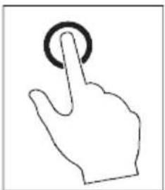
11 Gesture controls
natural_image
Line drawing of a hand with a finger pressing a button (no text or symbols)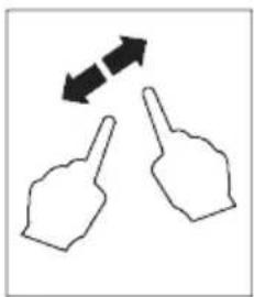
natural_image
Two hand gestures with bidirectional arrows indicating movement (no text or symbols)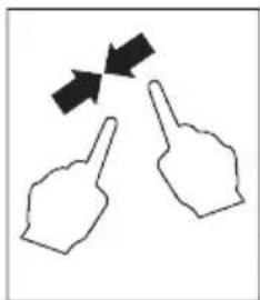
natural_image
Two hand gestures with arrows indicating direction (no text or symbols)
natural_image
Simple line drawing of a hand pointing upward with a downward arrow (no text or symbols)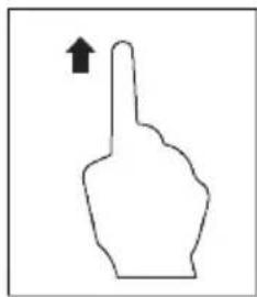
natural_image
Simple line drawing of a hand pointing upward with an arrow (no text or symbols)Select Expand Pinch Slide down Slide up
12 Operation
12.1 Power ON / OFF
- Press and hold the button to switch the power ON.
→ Wait a few moments for the product to self calibrate and display a thermal image.
- Press and hold the button to switch the power OFF.
12.2 Hold readings
- Press the trigger to hold the reading.
→ The reading will be held.
- Press the ⏻ button to release the hold.
12.3 Capture photos / videos
12.3.1 Photos
-
Short press the trigger to capture the measured scene.
-
Press OK touch on the display to save the image.
12.3.2 Video
- Press and hold the trigger to start recording.
→ The icon will show to indicate recording is in progress.
- Short press the trigger to stop recording.
12.3.3 Playback photos / video
Playback will first recall photos / video from an inserted microSD card. Remove the microSD card to playback from internal storage.
-
Press and hold the button.
-
Press ↗ to navigate.
-
Press OK access further options e.g., play video, view file info., delete viewed file.
Tip:
View saved photos / video on a PC. See section: Connect to PC (file management) [▶ 63].
12.4 Manual image focus (Item No.: 2890410)
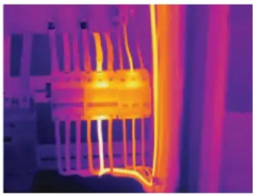
For improved accuracy, the image should be in focus so infrared energy is directed onto the pixels of the detector.
■ Item No.: 2890410 has a manual image focus ring.
■ Use the image focus ring to adjust the sharpness.
natural_image
Thermal image showing heat distribution with warm yellow-orange core and cooler purple background (no text or symbols)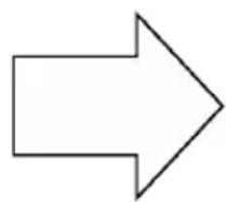
natural_image
Thermal imaging view of a heat exchanger or cooling unit with visible cooling fins and heat distribution (no text or symbols)12.5 Image transform
Select a mode (Histogram, Automatic, or Manual) to optimize temperature visualization based on the complexity of the scene, consistency of temperature ranges, or specific user-defined parameters.
Tips:
- Touch the display to toggle between modes: AUTO, HG, or MANUAL.
- If "AUTO", "HG" mode does not appear, activate it here: Menu → Setting → Measure setting → Image Transform → HG / AUTO.
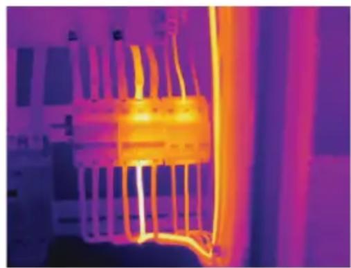
12.5.1 Histogram mode (HG)
text_image
H 8.15 Lo 13.6 H 84.5 H 15.6 HGThe thermal image is enhanced using a histogram algorithm. The color-temperature relationship is not linear, which may improve detail and contrast.
This mode is suited for complex scenes where subtler temperature gradients need to be highlighted.
- Short press the button to toggle between "HG" and "MANUAL" mode.
- "H" and "HG" will appear to indicate automatic mode is active.
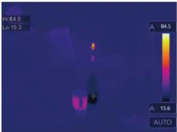
12.5.2 Automatic mode (AUTO)
text_image
Hi 84.5 Lo 15.3 A 84.5 A 15.6 AUTOAdjusts the thermal image automatically based on the detected minimum and maximum temperatures.
The color-temperature relationship for this setting is linear and suited for consistent, routine monitoring where temperature ranges are known and stable.
- Short press the button to toggle between "AUTO" and "MANUAL" mode.
- "A" and "AUTO" will appear to indicate automatic mode is active.
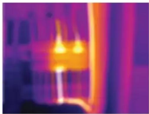
12.5.3 Manual / lock mode (MANUAL)

text_image
C:21.8 22.9 14.5 MANUALThe temperature level is determined by user-set upper and lower temperature limits.
It is suited for situations where a specific temperature band is targeted for observation.
- Short press the button to activate / deactivate this mode.
→ The icon and "MANUAL" will appear to indicate manual mode is active.
- Touch the upper or lower temperature values to manually adjust them.
13 Main menu
| Icon Setting Section links | ||
 | Alarm | Set high / low temperature alarm values.See section:Alarms [▶ 52]. |
 | Parameters | Set parameters for increased accuracy.See section:Parameters [▶ 52]. |
| [XEZW] | Measurement | A selection of various temperature metering modes.See section:Measurement [▶ 55]. |
| [40YZ] | Image mode | Select how images are overlaid on the display.See section:Image modes [▶ 58]. |
 | Palette | Select how thermal images are color rendered.See section:Palette [▶ 56]. |
 | Setting | Access various system settings.See section:Device settings [▶ 60]. |
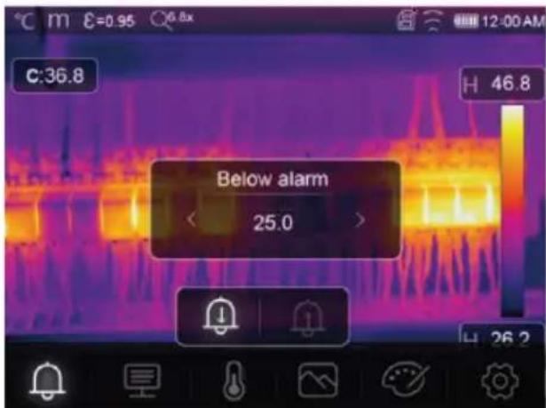
13.1 Alarms
- Select an alarm type: Menu → Setting → Measure setting.
| Alarm type Description | |
| OFF Disable alarm sound. | |
| Above alarm If the object temperature is above than set value, the alarm will activate. | |
| Below alarm If the object temperature is less than set value, the alarm will activate. | |
| Zone alarm If the object temperature between high and low values, the alarm will activate. | |
- Set the temperature values:
text_image
C:36.8 Below alarm 25.0 H 46.8 H 26.2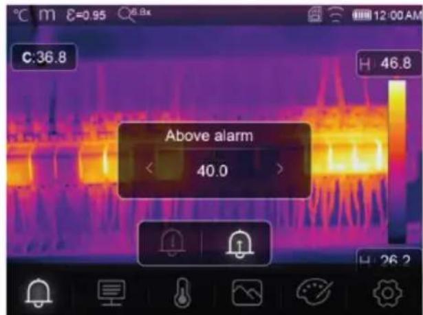
text_image
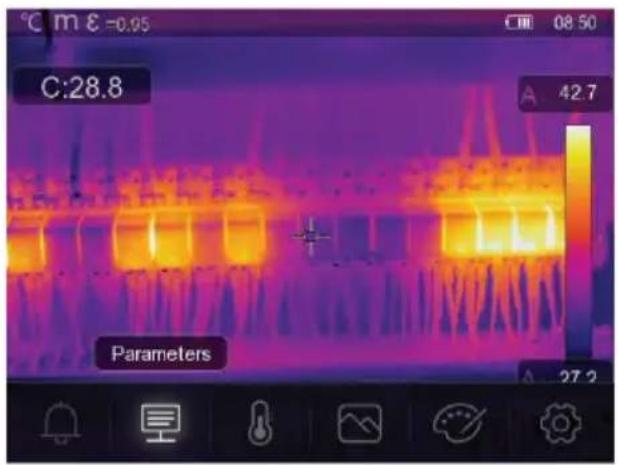
C:36.8 Above alarm < 40.0 > H 46.8 H 26.213.2 Parameters
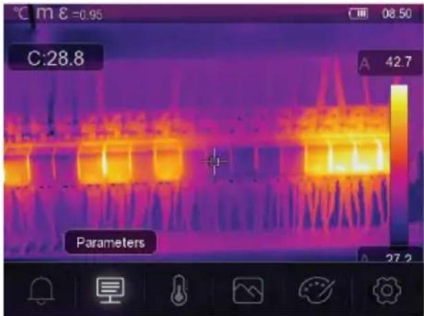
text_image
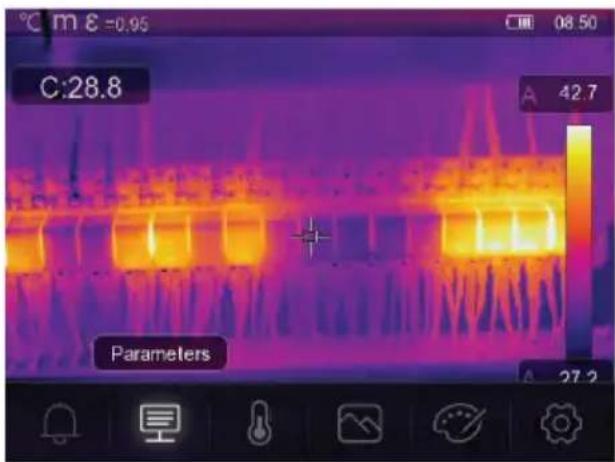
C:28.8 Parameters 42.7 08.50 27.2■ Set parameters to enhance the accuracy of temperature measurements.
■ Each parameter addresses a variable that can affect the precision of the thermal readings.
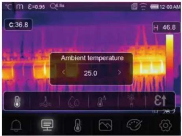
13.2.1 Ambient temperature
text_image
C:36.8 H 46.8 Ambient temperature < 25.0 >■ Deviations from the default temperature setting can affect the accuracy of readings.
Adjust the settings to match the ambient temperature.
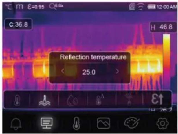
13.2.2 Reflection temperature
Objects reflect infrared energy coming from surrounding objects. Reflected energy is added to the energy of the object itself, potentially causing measurement errors. Results are more likely to be affected with objects that have low emissivity.
In most applications (especially objects with high emissivity), the reflected temperature will reach an equilibrium with the ambient temperature. This has a minimal effect on temperature measurements.
In environments with higher temperature sources close to the object being measured, it is necessary to compensate for reflected energy by setting a temperature value for the environmental heat source.
text_image
C:36.8 H 46.8 Reflection temperature < 25.0 >-
Set the emissivity to 1.00. See section: Emissivity [▶ 55].
-
Point the lens 180^ away from object to be measured.
-
Take a measurement and then press the trigger to hold (freeze) the image.
-
Determine the average value of the image.
→ Average value: take multiple readings and divide by number of readings taken.
- Input the value via the onscreen settings.
→ This setting will be factored in to create a temperature reading adjustment to account for reflected energy.
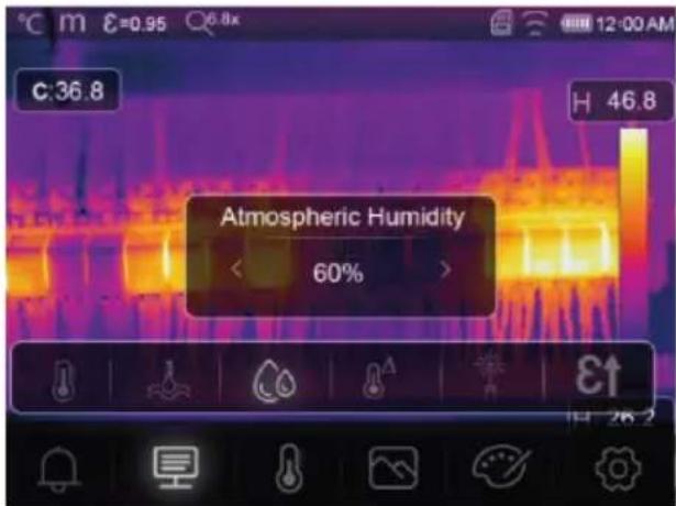
13.2.3 Atmospheric humidity
text_image
C:36.8 H 46.8 Atmospheric Humidity < 60% >■ Water droplets in the air can absorb infrared rays, and affect the accuracy of readings.
- Adjust the settings to match the humidity levels.
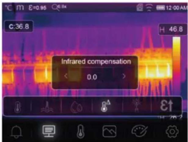
13.2.4 Infrared compensation
text_image
C:36.8 Infrared compensation < 0.0 > H 46.8■ Various factors can affect measurement accuracy (e.g., accuracy drift over time).
In automatic mode, set a compensatory value if there is a known discrepancy between the measured temperature and the actual object temperature.
13.2.5 Distance
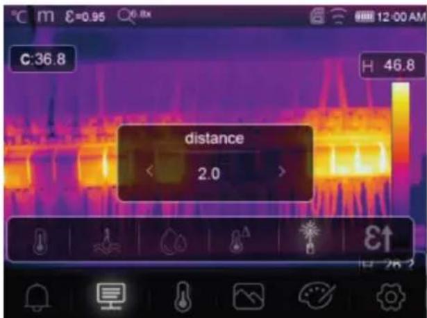
text_image
C:36.8 H 46.8 distance 2.0Infrared energy reduces as the distance from the measured object increases.
Adjust for this by entering the distance to the measured object.
13.2.6 Emissivity
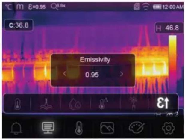
text_image
C:36.8 H 46.8 Emissivity < 0.95 > ε↑ 28.7■ Emissivity settings can be adjusted manually, and in smaller increments.
For further information on emissivity see: Emissivity and accuracy [▶ 48]
13.3 Measurement
Various modes can be selected for temperature measurement.
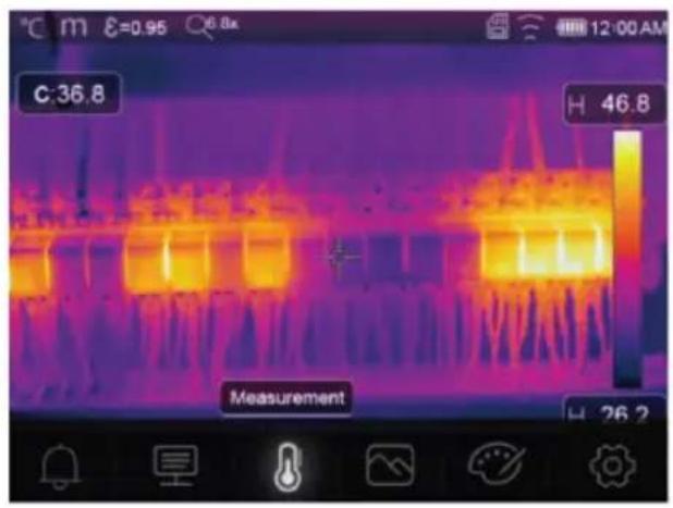
text_image
C:36.8 H 46.8 Measurement H 26.2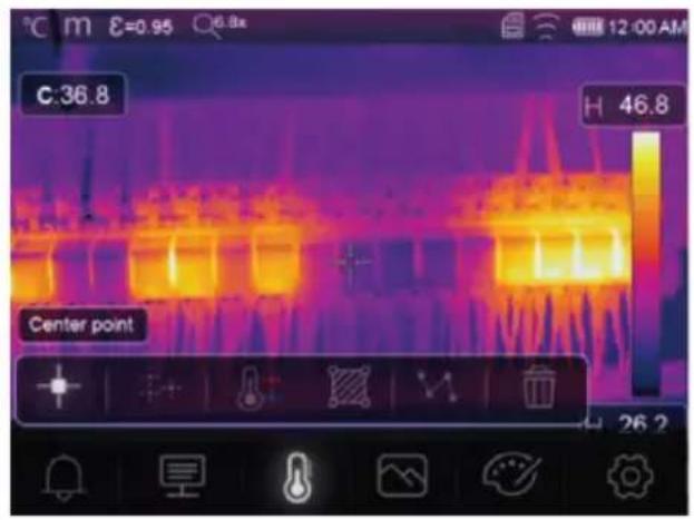
text_image
C:36.8 H 46.8 Center point 26.2To access measurement settings: Menu → Measurement.
| Icon Type | Description | |
| Center point | Measure the temperature at a fixed center point. | |
| Measure point | Manually position measurement points.Tip: Touch the icon to set up to three point measurement zones. | |
| High/Low | Capture the max./min. temperature. | |
| Area | Measure temperatures within a defined area.Tip: Touch the icon to set up to three measurement zones. | |
| Line | Measure the line temperature.There are two analysis lines (1x horizontal, 1x vertical). | |
| No measurement | Remove all temperature analysis tools from the screen. |
Tip:
Use the touch screen to move or resize the temperature assessment area. See section: Gesture controls [▶ 48].
13.4 Palette
A variety of palettes are available for specific applications.
Pallets change the false-color presentation of infrared images displayed or captured.
13.4.1 Standard palette
The standard palettes offer an equal, linear presentation of colours that allow for best presentation of detail.

Palette
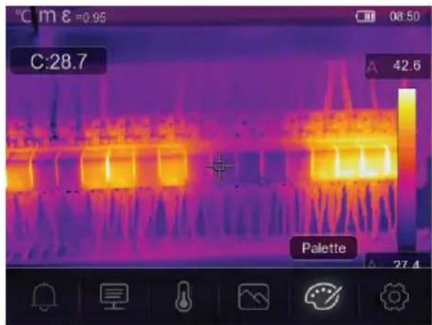
text_image
C:28.7 42.6 Palette 27.4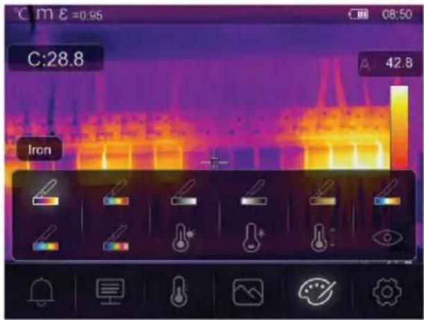
text_image
C:28.8 A 42.8 Iron


Iron Rainbow White hot Black hot Brown hot Blue red Hot cold Feather
13.4.2 High alarm
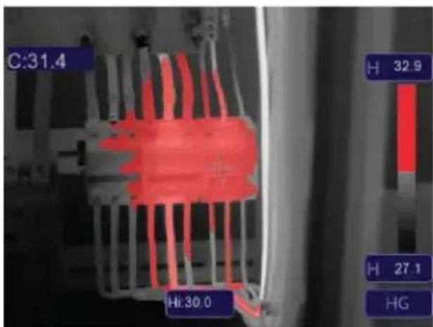
text_image
C:31.4 H 32.9 Hi:30.0 H 27.1 HG
High alarm
■ Temperatures above the value set for the high alarm will be coloured red.
13.4.3 Low alarm
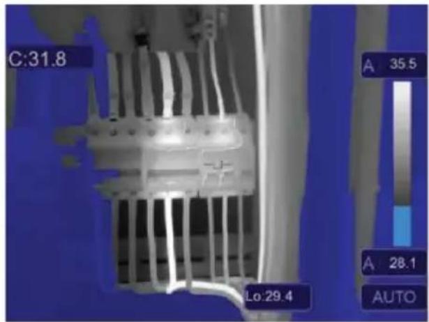
text_image
C:31.8 A 35.5 A 28.1 AUTO Lo:29.4\* Low alarm
■ Temperatures below the value set for the low alarm will be coloured blue.
13.4.4 Zone alarm
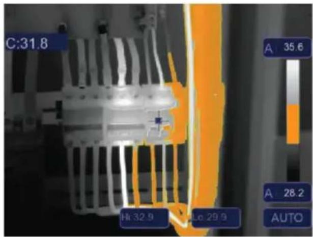
text_image
C:31.8 Hi 32.9 Lo 29.9 A 35.6 A 28.2 AUTOZone alarm
■ Temperatures between the values set for high and low alarms will be coloured orange.
13.4.5 Visible zone
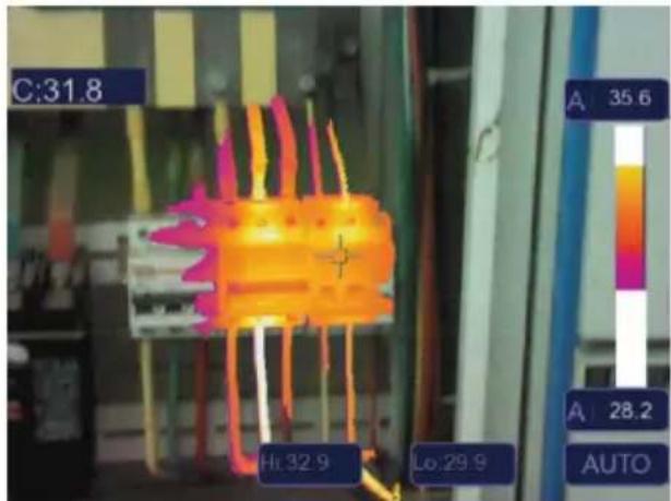
text_image
C:31.8 Hi:32.9 Lo:29.9 A 35.6 A 28.2 AUTOVisible zone
■ Temperatures between the values set for high and low alarms will show as the active pallette.
All other areas will display as the visible image.
13.5 Image modes
13.5.1 Thermal
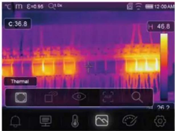
text_image
C:36.8 H 46.8 Thermal 26.2Thermal
An infrared image is displayed.
13.5.2 Picture in picture
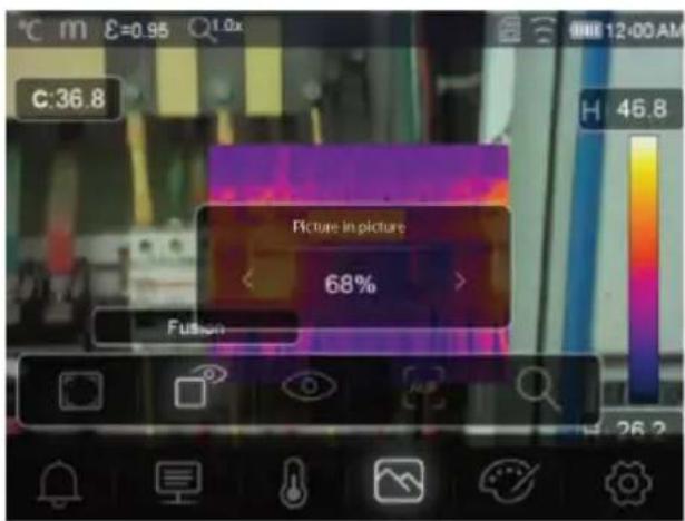
text_image
C:36.8 Picture in picture 68% FusionPicture in picture
Infrared with visible image overlay.
- Adjust the overlay opacity.
Drag the overlay box to reposition it on the touchscreen display.
13.5.3 Camera
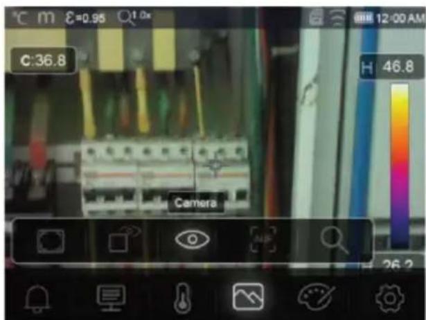
text_image
C:36.8 Camera H 46.8 26.2Camera
Visual image only
13.5.4 Auto fusion
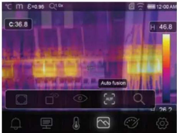
text_image
C:36.8 H 46.8 Auto fusion
Auto fusion
■ Center area temperature is compared with the full screen area.
The ratio of infrared to visible image is calculated automatically.
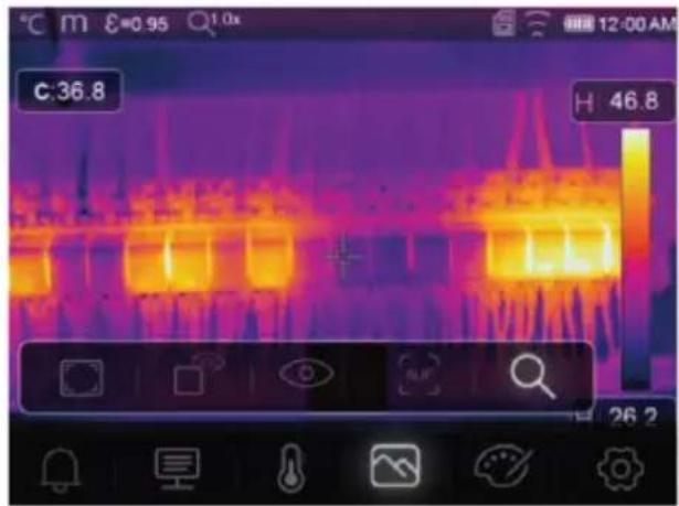
13.5.5 Zoom

Zoom
■ Zoom in / out using the buttons:
■ Zoom in / out using the touch screen slider.

text_image
C:36.8 46.8 26.2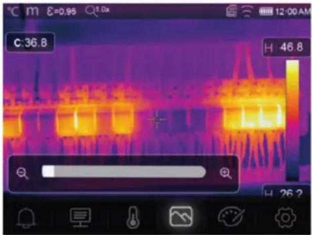
text_image
C:36.8 H 46.8 H 26.213.6 Add text to an image
T Text Information
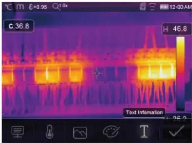
text_image
C:36.8 H 46.8 Text InformationAdd a text note to an image before saving it.
- Short press the trigger to capture the measured scene.
- Press ◀ and navigate to . T
- Press OK enter the menu.
- Enter a note and select to save the note.
14 Device settings
To access device settings: Menu → Setting → Device setting.
| Setting Description | |
| USB Mode Select between two different connection modes:■ USB Driver:- When connected to a computer, the product will show up as a removable disk- After launching the PC software it will enter file management mode.■ PC Software:- After launching the PC software it will enter live view mode.See section: Connect to PC (file management) [▶ 63]. | |
| Brightness | ■ Adjust the display brightness. |
| WIFI | ■ WIFI: Switch Wi-Fi ON/OFF.■ SSID: Change the SSID.■ Password: Change the Wi-Fi password. |
| Time/Date | ■ Set the time and date. |
| Date/Format | ■ Set a date format. |
| Language | ■ Change system language. |
| Auto Power Off | ■ Disable auto power off.■ Set the auto power off time. |
| About | ■ View device information (e.g., model, serial number, firmware version, storage capacity). |
15 Measure settings
To access measure settings: Menu → Setting → Measure setting.
| Setting Description | |
| Distance Unit | ■ m (meters), ft (feet)■ Conversion: 1 (ft) = 0.3048 (m); 1 (m) = 3.2808399 (ft). |
| Temp. Unit | ■ °C (Celcius), °F (Fahrenheit) and K (Kelvin).■ Conversion: °F = 1.8 x °C + 32, K = 273.15 + °C. |
| Temp. Range | ■ If there is an overlap between the two ranges, select: -20 to +150 °C for greater accuracy. |
| Emissivity | Choose from a selection of presets. See section: Emissivity table [▶ 72]. |
| Alarm mode Choose an alarm | setting:■ OFF■ Above temperature■ Below temperature■ Zone alarmTo configure alarm temperature values, see section: Alarms [▶ 52]. |
| Auto Calibration | ■ Select a calibration time interval.■ TIP: Press and hold during measurement to perform a manual IR calibra-tion.1. Press and hold the button.2. "IR calibrating..." will appear on the display during calibration. |
| Image transform | ■ Select between "AUTO" and "HG" modes.■ See section: Image transform [▶ 50]. |
| Align image Adjust the IR over | overlay (x, y axis) so it lines up with the visual image. |
16 Reset
16.1 Erase all files
Important:
This function erases the memory. Always back up important files before clearing the memory.
- If a microSD card is inserted, this function will clear all files on the microSD card.
- If no microSD card is inserted, this function will clear the internal memory.
To clear the memory: Menu → Setting → Reset → Format Memory → Yes.
16.2 Default settings
To return to factory defaults: Menu → Setting → Reset → Default settings → Yes.
| Item Parameter Value | ||
| Wi-Fi SSID Device model number | ||
| Password 12345678 | ||
| Measurement Center spot ON | ||
| Hot spot OFF | ||
| Cold spot OFF | ||
| Measurement parameters Emissivity 0.95 (water) | ||
| Image Mode Infrared | ||
| System setting | Language English | |
| USB mode | USB Driver | |
| Parameters Ambient temperature | 25.0 | |
| Reflection temperature | 25.0 | |
| Atmospheric humidity | 60% | |
| Infrared compensation | 0.0 | |
| Distance (meters) | 2 | |
| Emissivity 0.95 | ||
17 PC software
17.1 Before installation
1. Check .NET framework requirement
The software requires .NET Framework 4.6. This version is included with Windows® 10 by default.
If you are using Windows 8.1 or Windows 7 (with Service Pack 1), you may need to install or update to .NET Framework 4.6.
2. Install .NET framework software (if required)
Important:
Always download the framework from official Microsoft sources to maintain the security and integrity of your system.
If you do not have .NET Framework 4.6, you can download and install it from the official Microsoft website. Search for: "Microsoft .NET Framework 4.6".
After downloading, open the .NET Framework 4.6 installer and follow the instructions to complete the installation process.
17.2 Install the PC software
- Insert the CD-ROM into an available drive on your computer.
- Follow the on screen instructions to complete the installation process.
17.3 Connect to PC (file management)
Use this mode to manage the files, and images on your device using:
Windows file management.
■ Included PC software file management.
Preconditions:
√ The PC software is installed on your PC.
- Load the PC software.
- Enable "USB Driver" mode: Menu → Setting → Device Setting → USB Mode → USB Driver.
- Press repeatedly to exit the menu and return to the main screen.
- Connect one end of the USB cable to the TypeC USB port on the product, and the other end to an available USB port on your PC computer.
→ You can now manage your files on your PC.
17.4 Connect to PC (Live view)
Use this mode to configure settings, control functions, view live readings and more.
Preconditions:
√ The PC software is installed on your PC.
- Load the PC software.
- Enable "USB Driver" mode: Menu → Setting → Device Setting → USB Mode → PC Software.
- Press repeatedly to exit the menu and return to the main screen.
- Connect one end of the USB cable to the TypeC USB port on the product, and the other end to an available USB port on your PC computer.
- A new menu option "Camera" will appear on the software interface. Select it to enter live view.
→ You can now use your PC computer to configure settings, control functions, and view live readings.
18 Mobile app
- Compatible Android™ and iOS apps are available from their respective app stores.
■ Search for: Voltcraft Thermal Imaging.
Some features include: live view, image to phone transfer, and various camera settings control.
To connect to the app:
Preconditions:
√ The application is installed on your mobile device.
-
On the thermal camera navigate to: Menu → Setting → Device Setting → WIFI → WIFI (ON).
→ The Wi-Fi status will show on the display. -
Press repeatedly to exit the menu and return to the main screen.
-
On the mobile device connect to the thermal camera Wi-Fi "SSID" and enter the "Password" [default:12345678].
→ You are now connected to the thermal camera via Wi-Fi.
- Launch the mobile app.
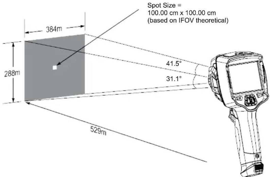
19 About the lens (Item No.: 2890410)
| Focal length FOV (horizontal) FOV (vertical) IFOV* | |||
| 9 mm 41.5° 31.1° | 1.89 mrad | ||
FOV (Field of view)
This is the largest area the imager can capture at a set distance.
IFOV (Instantaneous field of view)
This is the smallest object that the temperature can be measured accurately by the thermal imager.
Unit: rad
■ Formula: IFOV = (pixel size) / (lens focal length).
D:S theoretical (=1 / IFOV theoretical) is the calculated spot size based on the pixel size of the detector array and lens focal length.
Example
Lens = 9 mm, pixel size = 17 μm, FOV (horizontal) = 41.5°, FOV (vertical) = 31.1°, IFOV = 17 μm / 9 mm = 1.89 mrad.
D:S theoretical (= 1 / IFOV theoretical) = 529:1.
text_image
Spot Size = 100.00 cm x 100.00 cm (based on IFOV theoretical) 384m 288m 41.5° 31.1° 529mD:S measure (= 1 / IFOV measure) is the spot size needed to provide an accurate temperature measurement.
D:S measure is typically 2 to 3 times smaller than D:S theoretical. This means the temperature measurement area of the target needs to be 2 to 3 times larger than that determined by the calculated theoretical D:S.
20 Update the firmware
20.1 Check firmware version
To check the firmware: Menu → Setting → Device Setting → About → Software.
20.2 Download and install new firmware
Any firmware updates will be available for download here: www.conrad.com/downloads.
- Download the files to your computer.
- Connect the product to your PC computer in file management mode. See section: Connect to PC (file management) [▶ 63].
- The product will appear as a drive letter on your computer.
- Drag and drop the firmware file to the drive letter.
→ Wait a few moments for the file to finish copying.
-
Disconnect the cable and follow the onscreen prompts to complete the firmware upgrade.
-
Restart the product.
-
Check the firmware version to verify the update.
21 Troubleshooting
| Problem Possible cause Suggested solution | ||
| Power will not switch ON Rechargeable battery flat, or faulty power supply. | Charge the rechargeable battery and/or check the power supply. | |
| Power switches OFF during use | No power Charge the rechargeable battery. | |
| Thermal image not shown Lens cover still attached Remove the lens cover. | ||
| Temperature readings not accurate | Incorrect emissivity values set Check the emissivity values are correct for the material being measured.See: Emissivity table [▶ 72]. | |
| Poor image contrast Incorrect colour palette selection or poor lighting conditions. | Choose a different color palette that enhances contrast or modify the lighting conditions if possible. | |
| Blurry images Lens out of focus:Item No.: 2890410 (WB-430) only. | Adjust the focus ring:See section: Manual image focus (Item No.: 2890410) [▶ 49]. | |
| Image artifacts | Dirty lens. | Clean the lens. See: Infrared lens [▶ 67]. |
22 Cleaning and care
22.1 Housing
Important:
- Do not use aggressive cleaning agents, rubbing alcohol or other chemical solutions. They damage the housing and can cause the product to malfunction.
-
Do not immerse the product in water.
– Risk of dirt / debris contaminating lens. Always use the included lens cap to cover the lens before cleaning the housing. -
Clean the product with a dry, fibre-free cloth.
22.2 Infrared lens
Important:
- The lens has an anti-reflective coating that can get damaged if not cleaned correctly.
- Do not use abrasive materials and/or chemicals to rub/clean the lens.
- Do not use the following abrasive materials as they may damage the anti-reflective coating (e.g., micro fiber cloths, kitchen towels, toilet paper, towels, shirt cuffs etc.
To reduce calibration errors and maximize accuracy, the lens should be free from dirt and debris.
- Inspect the lens for dirt, dust, fingerprints etc.
- Use a non-contact cleaning method first (e.g., manual pump air blower).
- If further cleaning is required, use a fine tipped optical sensor cleaning swab.
Do not apply lens cleaning solution as this may damage / stain the lens.
- Carefully wipe once across the lens (do not apply pressure).
→ To avoid scratches, wipe across the lens once and then discard the swab.
- Repeat steps 2-4 as needed.
23 Declaration of Conformity (DOC)
Conrad Electronic SE, Klaus-Conrad-Straße 1, D-92240 Hirschau hereby declares that this product conforms to the 2014/53/EU directive.
- Click on the following link to read the full text of the EU declaration of conformity: www.conrad.com/downloads
Enter the product item number in the search box. You can then download the EU declaration of conformity in the available languages.
24 Disposal
24.1 Product

This symbol must appear on any electrical and electronic equipment placed on the EU market. This symbol indicates that this device should not be disposed of as unsorted municipal waste at the end of its service life.
Owners of WEEE (Waste from Electrical and Electronic Equipment) shall dispose of it separately from unsorted municipal waste. Spent batteries and accumulators, which are not enclosed by the WEEE, as well as lamps that can be removed from the WEEE in a non-destructive manner, must be removed by end users from the WEEE in a non-destructive manner before it is handed over to a collection point.
Distributors of electrical and electronic equipment are legally obliged to provide free take-back of waste. Conrad provides the following return options free of charge (more details on our website):
in our Conrad offices
■ at the Conrad collection points
at the collection points of public waste management authorities or the collection points set up by manufacturers or distributors within the meaning of the ElektroG
End users are responsible for deleting personal data from the WEEE to be disposed of.
It should be noted that different obligations about the return or recycling of WEEE may apply in countries outside of Germany.
24.2 (Rechargeable) batteries
Remove batteries/rechargeable batteries, if any, and dispose of them separately from the product. According to the Battery Directive, end users are legally obliged to return all spent batteries/rechargeable batteries; they must not be disposed of in the normal household waste.

Batteries/rechargeable batteries containing hazardous substances are labelled with this symbol to indicate that disposal in household waste is forbidden. The abbreviations for heavy metals in batteries are: Cd = Cadmium, Hg = Mercury, Pb = Lead (name on (rechargeable) batteries, e.g. below the trash icon on the left).
Used (rechargeable) batteries can be returned to collection points in your municipality, our stores or wherever (rechargeable) batteries are sold. You thus fulfil your statutory obligations and contribute to environmental protection.
Batteries/rechargeable batteries that are disposed of should be protected against short circuit and their exposed terminals should be covered completely with insulating tape before disposal. Even empty batteries/rechargeable batteries can contain residual energy that may cause them to swell, burst, catch fire or explode in the event of a short circuit.
25 Technical data
25.1 Product power input
| Data Item No.: 2890410 Item No.: 2890411 Item No.: 2890412 | ||
| Input* 5 V/DC 2.4 A | ||
*USB-C® input to charge rechargeable battery or to use product tethered to power supply without rechargeable battery inserted.
25.2 Power adaptor
| Data Item No.: 2890410 Item No.: 2890411 Item No.: 2890412 | ||
| Input 100 - 240 V/AC, 50/60 | Hz 0.8 A | |
| Output 5 V/DC 2.4 A | ||
25.3 Rechargeable battery pack
| Data Item No.: 2890410 Item No.: 2890411 Item No.: 2890412 | ||
| Rechargeable battery 3.7 V | 2600 mAh 9.62 Wh Li-ion | |
| Battery life max. 4 hrs | ||
25.4 Battery charging cradle
| Data Item No.: 2890410 Item No.: 2890411 Item No.: 2890412 | ||
| Input 5 V/DC 2.4 A | ||
25.5 Infrared (IR) imaging performance
| Data Item No.: 2890410 Item No.: 2890411 Item No.: 2890412 | |||
| Objective (H x V) 41.5° x 31.1° 40.4° x 30.3° 42° x 32° | |||
| Frequency 50 Hz 25 Hz 25 Hz | |||
| Thermal sensitivity / NETD <0.035 °C @ 30 °C(35 mK) | <0.05°C @ 30 °C(50 mK) | <0.05°C @ 30 °C(50 mK) | |
| IFOV (spatial resolution) 1.89 mrad 5.48 mrad 4.62 mrad | |||
25.6 Optics
| Data Item No.: 2890410 Item No.: 2890411 Item No.: 2890412 | |||
| Optical lens | f=9 mm, F/1.2 | f=3.2 mm, F/1.1 | f=2.6 mm, F1.1 |
| Type | Infrared | ||
| Focus mechanism | Manual | focus free | |
| Focal distance min. 0.5 mm | |||
25.7 Measurement
| Data Item No.: 2890410 Item No.: 2890411 Item No.: 2890412 | |||
| Temperature measuring range | -20 to +150 °C(-4 to +302 °F)0 to +650 °C (32 to 1202 °F) | -20 to +150 °C(-4 to +302 °F)0 to +550 °C (32 to 1022 °F) | -20 to +150 °C(-4 to +302 °F)0 to +550 °C (32 to 1022 °F) |
| Temperature accuracy* ±2 °C (±2 °F) or ±2 % of reading | |||
| Resolution 0.1 °C | |||
| Emissivity 0.01 to 1.00 (adjustable) | |||
*Tested between +10 to +35 °C, object temperature >0 °C.
25.8 Image processing enhancement
| Data Item No.: 2890410 Item No.: 2890411 Item No.: 2890412 | ||
| Analysis features Point analysis, line analysis, area analysis | ||
| Alarms High / low temperature in all areasAlarm modes: above / below / zone | ||
| Measurement corrections Emissivity, reflected temperature, ambient temperature, atmospheric humidity, infrared compensation, distance | ||
| Measurements Center spot, 3 moveable spots, max. / min. tracking, 2 line analysis, 3 moveable boxes (min. / max. / avg.) | ||
| Image enhancement / correction | Histogram mode | |
| Colour palettes Iron, Rainbow, White hot, Black hot, Brown hot, Blue-red, Hot-cold, Feather, Above alarm, Below alarm, Zone alarm, Vision zone | ||
| Image fusion Thermal image, picture-in-picture, camera, auto fusion | ||
25.9 Visible light camera
| Data Item No.: 2890410 Item No.: 2890411 Item No.: 2890412 | ||
| Sensor resolution 2 MP | ||
| Digital zoom 1 - 32x | ||
25.10 Display
| Data Item No.: 2890410 Item No.: 2890411 Item No.: 2890412 | ||
| Size 8.89 cm (3.5") LCD | ||
| Resolution 640 x 480 pixels | ||
| Touch screen Yes (capacitive) | ||
25.11 Storage and media
| Data Item No.: 2890410 Item No.: 2890411 Item No.: 2890412 | |||
| Internal storage 3.5 GB eMMC | |||
| MicroSD Max. 32 GB | |||
| MicroSD file format FAT 16 or 32 | |||
| Image storage format Standard JPEG, HIR files (includes data) | |||
| Image storage mode Simultaneous image storage (IR and visual) | |||
| Image storage capacity approx. 6000 images | |||
| Video format 640 x 480 pixels @ 30 fps, *.mp4 | |||
| Video storage capacity approx. 60 minutes | |||
25.12 Measurement units
| Data Item No.: 2890410 Item No.: 2890411 Item No.: 2890412 | ||
| Temperature °C (Centigrade) °F (Fahrenheit), K (Kelvin) | ||
| Distance m, ft | ||
25.13 Language setting
| Data Item No.: 2890410 Item No.: 2890411 Item No.: 2890412 | ||
| Languages English (default), German | ||
25.14 Data communication interface
| Data Item No.: 2890410 Item No.: 2890411 Item No.: 2890412 | ||
| USB Type-C® Live video output, data transfer, settings and configuration via PC software | ||
| Wi-Fi Data transfer, live video output, remote operation via mobile app | ||
25.15 Wi-Fi
| Data Item No.: 2890410 Item No.: 2890411 Item No.: 2890412 | ||
| Standard IEEE 802.11 b/g/n, 2.4 GHz | ||
| Frequency range | 2.412 - 2.462 GHz | |
| Transmission power | 16.5 dBm | |
| Transmission distance | max. 20 m | |
| Password (default) | 12345678 | |
| SSID (default) | Device model number | |
25.16 Mobile application
| Data Item No.: 2890410 Item No.: 2890411 Item No.: 2890412 | |||
| Application name Voltcraft Thermal Imaging | |||
| Supported OS Android 6 (or above), iOS 13.0 (or above), iPad OS 13.0 (or above) | |||
| USB port support OTG Required | |||
25.17 Computer software
| Data Item No.: 2890410 Item No.: 2890411 Item No.: 2890412 | ||
| Supported OS Windows® 7 (or above) | ||
25.18 Environment
| Data Item No.: 2890410 Item No.: 2890411 Item No.: 2890412 | ||
| Operating conditions -15 to + 50 °C, 10 - 90 % RH (non-condensing) | ||
| Storage conditions -40 to + 70 °C, 10 - 90 % RH (non-condensing) | ||
25.19 Physical specifications
| Data Item No.: 2890410 Item No.: 2890411 Item No.: 2890412 | |||
| Dimensions (W x H x D) 94 x 232 x 120 mm 94 x 232 x 110 mm | |||
| Weight 526 g 450 g 450 g | |||
25.20 Emissivity table
| Material Emissivity Material Emissivity | |||
| Water 0.96 Tape 0.96 | |||
| Stainless steel 0.14 Brass plate 0.06 | |||
| Aluminium plate | 0.09 | Human skin | 0.98 |
| Asphalt | 0.96 | PVC plastic | 0.93 |
| Concrete | 0.97 Polycarbonate | 0.80 | |
| Cast iron | 0.81 | Oxidized copper | 0.73 |
| Rubber | 0.95 | Rust | 0.80 |
| Wood 0.81 Paint | 0.90 | ||
| Brick | 0.75 | Soil | 0.93 |
F Sommaire
France (email): technique@conrad-france.fr
text_image
Technical diagram of a handheld device with numbered parts labeled 1 to 5
text_image
6 7 8 9 10 4natural_image
Line drawing of a hand with a finger pressing a button (no text or symbols)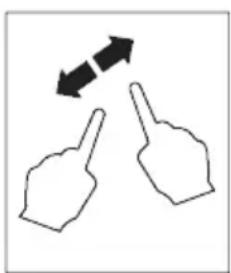
natural_image
Two hand gestures with arrows indicating bidirectional movement (no text or symbols)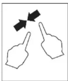
natural_image
Two hand gestures with arrows indicating movement or direction (no text or symbols)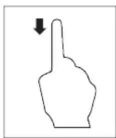
natural_image
Simple line drawing of a hand pointing upward with a downward arrow (no text or symbols)
natural_image
Simple line drawing of a hand pointing upward with an arrow (no text or symbols)natural_image
Thermal image showing heat distribution with warm yellow-orange core and cooler purple walls (no text or symbols)
natural_image
Thermal imaging view of a heat exchanger or cooling unit with visible heat flow lines (no text or symbols)text_image
C:21.8 22.9 14.5 MANUALtext_image
C:36.8 Below alarm 25.0 H 46.8 H 26.2
text_image
C:36.8 Above alarm 40.0 H 46.8 26.213.2 Paramètres
text_image
C:28.8 Parameters 42.7 08.50 A 27.2text_image
C:36.8 H 46.8 Ambient temperature 25.0text_image
C:36.8 H:46.8 Reflection temperature < 25.0 >text_image
C:36.8 H 46.8 Atmospheric Humidity < 60% >text_image
C:36.8 Infrared compensation < 0.0 > H 46.8text_image
C:36.8 H 46.8 distance 2.0text_image
C:36.8 H 46.8 Emissivity < 0.95 > E↑text_image
C:36.8 H 46.8 Measurement 26.2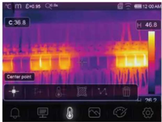
text_image
C:36.8 H 46.8 Center point 26.2text_image
C:28.8 A 42.8 Iron
Radioactif marron
text_image
C:31.4 H 32.9 H 27.1 HG HI:30.0
text_image
C:36.8 H 46.8 Thermal 26.2Thermique
text_image
C:36.8 Picture in picture 68% Fusiontext_image
C:36.8 Camera H 46.8 26.2O Caméra
text_image
C:36.8 46.8 26.2
text_image
C:36.8 H 46.8 H 26.2text_image
Technical diagram of a handheld device with numbered parts labeled 1 to 5
text_image
6 7 8 9 10 4natural_image
Simple line drawing of a hand with a finger pressing a button (no text or symbols)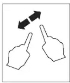
natural_image
Two hand gestures with bidirectional arrows indicating movement (no text or symbols)
natural_image
Two hand gestures with arrows pointing at each (no text or symbols)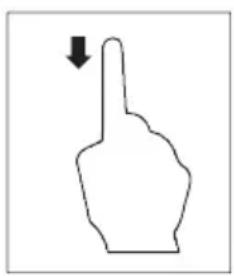
natural_image
Simple line drawing of a hand pointing upward with a downward arrow (no text or symbols)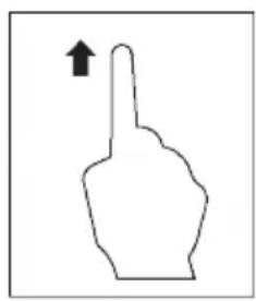
natural_image
Simple line drawing of a hand pointing upward with an arrow (no text or symbols)natural_image
Thermal imaging comparison showing heat transfer from a device to a heat sink (no text or symbols visible)text_image
C:21.8 22.9 14.5 MANUALtext_image
C:36.8 Below alarm 25.0 H 46.8 H 26.2
text_image
Above alarm 40.013.2 Parameters

text_image
C:28.8 Parameters 42.7 27.2 08 50 °C m ε =0.95 Atext_image
C:36.8 H 46.8 Ambient temperature < 25.0 >text_image
C:36.8 H 46.8 Atmospheric Humidity < 60% >text_image
C:36.8 Infrared compensation < 0.0 > H 46.8text_image
C:36.8 H 46.8 distance 2.0text_image
C:36.8 H 46.8 Emissivity < 0.95 > E↑text_image
C:36.8 H 46.8 Measurement 26.2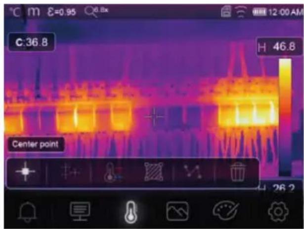
text_image
C:36.8 H 46.8 Center point 26.2De meetinstellingen openen: Menu → Measurement (Meting).
text_image
C:28.8 A 42.8 Iron


text_image
C:31.8 HI:32.9 Lo:29.9 A 35.6 A 28.2 AUTOZichtbare zone
text_image
C:36.8 H 46.8 Thermal 26.2Thermisch
13.5.2 Picture-in-picture

text_image
C:36.8 Picture in picture < 68% > Fusion H 46.8 26.2Picture-in-picture
text_image
C:36.8 H 46.8 Camera 26.2Camera
text_image
C:36.8 H 46.8 26.2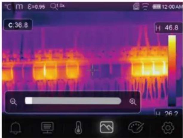
text_image
C:36.8 H 46.8 H 26.2This is a publication by Conrad Electronic SE, Klaus-Conrad-Str. 1, D-92240 Hirschau (www.conrad.com).
All rights including translation reserved. Reproduction by any method (e.g. photocopying, microfilming or the capture in electronic data processing systems) requires prior written approval from the editor. Reprinting, also in part, is prohibited. This publication reflects the technical status at the time of printing.
Copyright by Conrad Electronic SE *2890410, 2890411, 2890412_V3_0424_dh_mh_en 27021598914592523-2 l4/O3 en