Gysduction Auto Meca + - Cooker GYS - Free user manual and instructions
Find the device manual for free Gysduction Auto Meca + GYS in PDF.

User questions about Gysduction Auto Meca + GYS
0 question about this device. Answer the ones you know or ask your own.
Ask a new question about this device
Download the instructions for your Cooker in PDF format for free! Find your manual Gysduction Auto Meca + - GYS and take your electronic device back in hand. On this page are published all the documents necessary for the use of your device. Gysduction Auto Meca + by GYS.
USER MANUAL Gysduction Auto Meca + GYS
natural_image
Line drawing of a vintage electronic device with ports and buttons (no text or symbols)FR 1-12 / 78-80
EN 13-22 / 78-80
DE 23-33 / 78-80
ES 34-44 / 78-80
RU 45-55 / 78-80
NL 56-66 / 78-80
IT 67-77 / 78-80
GYSDUCTION AUTO
INSTRUCTIONS DE SÉCURI TÉ
natural_image
Diagram of a device casing with labeled components and a circular pattern (no text or symbols)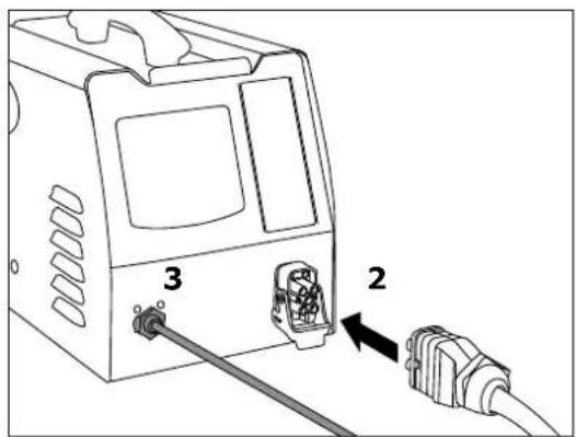
natural_image
Close-up of a black cable with a connector and two pins (no text or symbols visible)
Description
natural_image
Diagram of a car interior showing airflow and structural components (no text or symbols)
natural_image
Diagram of a car's front and side compartments showing airflow or ventilation (no text or symbols)natural_image
Coiled black cable with connector pin (no text or symbols visible)
Description
natural_image
Pure mechanical part diagram showing a T-shaped component and a hexagonal nut (no text or symbols)natural_image
Coiled black cable with a white and black band, next to a rectangular device (no text or symbols visible)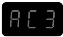
Description
natural_image
Line drawing of a car interior with a partially open air conditioner cover and a striped blanket (no text or symbols)natural_image
Coiled black cable with two connectors, no visible text or symbols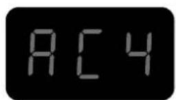
Description
natural_image
Line drawing of a hand holding a tool with a cable, no text or symbols present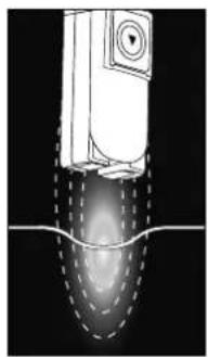
natural_image
Diagram of a mechanical device with internal flow lines and a central component (no text or symbols)
natural_image
Coiled black electrical plug with two connectors (no text or symbols visible)
Description
natural_image
Technical line drawing of a mechanical assembly showing a shaft and housing with a directional arrow indicating motion (no text or symbols)
CONDITIONS DE GARANTIE
This manual contains safety and operating instructions, to be followed for your safety. Please read it carefully before using the device for the first time and keep it in a safe place for future reference. Read and understand the following safety recommendations before using or servicing the unit. Any change or servicing that is not specified in the instruction manual must not be undertaken. The manufacturer is not liable for any injury or damage caused due to non-compliance with the instructions featured in this manual. If there is any issue or uncertainty, please consult a qualified individual to operate the equipment correctly. This machine may only be used to heat ferrous materials within the limits indicated on the equipment and manual. The operator must observe the safety precautions. In case of inedaquate or unsafe use, the manufacturer cannot be held liable for damage or injury. Any other uses not specified in this manual is forbidden, and possibly dangerous. The product is semi automatic and requires the presence of an operator.
This unit can be used by children aged 8 or over and by people with reduced physical, sensory or mental capabilities or lack of experience or knowledge, if they are properly monitored or if instructions for using the equipment safely have been read and risks made aware of. Children must not play with the product. Cleaning and maintenance should not be performed by an unsupervised child.
Do not use the charger if the mains cable or plug is damaged.
Do not cover the device.
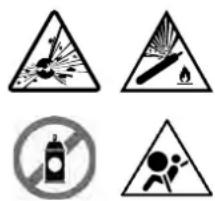
Fire and explosion risks!
- Do not use the device in an explosive atmosphere.
- Keep gas cannisters or other pressurised gas containers away from the induction heating machine.
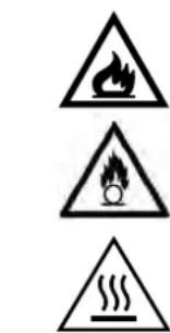
Warning, heat and flame risk.
- Do not overheat parts and adhesives.
- Be wary of fire, keep a fire extinguisher is in the vicinity..
- Do not position the machine on, or near flammable surfaces.
- Do not position the machine near flammable materials.
Warning! Very hot surface. Risk of burns.
- The parts and pieces that have just been heated are hot and may cause burns when manipulated.
- Do not touch any hot parts with your hands.
- Wait for the parts and pieces to cool down before handling them.
- Check that jewellery (such as wedding rings) or other metal pieces do not get close to the induction heating machine or the inductor when switched on.
- Remove any jewellery or any metal object from yourself before using this machine
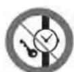
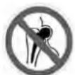
- People with metal implants should not use this machine.
- In case of burns, rinse with water abundantly and see a medi- cal doctor as soon as possible.
Dangerosity of the gas fumes
- Keep the head away from the fumes, do not inhale.
- If working inside, ventilate the area or use a fume extractor to evacuate the gases and fumes.
- Induction heating of certain materials such as adhesives and flux can generate fumes and gases. Breathing these fumes and gases can be dangerous for your health. For example, heating urethane generates a gas: hydrogen cyanide, potentially mortal for humans.
- If the ventilation is insufficient, use an approved respiratory unit.
- Read the safety data sheets (MSDS) and the manufacturer's instructions for adhesives, flux, metals, consumables, coatings, cleaning agents, corrosives, and paint strippers.
- Do not use the heater on parts being degreased or sprayed. The heat might react with fumes and generate highly toxic gases.
- Work in a confined area only if it's well ventilated, or use an approved respiratory/filtration unit. Make sure that a qualified person is around to watch over you. The fumes and gases released while heating can replace oxygen or air, causing accidents or death. Check the quality of the air you're breathing
- Do not overheat metals, such as galvanised steel, covered with lead or cadmium, unless the coating is removed from the surface before it's heated, that the area is well ventilated, and if needed, use an approved filtration/respiratory unit.. Foundry pieces and all metals containing such elements may generate toxic fumes if overheated. Check the MSDS for temperature related details.
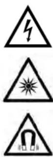
Warning, electrical danger
Caution: Danger of optical radiation when the heated metal elements reach fusion.
Warning ! Major magnetic field. People wearing active or passive implants must be informed.
No further protective steps are required when the machine is used on its own. Further restrictions and/or protective measures may be necessary in other cases
After maintenance, the magnetic field levels must be checked before the machine is used again.
When switched on, never put the inductor near the head or vital organs.
People wearing pacemakers are advised to not come close to the machine. Risk of disruption of pacemaker operations when close to the machine. Consult a doctor before getting close to induction heaters.
Risk of metal or adhesive projections
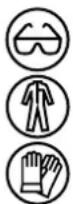
- Wear approved protective goggles with lateral protections, or protect the whole face with a screen.
- Wear protective clothes.
- Wear gloves.
Do not obstruct the machine's air intake, which facilitates air circulation. Check the installation chapter before using the device.
Connection:
- This machine must be connected to an earthed socket.


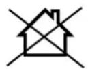
- These Class A devices are not intended to be used on a residential site where the electric current is supplied by the public network, with a low voltage power supply. There may be potential difficulties in ensuring electromagnetic compatibility on these sites, because of the interferences, as well as radio frequencies.

- This hardware is compliant with the IEC 61000-3-12.
• This equipment complies with the IEC 61000-3-11.
Maintenance:
- If the power cable is damaged, it must be replaced by the manufacturer, its after sales service or an equally qualified person to prevent danger.
-
Warning! Always disconnect from the mains before performing maintenance on the device.
• High Voltage and Currents inside the machine. -
Remove the casing on a regular basis, to remove any excess dust. Take this opportunity to have the electrical connections checked by a qualified person, with an insulated tool.
- Do not use solvents or any agressive cleaning products.
Regulations:

• Device complies with europeans directives.
- The certificate of compliance is available on our website.
• EAC Conformity marking (Eurasian Economic Community).
• Equipment in conformity with Moroccan standards.
- The declaration C_ (CMIM) of conformity is available on our website (see cover page).
Waste management:

- This product should be disposed of at an appropriate recycling facility. Do not throw away in a domestic bin.

- Equipment in compliance with British requirements. The British Declaration of Conformity is available on our website (see home page).


•This product should be recycled appropriately.
I DENTI FI CATI ON
On the back of the product is the following information:
- Manufacturer's name and address
- Model
• Product serial number - Operating voltage
- Product power
Model and serial number must be mentioned each time a technician intervention is required or if spare parts are requested.
POWER SUPPLY
The GYSDUCTION is fitted with a 16A socket type CEE7/7 which must be connected to a single-phase 230V (50/60 Hz) power supply fitted with three wires and one earthed neutral.
Check that the power supply and its protection (fuse and/or circuit breaker) are compatible with the current needed by the machine. The product is protected for operation on a generator.
SAFETY DEVICES
- The product has the safety feature PROTEC 400. It is protected against overvoltage above 300V and against neutral disconnection.
- During intensive use, the inductor, cables, electronics and power transformer heat up. In order to avoid dysfunction due to overheating, the Gysduction is equipped with an air cooling circuit. A thermal protection also switches off the product when the internal temperature becomes too high.
- The inductors are insulated to protect the user against possible electric shock..
- The Gysduction is equipped with a safety device against accidental heating. If the heating control is inadvertently activated (pressure on the control pedal or glass inductor control button), and the inductor is not in contact with the metal to be heated for a time exceeding one minute, then the unit will beep and switch off automatically. Release the heater control to go back to a normal heating cycle.
PRODUCT DESCRIPTION
Gysduction is made up of an inductor connected to an alternating medium-frequency power source. When a heating control is switched on, a strong magnetic field is emitted by the inductor. When approaching a ferrous metal, the induced currents will create heating in the metal, without physical contact.
Gysduction Auto can be used for many applications (depending on the selected inductor):
- to remove all logos, adhesives, mouldings, plastic rods glued to bodywork.
- unbolt and unlock metal parts (bolts, screws, connecting rods...).
- remove bonded glass (rear glass, rear quarter, panoramic roof).
- Remove rubbing strips and seals.

The product will heat steel, but is not suitable for heating Aluminum, copper or zinc.
OPERATING INSTRUCTIONS
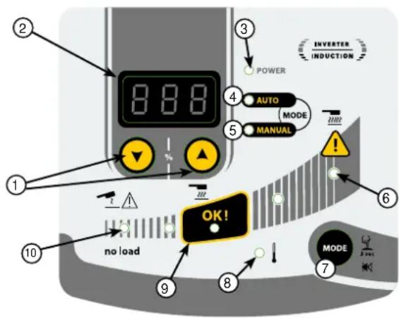
| 1 Setting controls |
| 2 Digital display |
| 3 Power-on indicator |
| 4 Auto mode indicator |
| 5 Manual mode indicator |
| 6 Max. power indicator |
| 7 Selection mode button |
| 8 Thermal protection indicator |
| 9 Optimal heating area |
| 10 «No load» indicator |
No-Load If there is no part to be heated, or if the inductor is placed on a non-ferrous
metal, the « no-load »indicator (10) lights up when pressure is applied on one of the heating controls.
Automatic mode
To start this mode:
With this mode, Gysduction adapts to suit the part to be heated (size-thickness) and takes into account the distance between the part and the inductor. It maintains a constant and optimal heating power, symbolised by the OK zone (9) of the interface. With this mode, the GYSduction never heats at maximum power.
Automatic mode is the default heating mode. If, however, the unit is set to manual mode, briefly press the MODE button (7) until the LED in front of "AUTO" (4) lights up.
Display :
The digital display shows the last \% value used by the machine to maintain a constant and optimal power according to the heating conditions. This value corresponds to the settings that should be used in Manual mode to obtain the same result with the same conditions. Thus, if the user considers the heating recommended by the Gysduction too low or too high, he can copy this value in the manual mode and vary it to reach the desired power.
Manual mode In this mode, the user selects the desired heating power.
To start this mode: Briefly press the MODE button (7) until the LED in front of « MANUAL » (5) lights up.
Operating : The digital display (2) shows the percentage of the maximum power (2400 W) that the inductor can transmit to the workpiece to be heated. Use the setting buttons (1) to adjust to the desired power.

The manual mode allows to reach the maximum power of the Gysduction. At this power, workpieces can heat up very quickly. The closer the inductor is to the workpiece, the higher the heating power will be.
Audible heating signal
An audible BEEP can be activated to indicate heating activity. The BEEP sounds as soon as the heating is effective and its frequency varies according to the position of the inductor in relation to the part to be heated. The closer the inductor, the higher the frequency.
To activate/deactivate this function: Press the MODE button (7) for 3 seconds to activate/deactivate this BEEP.
Thermal protection indicator (8)
This indicator lights up to indicate that the product has entered thermal protection due to overheating. As long as this light remains on, the product is inoperative. It switches off when the product has cooled enough. Heating can only be reactivated from this point on.
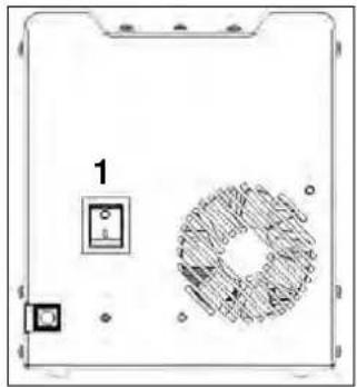
PRODUCT START UP

natural_image
Diagram of a device casing with labeled components and a circular pattern (no readable text or symbols)
Switch on the station (1)
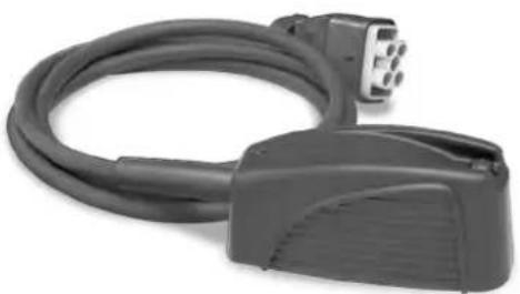
Accessory connection (2)
- Select the required inductor.
- Lift the valve on the Gysduction connector.
- Connect the inductor connector to the Gysduction.
- Close the valve to lock the connection.
- The display shows the number of the connected accessory (eg. AC1)
Connection of the control pedal (3)
The Gysduction can be supplied with a control pedal (ref. 055490), necessary for the use of the bolt, adhesive and spiral inductors. Connect the cable to the Gysduction and the pedal to make it work.
Heating activation
The glass and dent pulling inductors are fitted with a heating button. The three other ones work with the control pedal.
Bring the inductor close to the metal part to be heated, then press the inductor button or the control pedal to activate the heating.
INDUCTOR DESCRIPTION & USE

All operations described below require practice. GYS recommend experimenting by carrying out tests on sheet metal or write-off.
Glass inductor
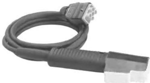
ref. 053373
natural_image
Coiled black electrical plug with a connector (no visible text or symbols)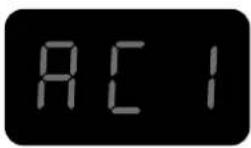
Description
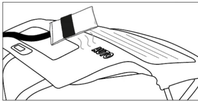
This inductor is specifically designed to strip off the anti-gravel protection from the lower part of the car body. It can also be used to remove bonded glass (rear glass, rear quarter, panoramic roof, etc.).
Automatic mode is particularly recommended for removing glass.
Removing glass
◇ Preparation
- Remove any exterior trim beforehand: For mouldings that cannot be removed, heat the bond from the inside.
- It is recommended that you also remove any interior trim and components such as clips and studs that may be used to hold the glass in place.
- Disconnect aerials and glass defrost circuits.
- Apply protective tape around the glass to prevent damage to the painted surfaces during handling.
- Apply protective tape on the glass inductor to avoid scratching the glass. Replace the adhesive tape after each glass removal.
- Thoroughly clean the glass before starting the removal process.
◇ Heating step & glass removal

The greatest risk of painting damage is at the beginning of the heat-up because of the extra difficulty of introducing shims between the glass and the body.
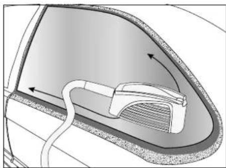
Start in a corner and heat up on each side of that corner as you progress to the opposite corners.
If the glass is damaged, start at the corner to be repaired and work your way to the undamaged part of the glass.
natural_image
Diagram of a car interior showing airflow or movement around a vehicle component (no text or symbols)
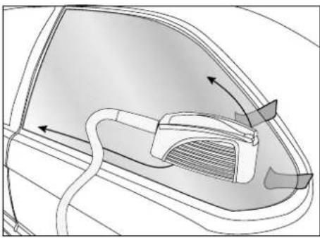
Welded edges on which the glue joints sit

Visible painted surfaces that must not be heated

Heating progress directions
7. Place the inductor opposite the urethane glue joint for easy removal from the glass.
Some vehicles have narrow welded edges, heating of the inductor can damage the visible painted surface. In that case it is advisable to cool the outer surface with a damp cloth or cooling spray. Move the inductor towards the middle of the glass so that it is at least 2 cm away from the visible painted part.
- Move the inductor back and forth about 30~cm on both adjacent sides of the corner. Finding the right heating speed: A pace that is too slow results in excessive localized heating that is inefficient because it reduces the heat produced at the welded edge. A high pace does not allow sufficient heating of the welded edge and the glue joint. A slight smoke is emitted to indicate that the optimal temperature of the urethane glue bead has been reached.
If thick smoke appears, stop heating immediately. Move away from the area to avoid breathing fumes and try to determine the cause. Heating the urethane glue causes the emission of hydrogen cyanide, which is very dangerous to ingest.
natural_image
Diagram of a car's front and rear door showing internal components with arrows indicating movement (no text or symbols)- Apply pressure from inside the vehicle without breaking the seal.
Once the seal is removed, it will not stick to the metal again.
When the glass corner lifts, slide a plastic wedge into the space left between the glass and the welded edge. Be careful not to exert too much force that could break the ice.
- Once the corner of the pane is released / peeled off, repeat the heating process along the length and height of the pane while moving the wedges under the pane as you go.
| Windows Material | Glass fragility | Removal time according to vehicle size | |
| Front windscreen Laminated glass + | ++ 20 min to 1 h | ||
| Rear window | Annealed glass + 10 to 20 min | light window | |
| Side windows |
Bolt inductor
ref. 053366
natural_image
Coiled black cable with connector port, no visible text or symbols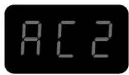
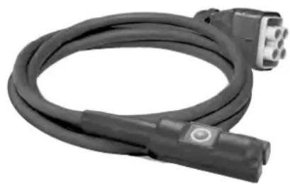
Description
The bold inductor is used for intense heating of rusted or seized parts such as nuts and bolts. This inductor can also be used for removing caulking from truck chassis or car trunks, for welding large connectors or for metal forming.
Use
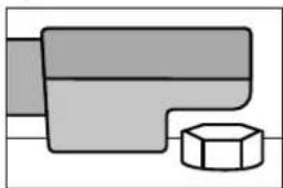
• To remove a seized or rusted nut / bolt:
natural_image
Pure mechanical component diagram without any text, numbers, or symbols- Choose Auto mode or set the power at a very high level (80 to 100% of power).
- Place the bolt inductor on the nut as shown.
- Start the heater and let it run for a few seconds.
- Loosen the nut or the bolt.
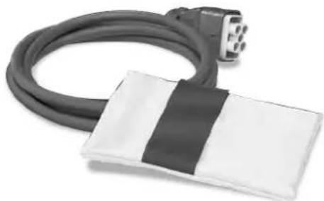
Adhesive inductor
ref. 053359
natural_image
Coiled black cable with a white rectangular patch, attached to a connector (no text or symbols visible)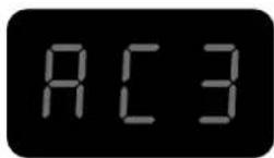
Description
This inductor is designed to peel off door mouldings / rubbing strips, badges as well as advertising and decorative adhesives in a few minutes without damage.
Use
- For heating painted metal sheets
- Select Auto mode or set the power to a low level (10 to 30% of its maximum heating capacity).
- Place the inductor just above the area to be heated. There must be no contact between the inductor and the area or element to be heated.
- While activating the heater, make a circular or to-and-fro movement on the area to be heated.

If the inductor stays too long on the same area, the paint may burn. To avoid this, it is necessary to keep the inductor constantly in motion (back and forth or circular).
- For peeling off decals, vinyl stickers or glued bars
natural_image
Line drawing of a person's seat with a credit card and ribbon, no text or symbols presentCarry out the three steps described above (see to heat the painted sheets). Heat for a few seconds and try to lift one edge of the element. If it starts to peel off easily upwards, the required temperature has been reached, otherwise continue heating for a few more seconds and try again.

Some elements that have been glued for a long time often require a longer heating time. If a sticker is overheated, it often becomes soft and puffy. If this happens, allow to cool and try again to remove and peel the sticker. Be careful not to burn the paint! If the sheet metal is heated sufficiently, the stickers should peel off easily, taking the glue with them.
- For the removal of mouldings glued to the bodywork
Body side mouldings are removed in the same manner as transfers and stickers. Higher power or longer time is required for thicker mouldings. The metal under the mouldings is further away from the inductor.
- Select Auto mode or set the power to a medium level (40 to 60% maximum heating).
- Place the inductor parallel to the work surface to achieve uniform heat distribution.
- Favour a back and forth movement along the length of the moulding. Start with one end of the moulding. Slowly move back and forth a few centimetres until the end of the moulding can be removed effortlessly.
- Then slowly move the inductor further along the molding while detaching the molding from the body.

The tape is usually removed with the moulding. If adhesive or tape remains stuck to the body, then advance more slowly or increase power.
- For heating body parts
In winter or in regions with cold climates, the body of a car to which transfers, stickers or beads are to be affixed must be preheated in the workshop to allow the adhesives to adhere.
- Set the power at low level (10 to 30% of its maximum heating capacity)
- Use circular or back and forth movements on the area to be preheated.
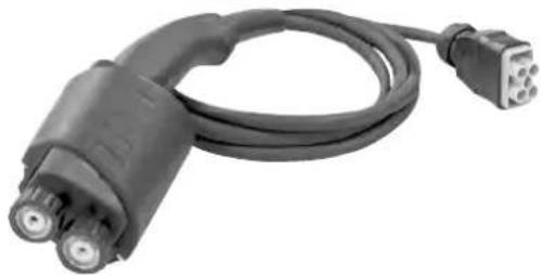
Paintless dent pulling inductor
ref. 054776
natural_image
Coiled black cable with two connectors, no visible text or symbols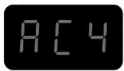
Description
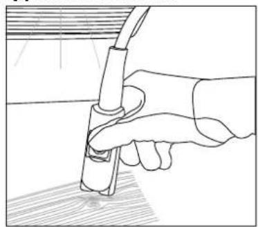
The dent pulling inductor has been designed for paintless dent repairs on car bodies, made by hail impacts for example. The heating is from the outside and the heat is very limited.
Application and use
natural_image
Line drawing of a hand holding a tool with a cable, no text or symbols present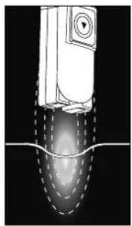
natural_image
Diagram of a mechanical component with dashed lines indicating flow or motion, no visible text or symbols
Refer to the manual supplied with the product for instructions on how to use it.
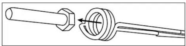
Spiral inductor
ref. 054783
natural_image
Coiled black electrical plug with two connectors (no text or symbols visible)
Description
This inductor is designed to heat and remove any mechanical part in a few seconds: e.g. seized bolts/nuts, screws...etc.
Application and use
natural_image
Technical line drawing of a mechanical assembly showing a shaft and housing with a valve mechanism (no text or symbols)
Refer to the manual supplied with the product for instructions on how to use it.
CONSUMABLES
Inductor cloths
The fibreglass cloth on the glass and de-seize inductors can wear out through use and friction against the parts to be heated. These cloths can be replaced, and GYS provides the following kit references to allow this change.
| 053854 SET OF $ GLASS INDUCTOR PROTECTIONS + GLUE |
| 053847 SET OF 10 BOLT INDUCTOR PROTECTIONS GYSDUCTION + GLUE |
| 059108 1 ADHESIVE INDUCTIVE PROTECTION + GLUE |
Cooling spray
This cooling spray is particularly useful during paintless dent removal operations and for cooling heated parts.
048898 SET OF 12 COOLING SPRAYS -50°C / 400 ml
FAULT CODES
CODE MEANING
E - 1 Pedal activated on power-up.
E - 2 Glass inductor button activated on power-up.
E - 3 Front panel ON/OFF button activated on power-up.
E - 4 Overcurrent in the inductor (either because it is very hot or because there is a short circuit).
E - 5 Defective inductor (wire cut or disconnected).
NO- ACC Accessory not connected.
AC - Accessory not recognized.
WARRANTY
The warranty covers faulty workmanship for 2 years from the date of purchase (parts and labour).
The warranty does not cover:
- Transit damage.
- Normal wear of parts (eg. : cables, clamps, etc..).
- Damages due to misuse (power supply error, dropping of equipment, disassembling).
- Environment related failures (pollution, rust, dust).
- Inductors and removable ferrites that are consumables.
- Use of unspecified coolant.
In case of failure, return the unit to your distributor together with:
- The proof of purchase (receipt etc ...)
- A description of the fault reported
natural_image
Diagram of a device casing with labeled components (no readable text or symbols)
natural_image
Coiled black cable with a connector, no visible text or symbols
Beschreibung
natural_image
Diagram of a car's side profile showing airflow or movement around the window (no text or symbols)
Klebebereiche

natural_image
Diagram of a car's rearview and side profile showing airflow or ventilation system (no text or labels)natural_image
Coiled black cable with connector pin, isolated on white background (no text or symbols)
Beschreibung
natural_image
Pure mechanical component diagram without any text, numbers, or symbolsnatural_image
Coiled black cable with a white rectangular patch, attached to a black-and-white package (no text or symbols visible)
Beschreibung
natural_image
Line drawing of a car's seat with a credit card and cable, no text or symbols presentnatural_image
Coiled black cable with two connectors, no visible text or symbols
Beschreibung
natural_image
Line drawing of a hand holding a tool with a cable, no text or symbols present
natural_image
Diagram of a mechanical device with internal components and dashed lines indicating flow or movement (no text or symbols)
natural_image
Coiled black electrical plug with two connectors and a terminal connector (no text or symbols visible)
Beschreibung
natural_image
Technical line drawing of a mechanical assembly showing a shaft and housing with a valve mechanism (no text or symbols)
natural_image
Diagram of a device casing with labeled components and a circular patterned inset (no text or symbols)
Enciende el set (1)
natural_image
Coiled black cable with a connector, no visible text or symbols
Descripción
natural_image
Diagram of a car interior showing airflow or movement around a vehicle component (no text or symbols)natural_image
Diagram of a car's front and rear door showing internal components with arrows indicating flow or movement (no text or symbols)natural_image
Coiled black cable with connector port, no visible text or symbols
Descripción
natural_image
Pure mechanical part diagram showing a T-shaped component and a hexagonal nut (no text or symbols)natural_image
Coiled black cable with a white rectangular patch, attached to a plug terminal (no text or symbols visible)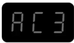
Descripción
natural_image
Line drawing of a car air conditioner with a partially visible card and label 'AUTO' (no text or symbols beyond the label)natural_image
Coiled black cable with two connectors, no visible text or symbols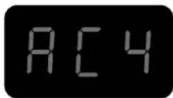
Descripción
natural_image
Line drawing of a hand holding a tool with a cable, no text or symbols present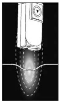
natural_image
Diagram of a mechanical component with internal flow lines and a central gradient, no text or symbols present
natural_image
Coiled black electrical plug with two connectors (no text or symbols visible)
Descripción
natural_image
Technical line drawing of a mechanical assembly showing a shaft and housing with a valve mechanism (no text or symbols)
natural_image
Diagram of a device casing with labeled components and a circular patterned inset (no text or symbols)
natural_image
Coiled black cable with a connector, no visible text or symbols
Описание
natural_image
Diagram of a car interior showing a curved roof and internal component with directional arrows (no text or symbols)
natural_image
Diagram of a car's front and side compartments showing airflow or ventilation (no text or symbols)natural_image
Coiled black cable with connector port, no visible text or symbols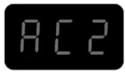
Описание
natural_image
Pure mechanical part diagram without any text, numbers, or symbolsnatural_image
Coiled black cable with a white rectangular patch, next to a small connector (no text or symbols visible)
Описание
natural_image
Line drawing of a car interior with a striped blanket and 'AUTO' label on the back panel (no readable text or symbols beyond basic markings)natural_image
Coiled black cable with two connectors, no visible text or symbols
Описание
natural_image
Line drawing of a hand holding a tool with a cable, no text or symbols present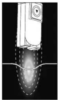
natural_image
Diagram of a mechanical device with internal components and dashed lines indicating flow or motion (no text or symbols)
natural_image
Coiled black electrical plug with two connectors (no text or symbols visible)
Описание
natural_image
Technical line drawing of a mechanical assembly showing a shaft and housing with a valve mechanism (no text or symbols)
WERKING VAN HET APPARAAT
natural_image
Diagram of a device casing with labeled components and a circular pattern (no text or symbols)
natural_image
Coiled black cable with a connector, no visible text or symbols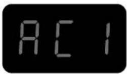
Omschrijving
natural_image
Diagram of a car interior showing airflow or movement around a component (no text or symbols)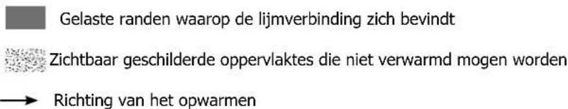
natural_image
Diagram of a car interior showing airflow or ventilation system with arrows indicating direction (no text or symbols)natural_image
Coiled black cable with connector port, no visible text or symbols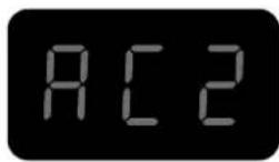
Omschrijving
natural_image
Pure mechanical part diagram showing a T-shaped component and a hexagonal nut (no text or symbols)natural_image
Coiled black cable with a white rectangular patch, next to a connector (no text or symbols visible)
Omschrijving
natural_image
Line drawing of a car air conditioner with a card and temperature label (no text or symbols beyond the label)natural_image
Coiled black cable with connector and connector port (no visible text or symbols)
Omschrijving
natural_image
Line drawing of a hand holding a tool with a cable, no text or symbols present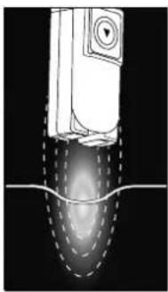
natural_image
Diagram of a mechanical component with internal flow lines and a central gradient, no text or symbols present
natural_image
Coiled black electrical plug with two connectors (no text or symbols visible)
Omschrijving
natural_image
Technical line drawing of a mechanical assembly showing a shaft and housing with a central bore (no text or symbols)
natural_image
Diagram of a device casing with labeled components and a circular patterned inset (no readable text or symbols)
natural_image
Coiled black cable with a connector, no visible text or symbols
Descrizione
natural_image
Diagram of a car interior showing airflow or fluid flow around a component (no text or symbols)
natural_image
Diagram of a car's front and side compartments showing airflow or ventilation (no text or symbols)natural_image
Coiled black cable with connector port, no visible text or symbols
Descrizione
natural_image
Pure mechanical part diagram showing a T-shaped component and a hexagonal nut (no text or symbols)natural_image
Coiled black cable with a white rectangular patch, next to a connector (no text or symbols visible)
Descrizione
natural_image
Line drawing of a car interior with a partially open air conditioner cover and a striped blanket (no text or symbols)natural_image
Coiled black cable with two connectors, no visible text or symbols
Descrizione
natural_image
Line drawing of a hand holding a tool with a cable, no text or symbols present
natural_image
Diagram of a mechanical device with internal components and flow lines (no text or symbols)
natural_image
Coiled black electrical plug with two connectors (no text or symbols visible)
Descrizione
natural_image
Technical line drawing of a mechanical assembly showing a shaft and housing with a valve mechanism (no text or symbols)
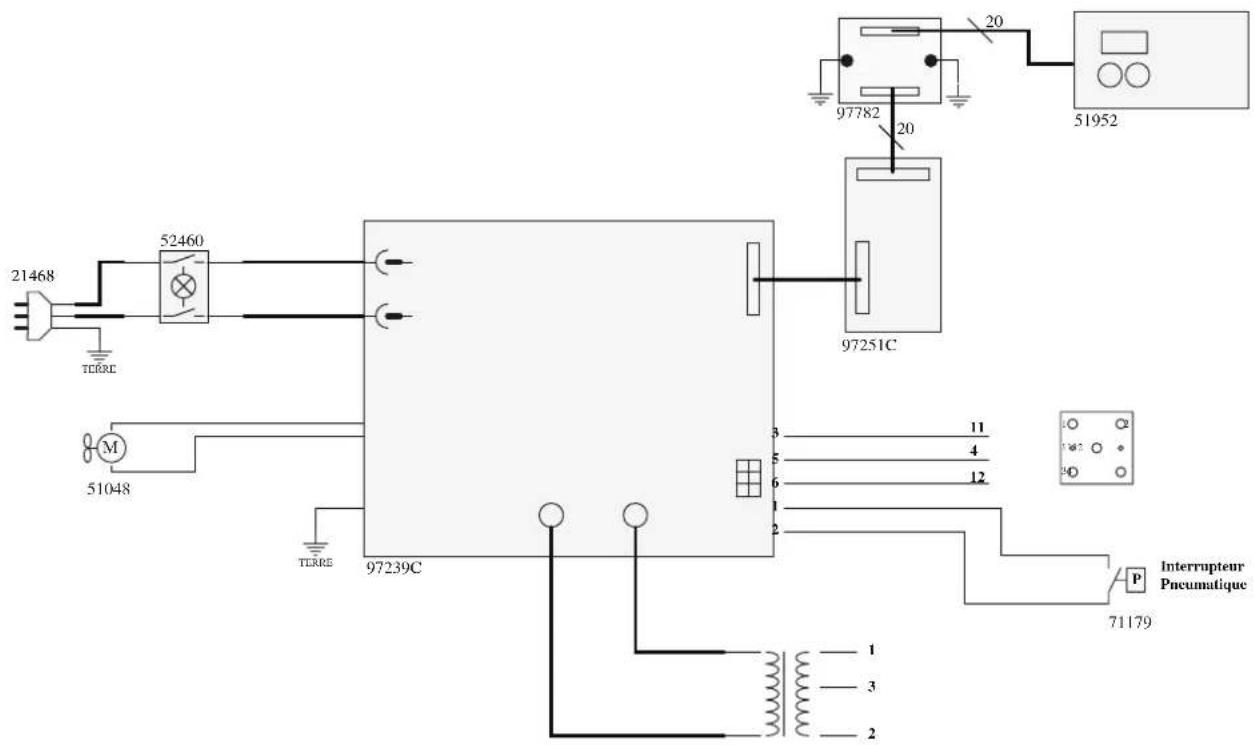
| 1 | Clavier / Keypad / Bedienfeld / Teclado / Панель управления / Bedieningspaneel / Tastiera | 51952IndX |
| 2 | Ventilateur / Fan / Ventilator / Ventilador / Вентилятор / Ventilator / Ventilatore | 51048 |
| 3 | Connecteur pneumatique / Pneumatic connector / Pneumatischer Anschluss / Conector neu-mático / Пневматический соединитель / Pneumatische aansluiting / Connettore pneuma-tico | 71179 |
| 4 | Connecteur pour inducteur / Connector for inductor / Anschluss für Induktor / Conector parainductor / Разъем для индуктора / Aansluiting inductor / Connettore per induttore | S91534 |
| 5 | Circuit de commande / Control circuit / Mikrokontrollerplatine / Circuito de commando / Платауправления / Besturingscircuit / Circuito di comando | Si fab < 21.03 : S97251Si fab = 21.03 : Consulter SAVSi fab > 21.03 : 97251C |
| 6 | Circuit adaptation interface clavier / Keyboard interface adaptation circuit / Schaltung zurAnpassung der Tastaturschnittstelle / Circuito de adaptación de la interfaz del teclado / Схемаадаптации интерфейса клавиатуры / Toetsenbordinterface aanpassingscircuit / Circuito diadattamento dell'interfaccia della tastiera | 97782C |
| 7 | Carte électronique / Circuit board / Platine / Tarjeta electrónica / Электронная плата / Print-plaat / Scheda elettrica | 97239C |
| 8 | Interrupeur marche/arrêt / ON/OFF switch / Ein/Aus Schalter / Interruptor encendido/apagado / Прерыватель ВКЛ/ВЫКЛ / Aan/uit knop / Interruttore avvio/arresto | 52460 |
| 9 | Cordon secteur / Power supply cable / Netzleitung / Cable de conexión eléctrica / Сетевойшнур / Netsnoer / Cavo corrente | 21468 |
| 10 | Transformateur / Transformer / Transformator / Transformador / Transformator / Trasforma-tore | 96100 |
| 11 | Poignée / Handle / Handgriff / Mango / Handvat / Impugnatura | 56047 |
SPECIFICATIONS / SPECIFICATIONS / TECHNISCHE DATEN / ESPECIFICACIONES / TEXНИЧЕСКИЕ ХАРАКТЕРИСТИКИ / SPECIFICATIES / SPECIFICHE
| GYSDUCTI ON AUTO | |
| Puissance / Power / Leistung / Potencia / Мощность / Vermogen / Potenza | 2.4 kW |
| Fréquence tension secteur / Mains voltage frequency / Frequenz der Netzspannung / Frecuencia del voltaje de la red / Частота напряжения сети / Frequentie netspanning / Frequenza di tensione rete | 50-60 Hz |
| Tension d'utilisation / Voltage in use / Betriebsspannung / Tensión de uso / Напряжение использования / Bedrijfsspanning / Tensione d'utilizzo | 165-240 V |
| Fréquence du réchauffeur / Heater frequency / Frequenz des Vorwärmers / Frecuencia del calentador / Частота нагрева / Frequenza del riscaldatore / Frequentie verwarmingselement / Frequenza del riscaldatore | 35-120 kHz |
| Longueur câble secteur / Mains cable length / Länge der Netzleitung / Longitud del cable eléctrico / Длина сетевого шнура / Lengte voedingskabel / Lunghezza cavo rete | 2 m |
| Longueur câble inducteur / Inductor cable length / Länge des Induktorkabels / Longitud de cable del inductor / Длина кабеля индуктора / Lengte inductiekabel / Lunghezza cavo induttore | 2 m |
| Tuyau poire de commande / Control pedal pipe / Schlauchlänge des Fernreglers / Conducto del accionador pera / Шланг дистанционного управления / Slangetje besturingsblaasbalg / Tubo pedale di comando | 2.5 m |
| Indice de protection / Protection rating / Schutzart / Índice de protección / Степень защиты / Beschermingsklasse / Indice di protezione | IP 21 |
| Poids générateur / Generator weight / Gewicht der Stromquelle / Peso del generador / вес (кг) / Gewicht generator / Peso generatore | 7.5 kg |
| Dimensions / Dimensions / Abmessungen / Dimensiones / Габариты / Afmetingen / Dimensioni | 36 x 27 x 22 cm |
SCHÉMA ÉLECTRIQUE / ELECTRICAL DIAGRAM / SCHALTPLAN / ESQUEMA ELÉCTRICO / ЭЛЕКТРИЧЕСКАЯ
CXEMA / ELEKTRISCH SCHEMA / SCHEMA ELETTRICO
ICÔNES / ICONOS / ICONEN / ICONE
 | - Attention ! Lire le manuel d'instruction avant utilisation.- Caution ! Read the user manual.- Vorsicht! Lesen Sie vor der Anwendung die Gebrauchsanweisung.- iAtención! Lea el manual de instrucciones antes de usar.- Waarschuwing ! Lees voor gebruik de handleiding.- Attenzione! Leggere il manuale di istruzioni prima dell'uso. | |
 | - Marque de conformité EAC (Communauté économique Eurasienne).- Conformity mark EAC (Eurasian Economic Commission).- EAC-Konformitätszeichen (Eurasische Wirtschaftsgemeinschaft).- Marca de conformidad EAC (Comunidad económica euroasiática).- Маркировка соответствия EAC (Евразийское экономическое сообщество).- Marchio conformità EAC (Commissione economica eurasiatica).- EAC (Éuraziatische Economische Gemeenschap) merkteken van overeenstemming | |
 | - Matériel conforme aux exigences britanniques. La déclaration de conformité britannique est disponible sur notre site (voir à la page de couverture).- Equipment in compliance with British requirements. The British Declaration of Conformity is available on our website (see home page).- Das Gerät entspricht den britischen Richtlinien und Normen. Die Konformitätserklärung für Grossbritannien ist auf unserer Internetseite verfügbar (siehe Titelseite).- Equipo conforme a los requisitos británicos. La Declaración de Conformidad Británica está disponible en nuestra página web (véase la portada).- Материал соответствует требованиям Великобритании. Заявление о соответствии для Великобритании доступно на нашем веб- сайте (см. главную страницу).- Materiaal conform aan de Britse eisen. De Britse verklaring van overeenkomt is beschikbaar op onze website (zie omslagpagina).- Materiale conforme alla esigenze britanniche. La dichiarazione di conformità britannica è disponibile sul nostro sito (vedere pagina di copertina). | |
 | - CMIM : Certification Marocaine- CMIM : Moroccan Certification- CMIM : Marokkanische Zertifizierung- CMIM : Certificación Marroquí | - CMIM : Марокканская сертификация- CMIM : Marokkaanse certificering- CMIM : Certificazione Marocchina |
 | - Apparell conforme aux directives européennes. La déclaration de conformité est disponible sur notre site Internet (www.gys.fr)- Devicecompliant with European directives. The certificate of compliance is available on our website (www.gys-welding.com)- Gerät entspricht den europäischen Richtlinien. Die Entsprechenserklärung ist auf unserer Website (www.gys.fr) verfügbar.- El aparato cumple con las directivas europeas. La declaración de conformidad está disponible en nuestra página web (www.gys.fr)- Dit apparaat is vervaardigd in overeenstemming met de eisen van de Europese regelgeving. De verklaring van overeenstemming is beschikbaar op onze internet site (www.gys-welding.com)- Il dispositivo è conforme alle direttive europee. La dichiarazione di conformità è disponibile sul nostro sito web (www.gys.fr). | |
 | - Produit recyclable qui relève d'une consigne de tri selon le décret n°2014-1577.- This product should be recycled appropriately.- Dieses Produkt sollte entsprechend recycelt werden.- Producto reciclable que está sujeto a una instrucción de clasificación según el decreto n°2014-1577.- Apparaat kan gerecycled worden, niet weggoolen met het huishoudelijk afval.- Questo prodotto deve essere riciclato in modo appropriato. | |
 | - Source de courant de technologie onduleur délivrant un courant alternatif.- Undulating current technology based source delivering alternating curent.- Inverterwechselstromquelle.- Fuente de corriente de tecnología ondulador que libera corriente continua.- Источник тока инверторной технологии, вырабатывающий переменный ток.- Stroombron wisselstroom- Fonte di corrente con tecnologia inverter che rilascia una corrente alternata. | |
 | - Alimentación eléctrica monofásica 50 o 60Hz- Single phase power supply 50 or 60 Hz- Einphasige Netzversorgung mit 50 oder 60Hz- Alimentación eléctrica monofásica 50 o 60Hz- Однофазное электропитание 50 или 60Гц- Enkelfase elektrische voeding 50 of 60 Hz- Alimentazione elettrica monofase 50 o 60Hz | |
 | N'est pas prévu pour un emploi en site résidentiel où le courant électrique est fourni par le réseau public d'alimentation basse tension (non classe B) / Not Intended to be used on a residential site where the electric current is supplied by the public network, with a low voltage power supply (not class B). / Dieses Gerät ist nicht für den Einsatz in Wohngebieten bestimmt, in denen die lokale Stromversorgung über das öffentliche Niederspannungsnetz geregelt wird. / No está previsto para uso residencial donde la corriente eléctrica es suministrada por la red pública de baja tensión (no de clase B) / Это оборудование не подходit для использования в жилых кварталах, где электрический ток подается общественной системой питания низкого напряжения (не класса B). / Niet bestemd voor gebruik in een woonomgeving waar de elektrische stroom aangeleverd wordt door een openbaar laagspanningsnet (niet klasse B). / Non è adatto ad un impiego in sito residenziale in cui la corrente elettricaviene fornita dalla rete pubblica d'alimentazione a bassa tensione (non classe B) | |