
PowerShareX PSX2404D - Receiver BOSE - Free user manual and instructions
Find the device manual for free PowerShareX PSX2404D BOSE in PDF.

| Product Type | Adaptive Power Amplifier |
| Brand | Bose |
| Model | PowerShareX PSX2404D |
| Output Power | 4 × 600 W (all configurations) |
| Dimensions (H × W × D) | 44.5 mm × 483.0 mm × 358.0 mm (1U rack) |
| Net Weight | 7.0 kg |
| Power Supply | 100-240 V ~ 50/60 Hz, 600 W max |
| Operating Temperature Range | 0 °C to 35 °C |
| Storage Humidity | 10% to 85% |
| Audio Inputs | 4 balanced analog inputs (12-pin Euroblock), 4 Dante streams via RJ45 |
| Speaker Outputs | 4 outputs, 8-pin Euroblock, configurable Lo-Z (2-8 Ω) or Hi-Z (70/100 V) |
| Control and Monitoring | Ethernet (ControlSpace Designer), GPI/Remote, GPO alarm |
| Protection | Channel limiter, thermal protection, breaker protection (BRK SAVE), power limiter |
| Cooling | Variable speed fans, front-to-back airflow, removable filter |
| Rack Mounting | 1U, 35.8 cm depth from front rail, mounting brackets included |
| Energy Saving | NRG SAVE (auto standby after 30 min without signal) |
| Configuration Software | ControlSpace Designer (download at BoseProfessional.com) |
| Included Accessories | Power cord, 4-pin, 8-pin, and 12-pin Euroblock connectors (3 pieces) |
| Warranty | Limited warranty (see BoseProfessional.com/Warranty) |
| Maintenance and Cleaning | Dry cloth; air filter washable with clean water (dry before reinstalling) |
| Safety | Grounding required, professional installation, do not open |
Frequently Asked Questions - PowerShareX PSX2404D BOSE
User questions about PowerShareX PSX2404D BOSE
0 question about this device. Answer the ones you know or ask your own.
Ask a new question about this device
Download the instructions for your Receiver in PDF format for free! Find your manual PowerShareX PSX2404D - BOSE and take your electronic device back in hand. On this page are published all the documents necessary for the use of your device. PowerShareX PSX2404D by BOSE.
USER MANUAL PowerShareX PSX2404D BOSE
| PowerShareX\PowerShareX\PowerShareX\PowerShareX\PowerShareX\PowerShareX\PowerShareX\PowerShareX\PowerShareX\PowerShareX\PowerShareX\PowerShareX\PowerShareX\PowerShareX\PowerShareX\PowerShareX\PowerShareX\PowerShareX\PowerShareX\PowerShareX\PowerShareX\PowerShareX\PowerShareX\PowerShareX\PowerShareX\PowerShareX \ PowerShareX\ PowerShareX\ PowerShareX\ PowerShareX\ PowerShareX\ PowerShareX\ PowerShareX\ PowerShareX\ PowerShareX\ PowerShareX\ PowerShareX\ PowerShareX\ PowerShareX\ PowerShareX\ PowerShareX\ PowerShareX\ PowerShareX\ PowerShareX\ PowerShareX\ PowerShareX\ PowerShareX\ PowerShareX\ PowerShareX\ PowerShareX\ PowerShareX\ PowerShareX \ PowerShareX\ PowerShareX\ PowerShareX\ PowerShareX\ PowerShareX\ PowerShareX\ PowerShareX\ PowerShareX\ PowerShareX\ PowerShareX\ PowerShareX\ PowerShareX\ PowerShareX\ PowerShareX\ PowerShareX\ PowerShareX\ PowerShareX\ PowerShareX\ PowerShareX\ PowerShareX\ PowerShareX\ PowerShareX\ PowerShareX\ PowerShareX\ P5X1204D \ P5X2404D \ P5X4804D \ | |
| PowerShareX\PowerShareX\PowerShareX\PowerShareX\PowerShareX\PowerShareX\PowerShareX\PowerShareX\PowerShareX\PowerShareX\PowerShareX\PowerShareX\PowerShareX\PowerShareX\PowerShareX\PowerShareX\PowerShareX\PowerShareX\PowerShareX\PowerShareX\PowerShareX\PowerShareX\PowerShareX\PowerShareX\Power ShareX\ PowerShareX\ PowerShareX\ PowerShareX\ PowerShareX\ PowerShareX\ PowerShareX\ PowerShareX\ PowerShareX\ PowerShareX\ PowerShareX\ PowerShareX\ PowerShareX\ PowerShareX\ PowerShareX\ PowerShareX\ PowerShareX\ PowerShareX\ PowerShareX\ PowerShareX\ PowerShareX\ PowerShareX\ PowerShareX\ PowerShareX\ PowerShareX\ Power ShareX\ PowerShareX\ PowerShareX\ PowerShareX\ PowerShareX\ PowerShareX\ PowerShareX\ PowerShareX\ PowerShareX\ PowerShareX\ PowerShareX\ PowerShareX\ PowerShareX\ PowerShareX\ PowerShareX\ PowerShareX\ PowerShareX\ PowerShareX\ PowerShareX\ PowerShareX\ PowerShareX\ PowerShareX\ PowerShareX\ PowerShareX\ PowerShareX\ P5X4804D \ P5X4804D \ P5X4804D \ P5X4804D \ P5X4804D \ P5X4804D \ P5X4804D \ P5X4804D \ P5X4804D \ P5X4804D \ P5X4804D \ P5X4804D \ |
PowerShareX
Adaptable Power Amplifiers
PSX1204D
PSX2404D
PSX4804D
Installation Guide....2
Please read and keep all safety and use instructions.
This product is intended for installation by professional installers only! This document is intended to provide
professional installers with basic installation and safety guidelines for this product in typical fixed-installation systems. Please read this document and all safety warnings before attempting installation.
-
Read these instructions.
-
Keep these instructions.
-
Heed all warnings.
-
Follow all instructions.
-
Do not use this apparatus near water.
-
Clean only with a dry cloth.
-
Do not block any ventilation openings. Install in accordance with the manufacturer's instructions.
-
Do not install near any heat sources such as radiators, heat registers, stoves, or other apparatus (including amplifiers) that produce heat.
-
Do not defeat the safety purpose of the polarized or grounding-type plug. A polarized plug has two blades with one wider than the other. A grounding type plug has two blades and a third grounding prong. The wide blade or the third prong are provided for your safety. If the provided plug does not fit into your outlet, consult an electrician for replacement of the obsolete outlet.
-
Protect the power cord from being walked on or pinched particularly at plugs, convenience receptacles, and the point where they exit from the apparatus.
-
Only use attachments/accessories specified by the manufacturer.
-
Use only with the cart, stand, tripod, bracket, or table specified by the manufacturer, or sold with the apparatus. When a cart is used, use caution when moving the cart/aoparatus combination to avoid injury from tip-over.
-
Unplug this apparatus during lightning storms or when unused for long periods of time.
-
Refer all servicing to qualified personnel. Servicing is required when the apparatus has been damaged in any way, such as power-supply cord or plug is damaged, liquid has been spilled or objects have fallen into the apparatus, the apparatus has been exposed to rain or moisture, does not operate normally, or has been dropped.
These symbols on the product mean the following:

This symbol on the product means there are important operating and maintenance instructions in this guide.

This symbol on the product means there is uninsulated, dangerous voltage within the product enclosure that may present a risk of electrical shock.

This symbol on the product means earth/ground connection.


To reduce the risk of electric shock, do not remove cover (or back). No user-serviceable parts inside. Refer servicing to qualified personnel.

WARNINGS/CAUTIONS

Contains small parts which may be a choking hazard. Not suitable for children under age 3.


This product contains magnetic material. Consult your physician on whether this might affect your implantable medical device.
- All Bose Professional products must be installed in accordance with local, state, federal and industry regulations. It is the installer's responsibility to ensure installation of the loudspeakers and mounting system is performed in accordance with all applicable codes, including local building codes and regulations. Consult the local authority having jurisdiction before installing this product.
- Do not expose this product to dripping or splashing, and do not place objects filled with liquids, such as vases, on or near the product.
• To reduce the risk of fire or electrical shock, do not expose this product to rain, liquids, or moisture.
- Keep the product away from fire and heat sources. Do not place naked flame sources, such as lighted candles, on or near the product.
- Do not make unauthorized alterations to this product.
- Provide an earth connection or ensure the socket outlet incorporates a protective earthing connection before connecting the plug to the mains socket outlet.
Dansk: Apparalets stikprop skal ülsluttes en stikkontakt med jord, som giver forbindelse til stikproppens jord. Suomi: Laite on liitettävä suojamaadoituskoskettimilla varustettuun pistorasiaan.
- Where the mains plug or an appliance coupler is used as the disconnect device, the disconnect device shall remain readily operable.
- Only use the mounting hardware recommended by the rack manufacturer.
- Only use attachments/accessories specified by the manufacturer.
- Avoid touching uninsulated wiring or wiring terminals. This product's audio wiring terminals carry voltage that can result in discomfort upon contact.
• This product is for indoor use only.
- To reduce the risk of electric shock, do not attempt to open any part of the unit. No user-serviceable parts inside. Refer servicing to qualified service personnel.
- Connection to the mains shall be done only by an electrotechnical skilled person according to the national requirements of the countries where the unit is sold.
- Do not use this amplifier if the electrical power cord is frayed or broken.
• To avoid electrical shock, do not touch any exposed speaker wiring while the amplifier is operating.
- Do not spill water or other liquids into or on the amplifier.
- The device must be powered exclusively by earth connected mains sockets in electrical networks compliant to IEC 364 or similar rules.
- Disconnect the AC mains source before attempting to clean any part of the amplifier.
- Bose Professional recommends plugging the amplifier to a 16 A-rated socket outlet, C or D curve, 10 kA sectioning breaker.
- Output terminals are hazardous: Wiring connection to these terminals requires installation by an instructed person and the use of ready-made leads.
- Properly fit the AC mains plug to the amplifier inlet. Before powering this amplifier, verify that the correct voltage rating is being used.
• Take care to lock the output terminal before switching the device on.
- Verify that your mains connection is capable of satisfying the power ratings of the device.
- No naked flame sources such as lighted candles should be placed on the amplifier.
• The testing signals might cause loudspeaker impairments.
• To prevent injury, this apparatus must be securely rack mounted in accordance with the installation instructions.
- This equipment shall be mounted at a maximum height of two meters.
- The manufacturer cannot be held responsible for damages caused to persons, things, or data due to an improper or missing ground connection.
- It is absolutely necessary to verify these fundamental requirements of safety and, in case of doubt, require an accurate check by qualified personnel.
Product Ratings
Input Voltage Frequency Current or Power
PSX1204D: 100-240 V 50/60 Hz 600 W
PSX2404D: 100-240 V 50/60 Hz 600 W
PSX4804D: 100-240 V 50/60 Hz 1100 W
Regulatory Information
CAN ICES-3 (A)/NMB-3(A)
This device complies with part 15 of the FCC Rules. Operation is subject to the following two conditions: (1) This device may not cause harmful interference, and (2) this device must accept any interference received, including interference that may cause undesired operation.
NOTE: This equipment has been tested and found to comply with the limits for a Class A digital device, pursuant to part 15 of the FCC Rules. These limits are designed to provide reasonable protection against harmful interference when the equipment is operated in a commercial environment. This equipment generates, uses, and can radiate radio frequency energy and, if not installed and used in accordance with the instruction manual, may cause harmful interference to radio communications. Operation of this equipment in a residential area is likely to cause harmful interference in which case the user will be required to correct the interference at their own expense.
Changes or modifications not expressly approved by Bose Professional could void the user's authority to operate this equipment.
WARNING: This is a class A product. In a domestic environment this product may cause radio interference in which case the user may be required to take adequate measures.
This product meets all EN55103-2 immunity requirements for E2 electromagnetic environment.
CE This product conforms to all applicable EU directive requirements. The complete declaration of conformity can be found at: www.Bose.com/compliance


This product conforms to all applicable Electromagnetic Compatibility Regulations 2016 and all other applicable UK regulations. The complete declaration of conformity can be found at: www.Bose.com/compliance
This symbol means the product must not be discarded as household waste, and should be delivered to an appropriate collection facility for recycling. Proper disposal and recycling helps protect natural resources, human health and the environment. For more information on disposal and recycling of this product, contact your local municipality, disposal service, or the shop where you bought this product.
China Restriction of Hazardous Substances Table
| Names and Contents of Toxic or Hazardous Substances or Elements | ||||||
| Toxic or Hazardous Substances and Elements | ||||||
| Part Name | Lead (Pb) | Mercury (Hg) | Cadmium (Cd) | Hexavalent (CR(VI)) | Polybrominated Biphenyl (PBB) | Polybrominated diphenylether (PBDE) |
| PCBs | X | O | O | O | O | O |
| Metal Parts | X | O | O | O | O | O |
| Plastic Parts | O | O | O | O | O | O |
| Speakers | X | O | O | O | O | O |
| Cables | X | O | O | O | O | O |
| This table is prepared in accordance with the provisions of SJ/T 11364.O: Indicates that this toxic or hazardous substance contained in all of the homogeneous materials for this part is below the limit requirement of GB/T 26572. | [IMAGE] | |||||
| X: Indicates that this toxic or hazardous substance contained in at least one of the homogeneous materials used for this part is above the limit requirement of GB/T 26572. | ||||||
Taiwan Restriction of Hazardous Substances Table
| Equipment name: Amplifier | Type designation: PSX1204D, PSX2404D, PSX4804D | |||||
| Restricted substances and its chemical symbols | ||||||
| Unit | Lead (Pb) | Mercury (Hg) | Cadmium (Co) | Hexavalent chromium (Cr+6) | Polybrominated biphenyls (PBB) | Polybrominated diphenyl ethers (PBDE) |
| PCBs | - | ○ | ○ | ○ | ○ | ○ |
| Metal Parts | - | ○ | ○ | ○ | ○ | ○ |
| Plastic Parts | ○ | ○ | ○ | ○ | ○ | ○ |
| Speakers | - | ○ | ○ | ○ | ○ | ○ |
| Cables | - | ○ | ○ | ○ | ○ | ○ |
| Note 1: “o” indicates that the percentage content of the restricted substance does not exceed the percentage of reference value of presence. Note 2: The “-” indicates that the restricted substance corresponds to the exemption. | ||||||
Date of Manufacture: The eighth digit in the serial number indicates the year of manufacture; "2" is 2012 or 2022.
China Importer: Bose Electronics (Shanghai) Company Limited, Level 6, Tower D, No. 2337 Gudai Rd. Minhang District, Shanghai 201100
UK Importer: Bose Limited Bose House, Quayside Chatham Maritime, Chatham, Kent, ME4 4QZ, United Kingdom
EU Importer: Bose Products B.V., Gorslaan 60, 1441 RG Purmerend, The Netherlands
Mexico Importer: Bose de México, S. de R.L. de C.V., Paseo de las Palmas 405-204, Lomas de Chapultepec, 11000 México, D.F. For importer & service information: +5255 (5202) 3545
Taiwan Importer: Bose Taiwan Branch, 9F-A1, No. 10, Section 3, Minsheng East Road, Taipei City 104, Taiwan. Phone Number: +886-2-2514 7676
Bose is a trademark of Bose Corporation.
ControlSpace and PowerMatch are trademarks of Transom Post OpCo LLC.
Dante ^6 is a registered trademark of Audinate Pty Ltd.
Bose Corporation, Framingham, MA 01701, U.S.A. 1-877-230-5639
©2023 Transom Post OpCo LLC. No part of this work may be reproduced, modified, distributed or otherwise used without prior written permission.
Warranty Information
This product is covered by a limited warranty.
For warranty details, visit BoseProfessional.com/Warranty.
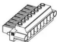
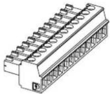
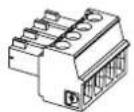
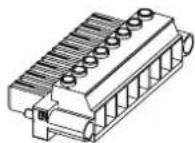
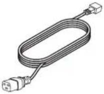
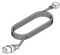
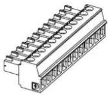
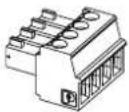
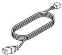
Package Contents
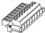
AC power cord 4-pin Euroblock connector 8-pin Euroblock connector 12-pin Euroblock connector

natural_image
Illustration of a coiled electrical cable with two connectors (no text or symbols)×1 ×1 ×1 ×3


natural_image
Technical line drawing of a mechanical connector with multiple slots and a central shaft (no text or symbols)Technical Information
For additional technical information including specifications, block diagrams, and AC current draw statistics, please visit the PowerShareX product page on BoseProfessional.com.
| PSX1204D PSX2404D | PSX4804D | ||
| Amplifier Power 4 × 300 W 4 × 600 W 4 × 1200 W | |||
| Operating Temperature Range 0 °C to 35 °C | |||
| Storage Humidity 10% to 85% humidity | |||
| Dimensions (H × W × D) 44.5 mm | × 483.0 mm × 358.0 mm (1.75 in × 19.02 in × 14.09 in) | ||
| Net Weight | 7.0 kg (15.4 lbs) | ||
ControlSpace Designer
Before configuring your PowerShareX amplifiers, download the latest version of ControlSpace Designer at BoseProfessional.com.
If all the network connections and settings are done correctly, ControlSpace Designer should automatically identify the PowerShareX amplifier on the network.
Connect the PowerShareX to the ControlSpace network, power on the amplifier, and open ControlSpace Designer to discover, update, and configure the amplifier.
For full details on using ControlSpace Designer to configure, control, and monitor the amplifier or systems built with Bose Professional networked system electronics, consult the ControlSpace Designer help system.
Setup Placement
For placement of the amplifier, keep the following in mind:
• Make sure that air can circulate freely from front to back for adequate ventilation. There are vents on the front, back, and sides of the amplifier.
• Do not cover or block amplifier vents.
• Make sure the chassis is protected from heat and kept away from direct heat sources, such as heating vents and radiators.
- Secure both front and rear brackets to the rack.
- Connect the AC Mains connector to a circuit breaker.
• Install the amplifier far from EMF-emitting devices.
- Avoid placing the amplifier close to heat generating sources.
Rack Mounting

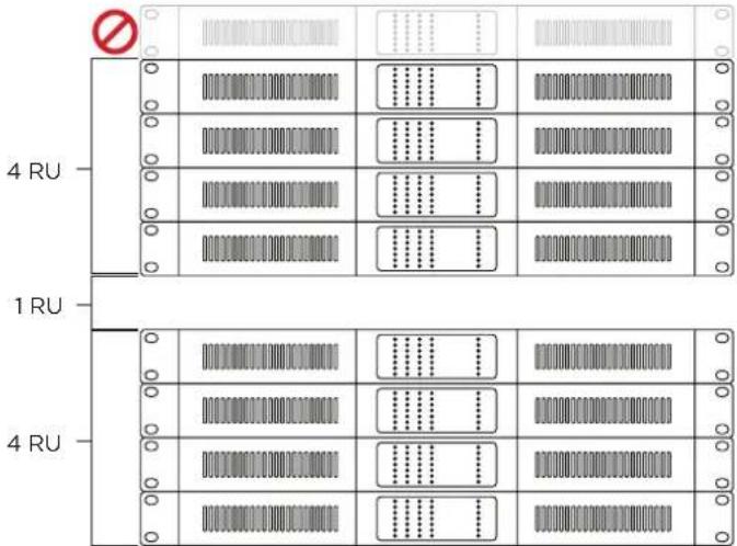
CAUTION: Leave 1 RU of space between every collection of four amplifiers to guarantee adequate air flow.

CAUTION: Due to ventilation requirements, do not place the product in a confined space such as in a wall cavity or in an enclosed cabinet. Do not allow the chassis to exceed the
maximum operating temperature of 35 ^ ( 95 ^ ). Be aware of conditions in an enclosed rack that may increase the temperature above room-ambient conditions. If the amplifier becomes too hot, it will go into a thermal protection mode and mute all outputs.
PowerSpaceX amplifiers are designed to fit standard 48-centimeter (19-inch) rack equipment, occupying one rack-unit (RU) in height (4.4 cm/1.7 in), requiring a mounting depth of 35.8 centimeters (14 inches) from the front rack rail. Use four fasteners with washers (not supplied) to mount the amplifier front panel rack ears to the equipment rack rails.
Cooling
- The ventilation openings must not be impeded by any item, keep a distance of at least 50 mm from the front and rear ventilation openings of the amplifier.
- PowerShareX amplifiers implement a forced-air cooling system to maintain constant operating temperatures. Air enters from the front panel, exiting at the back of the amplifier.
- The cooling system features variable-speed DC fans controlled by the heat-sink mounted sensors. This ensures that fan noise and internal dust accumulation are kept to a minimum.
- In the rare event of overheating, sensing circuits shut down all channels until the amplifier cools down to a safe operating temperature. Normal operation is resumed automatically without the need for user intervention.
PowerShareX PSX1204D/PSX2404D/PSX4804D
Front Panel (cover removed)
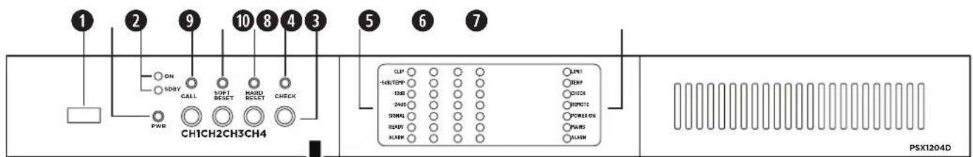
Note: Access the front panel by removing the left faceplate and vent filter. The faceplate is secured by magnets.
① Service port: For service only.
2 Power button: To switch between system On and Standby mode, press and hold for three seconds. If desired, the operating condition can be modified by the GPI/Remote (Remote On/Off).
③ Operating Mode LEDs: The LED will light green to indicate whether the amplifier is On or in Standby mode.
| LED | Light Color & Pattern | Indication |
| ON | Off | Amplifier is powered off |
| ON | Solid green | Amplifier is powered on |
| SDBY | Off | Amplifier is powered on |
| SDBY | Solid orange | Amplifier is in standby mode |
| SDBY | Blinking orange | Amplifier is in auto-standby mode |
| SDBY | Blink "counter" (pattern of blinks) | Error code; contact Bose Professional technical support |
4 Callback button: Reserved for future use.
5 Soft Reset button: Resets network parameters to default settings (DHCP). Press and hold for three seconds.
6 Hard Reset button: Restarts amplifier. Settings and loudspeaker EQs/presets are unaffected. Can be used to cycle power when rear panel is inaccessible. Press and hold for three seconds.
Note: To reset the amplifier to factory settings (DHCP), press and hold both the Soft Reset and Hard Reset buttons for three seconds. This removes loudspeaker EQs/presets and resets any adjusted settings.
⑦ Self Check button: For service only.
8 Channel Attenuation controls: Attenuation controls for the output level of each channel. This affects analog inputs, Dante inputs, and pink-noise generator. Turn the controls clockwise to decrease attenuation and counter-clockwise to increase attenuation. Output level can also be adjusted with ControlSpace Designer.
Note: The attenuation control is in series with the Remote Level connector to limit the output volume regardless of any remote adjustment.
9 Channel Status LEDs: Status LED signal metering for Channels 1, 2, 3, and 4. See the table below for details;
| LED Name Light Color & Pattern2 | Signal Metering | Other Indication | |
| CLIP Orange | User Limiter | Channel limiter | |
| -6dB/TEMP Solid yellow -6 dB | Thermal warning: thermal is protection engaged | ||
| -6dB/TEMP | Steady flashing yellow | -6 dB | Standby |
| -12dB | Green | -12 dB | — |
| -24dB | Green | -24 dB | — |
| SIGNAL | Solid green | -60 dB | Signal presence |
| SIGNAL | Blinking green | -60 dB | Channel is muted |
| READY | Solid green | — | Channel is ready |
| READY | Blinking green | — | Amplifier is in auto-standby |
| ALARM | Solid red | — | Channel fault |
10 System Status LEDs: System status indicators. See the table below for details.
| LED Name Light Color & Pattern ^2 | Indication | |
| LIMIT | Pulse flashing orange | Breaker Save is enabled |
| LIMIT | Solid orange | Breaker Save is limiting power draw |
| TEMP | Solid yellow | Thermal warning; thermal is protection engaged |
| CHECK | Solid orange | System is self-checking |
| CHECK | Blinking orange | Self-check is complete |
| CHECK | Fast-blinking orange | Self-check is unavailable |
| REMOTE | Solid green | Reserved for future use |
| REMOTE | Off | — |
| POWER ON | Solid green | System is ready |
| POWER ON | Off | System is off |
| MAINS | Solid green | AC mains voltage is within operating range |
| MAINS | Off | Under-voltage |
| MAINS | Pulse-flashing green | Over-/under-voltage warning |
| MAINS | Fast-blinking green | Over-voltage |
| MAINS | Blinking green | Blown mains fuses |
| ALARM | Solid red | PSU fault or critical faults |
Notes:
- Does not indicate signal clipping. View channel limiter activity in ControlSpace Designer while on-line for channel limiting indication.
- Timing patterns of System Status and Channel Status LEDs:
| Lighting | Timings | Behavior |
| Pulse flashing | 100 ms on400 ms off | |
| Steady flashing | 100 ms on900 ms off | |
| Fast blinking | 100 ms on100 ms off | |
| Blinking | 500 ms on500 ms off |
Rear Panel
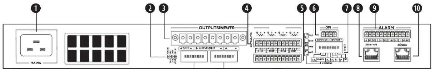
Power input: Power cord connection. Removing the power cord when the amplifier is on is an acceptable power-down method.
② Output Configuration DIP switches: Any mixed configuration of low and high impedance output loads can be made using the four switches for each channel.
70V/100V: Switch the channel output operation between 70 volts and 100 volts.
Lo-Z/Hi-Z: Switch the channel output impedance between low impedance and high impedance.
35Hz/70Hz: Switch the high pass filter frequency between 35 Hz and 70 Hz.
HPF Off/HPF On: Activate or deactivate the channel output high-pass filter. Recommended for 70V/100V outputs if software bandpass high-pass is not engaged.
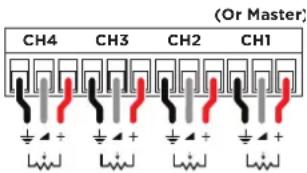
3 Output connector: An eight-terminal connector for loudspeaker connections. Each channel can deliver up to 300 watts (PSX1204D), 600 watts (PSX2404D), or 1200 watts (PSX4804D) of symmetrical power.
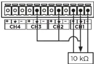
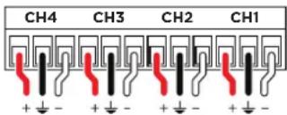
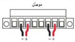
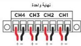
4 Remote Level connector: The level of each channel can be adjusted remotely by a remote level control (linear 10 kΩ potentiometer) connected to the input LEVEL connector for that channel. Connect to Channel 1 and set CHI MSTR DIP switch to On to control all four channels from one controller. Alternatively, to enable remote level adjustment of two or three channels simultaneously, connect the potentiometer's resistive variable pin to multiple channels in parallel (refer to the example diagram where the potentiometer is controlling Channels 1-3). The remote level controls are in series with the Channel Attenuation controls.
Note: ControlCenter CC-1, CC-2, and CC-3 are not compatible with PowerShareX amplifiers.
5 Line Input connector: Line-level input for balanced analog audio signals.
⑤ GPI/Remote connector: Remote on and off control. Both pair of terminals respond to the differential voltage between the contacts: a voltage difference between 5 VDC and 24 VDC triggers the control. Remote off can be used to mute the amplifier. The terminals act differently depending on the actual state of the amplifier:
Voltage applied to contacts
| Current State | Change | Result State | Remote On | Remote Off |
| Amplifier is in Standby | V ≥ 5V applied to REMOTE ON only | Amplifier exits standby;ON LED lights solid green | Vdiff ≥ 5V | Vdiff < 3V |
| Amplifier is On | V ≥ 5V applied to REMOTE OFF only | Amplifier enters standby;SDBY LED lights solid orange -6dB/TEMP LED steady flashes yellow | Vdiff < 3V | Vdiff ≥ 5V |
| Amplifier is in either state | V ≥ 5V applied to REMOTE ON and REMOTE OFF simultaneously | Amplifier exits standby;ON LED lights solid green;If amplifier is already on, no change | Vdiff ≥ 5V | Vdiff ≥ 5V |
| V < 3V applied to REMOTE ON and REMOTE OFF simultaneously | No change | Vdiff < 3V | Vdiff < 3V |
Remote On/Off
Remote Level
Remote Level Connector
Input

CAUTION: Any voltage exceeding 28 VDC may damage the input circuitry.
⑦ System Configuration DIP switches: DIP switches to control overall system output and performance.
| Input Gain Selection | |||||||
| 26 dB | 29 dB | 32 dB | 35 dB | CH1 Master | BRK Save | NRG Save | 2Ω |
CH1 MSTR: When the CH1 MSTR switch is OFF, remote-level potentiometers work independently for each channel. When the CH1 MSTR switch is ON, the remote-level potentiometer of Channel 1 acts as a master level, controlling the volume of all four channels.
GAIN: Adjust the global input gain sensitivity to 35 dB, 32 dB, 29 dB, or 26 dB by following the configuration diagrams on the rear of the amplifier. This feature is designed to match the voltage of the input signal. PowerShareX amplifiers ship with gain sensitivity set to 32 dB by default.
Note: For most situations, leave this set to 32 dB gain. The 35 dB gain setting is similar to PowerMatch 8500N (36 dB). Analog gain sensitivity cannot be further adjusted through ControlSpace Designer. Digital input sensitivity can also be adjusted through ControlSpace Designer.
BRK SAVE (Breaker Save): Switch to ON when (1) the power grid is unable to provide enough current to continuously drive the loads, or (2) when at least one of the amplifiers connected to the same outlet can reach the critical power absorption of the line. When activated, the Breaker Save halves the maximum continuous current absorption from the mains, which reduces the available output power. This will be indicated by the LIMIT System Status LED on the front panel. This will affect overall performance of the amplifier.
NRG SAVE (Energy Save): The power supply unit allows a reduction in power consumption when the input signal falls under a defined threshold. When ON, Energy Save is active on each channel independently. If the signal is absent for more than 30 minutes on all channels, auto standby is applied and the main PSU is turned off to further conserve energy (Time out time is selectable via ControlSpace Designer). Normal operation resumes immediately upon detecting a signal.
Note: USR A, USR B, and USR C (PSX4804D only) are unavailable.
2Ω: PowerShareX amplifiers are optimized for working with 4Ω output loads, but the 2Ω switch allows loads down to 2Ω. Switch to ON to activate an operating condition that optimizes the performance with very low loads by limiting the maximum output voltage to 85 V _max per channel. This affects all output channels set to match low impedance (i.e., in Lo-Z configuration). For optimal 2Ω performance, switch the Lo-Z/Hi-Z Output Configuration DIP to Lo-Z for all channels.
Note: PSX1204D and PSX2404D only. PSX4804D can also handle 2Ω loads without the use of a DIP switch.
8 Ethernet port: RJ45 connector. Remotely control the amplifier via an Ethernet connection through a personal computer and ControlSpace Designer software.
9 GPO/Alarm connector: There are general-purpose output connections for each channel: one Normally Open (NO), one Normally Closed (NC), and one channel number connection that acts as a ground (1-4). At least two connections are required to report and detect a change (e.g., 3 and NC). When the amplifier is in normal operating condition, the NO contacts are closed and the NC contacts are open. These contacts are toggled to indicate a potentially dangerous fault, unsafe operating condition, or any fault preventing normal output channel operation, including the following: Alarm
| Across all channels: | No AC mains (i.e. system shutdown).Thermal stress: the system temperature is too high and the thermal protection is engaged.Amplifier is in standby mode. |
| Affected channels only: | Short circuit in output wiring: either the loudspeaker or the line is in short. Alarm is sent out the specific output channel with the short circuit event. |
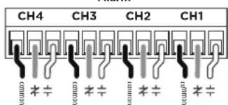
NC/NO connections of multiple channels can be combined if needed. See ControlSpace Designer for additional alarm and monitoring options.
10 Dante port: RJ45 connector. PowerShareX accepts four input streams from the Dante* connection through the Dante port. Use a computer running Dante Controller to implement a Dante network. Dante Controller is a software application that manages devices on the network.
Setting Up a PowerShareX Amplifier
- Make all output and input audio connections.
- Connect your computer to your amplifier's Ethernet port using a Cat 5e cable, or use a network switch.
- Connect Dante network audio to the amplifier's Dante * port.
- Ensure all Channel Attenuation front panel controls are fully clockwise or at their desired levels. This affects analog, Dante, and pink noise levels.
- Configure your loudspeakers by adjusting the Output Configuration DIP switches and the System Configuration DIP switches to the desired parameters for your installation.
A. Use the PowerShare Design Tool (found at BoseProfessional.com) to help plan your system design.
B. If outputs are set to drive 70V/100V Hi-Z loudspeakers, ensure Channel Attenuation control is fully clockwise to 0 dB attenuation. Set each loudspeaker tap to the appropriate setting. Based on the total loudspeaker tap settings, the amplifier will adapt and deliver the required power to each output. The total amplifier wattage can be distributed in any way across all amplifier outputs.
C. Since each output is configurable to drive either Hi-Z or Low-Z loudspeakers, the amplifier can support mixed-impedance installations. In this setup, first configure the Hi-Z channels before configuring the Low-Z channels.
- Configure any remote controls using the Remote Level connector.
A. If using a potentiometer for remote control, rotate each Channel Attenuation control fully clockwise to 0 dB attenuation. This enables each controller to attenuate over the full range. To have the controller operate across a limited range, increase the attenuation as needed by rotating the Channel Attenuation control counter-clockwise.
Note: There is no ground switch or terminal on PowerShareX amplifiers. The unit's signal grounding system is automatic. In order to limit hum and/or interference entering the signal path, use balanced input connections.
-
Connect power cable to the amplifier and connect it to an appropriate power source.
-
Start ControlSpace Designer on your computer and configure each signal processing block as required for the application. See the ControlSpace Designer help system for details. By default, sources are configured for analog inputs and must be changed to digital if Dante network audio is desired. ControlSpace Designer can be used to select an input type.
- If the amplifier is in Standby, press and hold the Power button for three seconds to turn on the amplifier.
- When setting up the amplifier, monitor the Limit indicators for each channel in ControlSpace Designer (while amplifier is on-line) and the System Status LEDs on the front amplifier for operating faults. Make adjustments if necessary.
Technical Considerations:
When a loudspeaker EQ is selected in ControlSpace Designer, the appropriate crossover and V_Peak and V_RMS limiters for that loudspeaker are automatically loaded.
Adjusting the Channel Attenuation control of a single channel does not affect the level of other channels. The only exception is if the amplifier is attempting to deliver more than the total amplifier wattage. If the total amplifier power is exceeded, the amplifier will limit all outputs simultaneously and equally until the demand is reduced. If the demand remains too high, the amplifier will gradually limit power.
There are multiple ways to adjust output power in a PowerShareX amplifier application:
- Adjust input signal level relative to the sensitivity setting of the channel.
- Adjust the Matrix level in ControlSpace Designer.
- Adjust the output levels in ControlSpace Designer.
- Adjust the Channel Attenuation controls of the amplifier.
- Adjust the limiter settings for each output using ControlSpace Designer.

CAUTION: Increasing the voltage to a level higher than the preset may damage the loudspeaker.
- Adjust the transformer tap settings of any connected Hi-Z loudspeakers.
- Mute analog outputs with the GPI/Remote connector, switching the amplifier to standby.
• If combining with PowerMatch PM8500N, add 1.5 ms latency to PowerMatch to match the increased latency of PowerShareX.
• To set amplifier for Auto Standby, use the NRG Save DIP switch and select Auto Standby in ControlSpace Designer.
Networking
PowerShareX amplifiers have two RJ45 Ethernet ports: the Ethernet port is for network communication/control; the Dante port is for Dante streaming audio. Two separate Cat 5e cables are needed to use both ports. PowerShareX amplifiers do not support bridging with a single cable.
IP Addressing
Factory default network settings are DHCP.
If using a DHCP server, it is recommended to turn on and connect the DHCP server to the network before powering on the amplifier to ensure a valid IP address is acquired.
A static IP is recommended and can be configured though ControlSpace Designer. The amplifier and ControlSpace Designer must belong to the same subnet to be discovered and configured though ControlSpace Designer.
If a DHCP server is not present while the amplifier boots, the amplifier will be configured with a link local address in the 169.254.0.0/16 subnet.
Care & Maintenance
When cleaning the amplifier, keep the following in mind:
- Use a dry cloth to clean the chassis and the front panel.
- Vent filter cleaning should be scheduled in accordance with the dust levels in the amplifier's operating environment.
- In order to clean the vent filters remove the front panel faceplates by pulling them away from the amplifier to disengage the magnets. Use compressed air to remove dust from the filters, or wash them with clean water. Let the filters dry thoroughly before reinstalling them.
www.Bose.com/compliance

Importador de China: Base Electronics (Shanghai) Company Limited, Level 6, Tower D, No. 2337 Gudai Rd. Minhang District, Shanghai 20100, China
Importador del Reino Unido: Bose Limited Bose House, Guayside Chatham Maritime, Chatham, Kent, ME4 40Z, Reino Unido
natural_image
Line drawing of a U-shaped electrical cable with two connectors (no text or symbols)×11 ×11 ×11 ×3
natural_image
Technical line drawing of a mechanical connector or terminal block (no text or symbols)Información técnica
Importeur aus China: Bose Electronics (Shanghai) Company Limited, Level 6, Tower D, No. 2337 Gudai Rd. Minhang District, Shanghai 201100
Bose Corporation, Framingham, MA 01701, USA. +1 877 230 5639
Importatore per la Cina: Bose Electronics (Shanghai) Company Limited, Level 6, Tower D, No. 2337 Gudai Rd. Minang District, Shanghai 201100
Section 3, Minsheng East Road, Taipei City 104, Taiwan
natural_image
Illustration of a coiled electrical plug with two terminal connectors (no text or symbols)×1pz. ×1pz. ×1pz. ×3pz

natural_image
Technical line drawing of a multi-pin electrical connector (no text or symbols)Importeur In China: Base Electronics (Shanghai) Company Limited, Level 6, Tower D, No. 2337 Gudai Rd, Minhang District, Shanghai 201100
Importeur in het VK: Bose BV, Gorslaan 60. 1441 RG Purmerend
Importeur in de EU: Bose Products B.V., Gorslaan 60, 1441 RG Purmerend, Nederland
Importeur In Mexico: Bose de México, S. de R.L. de C.V., Paseo de las Palmas 405-204, Lomas de Chapultepec, 11000 Mexico, D.F. Gegevens importeur en service-informatie: +52 55 52 02 35 45
Importeur in Taiwan: Bose Taiwan Branch, 9F-41, No. 10, Sedion 3, Minsheng East Road, Taipei City 104, Taiwan. Telefoonnummer: +886 2 25 14 76 76
Bose Corporation, Framingham, MA 01701, VS 1877 230 5639
| Netsnoer 4-pins Euroblock-connector 8-pins Euroblock-connector 12-pins Euroblock-connector | |||
 ×1 ×1 ×1 ×3 ×1 ×1 ×1 ×3 | 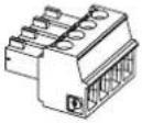 | 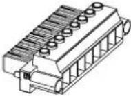 |  |
Importer i Kina: Bose Electronics (Shanghai) Company Limited, Level 6, Tower D, No. 2337 Gudai Rd. Minhang District, Shanghai 201100
Importer I Storbritannia: Bose Limited Bose House, Quayside Chatham Maritime, Chatham, Kent, ME4 4QZ, Storbritannia
Importer I EU: Bose Products B.V., Gorslaan 60, 1441 RG Purmerend, Nederland
Importar i Mexico: Bose de México, S. de R.L. de C.V., Paseo de las Palmas 405-204, Lomas de Chapultepec, 11000 México, D.F. For importar - og serviceinformasjon: +5255 (5202) 3345
Importer I Taiwan: Bose Taiwan Branch, 9F-A1, No. 10, Section 3, Minsheng East Road, Taipei City 104, Taiwan. Telefonnummer: +886-2-2514 7676
Bose er et varemerke for Bose Corporation.
Strømkabel 4-pinners
Euroblock-kontakt 8-pinners Euroblock-kontakt 12-pinners Euroblock-kontakt
natural_image
Illustration of a coiled electrical cable with two connectors (no text or symbols)×1 ×1 ×1 ×3


natural_image
Technical line drawing of a mechanical connector with multiple slots and a central shaft (no text or symbols)Teknisk informasjon
⑦ Knapp for egenkontroll: Kun for service.
Importer w Chinach: Bose Electronics (Shanghai) Company Limited, Level 6, Tower D, No. 2337 Gudai Rd, Minhang District, Shanghai 201100
Importer na Tajwanie: Bose Taiwan Branch, 9F-A1, No. 10, Section 3, Minsheng East Road, Taipei City 104, Tajwan.
Numer tel: +886-2-2514 7676
英国进口商:Bose Limited Bose House, Quayside Chatham Maritime, Chatham, Kent, ME4 4QZ, United Kingdom
欧洲进口商:Bose Products B.V., Gorslaan 60, 1441 RG Purmerend, The Netherlands
墨西哥进口商:Bose de México, S. de R.L. de C.V., Paseo de las Palmas 405-204, Lomas de Chapultepec, 11000 México, D.F. 如需获取进口商和服务信息,请拨打电话:+5255 (5202) 3545
www.Bose.com/compliance
英國進口商:Bose Limited Bose House, Quayside Chatham Maritime, Chatham, Kent, ME4 4QZ, United Kingdom
歐盟進口商 Bose Products B.V., Gorslaan 60, 1441 RG Purmerend, The Netherlands
墨西哥進口商. Bose de México, S. de R.L. de C.V., Paseo de las Palmas 405-204, Lomas de Chapultepec, 11000 México, D.F. 進口商與服務資訊: +5255 (5202) 3545
This device complies with part 15 of the FCC Rules. Operation is subject to the following two conditions: (1) This device may not cause harmful interference, and (2) this device must accept any interference received, including interference that may cause undesired operation.
NOTE: This equipment has been tested and found to comply with the limits for a Class A digital device, pursuant to part 15 of the FCC Rules. These limits are designed to provide reasonable protection against harmful interference when the equipment is operated in a commercial environment. This equipment generates, uses, and can radiate radio frequency energy and, if not installed and used in accordance with the instruction manual, may cause harmful interference to radio communications. Operation of this equipment in a residential area is likely to cause harmful interference in which case the user will be required to correct the interference at their own expense.
Changes or modifications not expressly approved by Bose Professional could void the user's authority to operate this equipment. WARNING: This is a class A product. In a domestic environment this product may cause radio interference in which case the user may be required to take adequate measures.
This product meets all EN55103-2 immunity requirements for E2 electromagnetic environment.
中国における輸入元: Bose Electronics (Shanghai) Company Limited, Level 6, Tower D, No. 2337 Gudai Rd, Minhang District, Shanghai 201100
英国における輸入元: Bose Limited Bose House, Quayside Chatham Maritime, Chatham, Kent, ME4 4QZ. United Kingdom EUIにおける輸入元: Bose Products B.V., Gorslaan 60, 1441 RG Purmerend, The Netherlands
m = 311
广力云智慧零售收银系统
广力云
m = 311
m = 311
m = 311
-
m = 311
-
m = 311
-
-
m = 311
-
m = 311
m = 311
m = 311
-
m = 311
-
-
-
-
-
m = 311
-
-
m = 311
m = 311
-
-
-
m = 311
m = 311
محتويات العبوة
 |  |  |  × 1 × 1 × 1 × 3 × 1 × 1 × 1 × 3 |
المعلومات الفنية
مستوى التحكم عن بعد

- PowerShareX
- Please read and keep all safety and use instructions.
- WARNINGS/CAUTIONS
- Product Ratings
- Regulatory Information
- CAN ICES-3 (A)/NMB-3(A)
- Warranty Information
- Package Contents
- Technical Information
- ControlSpace Designer
- Setup Placement
- Rack Mounting
- Cooling
- PowerShareX PSX1204D/PSX2404D/PSX4804D
- Notes:
- Setting Up a PowerShareX Amplifier
- Technical Considerations:
- Networking
- IP Addressing
- Care & Maintenance
- Información técnica
- Teknisk informasjon
Brand : BOSE
Model : PowerShareX PSX2404D
Category : Receiver