EXM-ProSub - Subwoofer YORKVILLE - Free user manual and instructions
Find the device manual for free EXM-ProSub YORKVILLE in PDF.

User questions about EXM-ProSub YORKVILLE
0 question about this device. Answer the ones you know or ask your own.
Ask a new question about this device
Download the instructions for your Subwoofer in PDF format for free! Find your manual EXM-ProSub - YORKVILLE and take your electronic device back in hand. On this page are published all the documents necessary for the use of your device. EXM-ProSub by YORKVILLE.
USER MANUAL EXM-ProSub YORKVILLE
text_image
World map composed of black dots representing data points, with some dots marked as '0' or '1'.
WEB: www.yorkville.com
WORLD HEADQUARTERS
CANADA
Yorkville Sound Limited
550 Granite Court
Pickering, Ontario
L1W 3Y8 CANADA
Voice: 905-837-8481
Fax: 905-839-5776
U.S.A.
Yorkville Sound Inc.
4625 Witmer Industrial Estate
Niagara Falls, New York
14305, USA
Voice: 716-297-2920
Fax: 716-297-3689
Quality and Innovation Since 1963
Printed in Canada

SERVICE MANUAL
EXM ProSUB
SMT Disclaimer
Due to the complex nature of the use of SMT installed components in Yorkville equipment, we highly caution all service technicians in attempting to repair or replace SMT factory installed components.
Many of these components may be glued prior to initial soldering
Replacing SMT components requires expensive
specialized de-soldering equipment and training.
Yorkville Sound will repair and replace defective SMT components to ensure proper quality assurance and installation is maintained.
IMPORTANT SAFETY INSTRUCTIONS

This lightning flash with arrowhead symbol, within an
equilateral triangle, is intended to alert the user to the presence of uninsulated "dangerous voltage" within the product's enclosure that may be of sufficient magnitude to constitute a risk of electric shock to persons.
The DO NOT STACK symbol is inlanded to alert the user that the product shall not be vertically slacked because of the nature of the product.
The excitation point within an equilateral triangle is intended to alert the user to the presence of important operating and maintenance (servicing) instructions in the literature accompanying the appliance.
Instructions pertaining to a risk of fire, electric shock, or injury to a person
CAUTION: TO REDUCE THE RISK OF ELECTRIC SHOCK, DO NOT REMOVE COVER (OR BACK). NO USER SERVICEABLE PARTS INSIDE. REFER SERVICING TO QUALIFIED SERVICE PERSONNEL. THIS DEVICE IS FOR INDOOR USE ONLY! INSTALLED BATTERY PACKS SHALL NOT BE EXPOSED TO EXCESSIVE HEAT SUCH AS SUNSHINE, FIRE OR THE LIKE.
Read Instructions: The Owner's Manual should be read and understood before operation of your unit. Please, save these instructions for future reference and heed all warnings.
Cleaning: Clean only with dry cloth.
Packaging: Keep the box and packaging materials, in case the unit needs to be returned for service.
Warning: To reduce the risk or fire or electric shock, do not expose this apparatus to rain or moisture. Do not use this apparatus near water!
Warning: When using electric products, basic precautions should always be followed, including the following:
Power Sources
Your unit should be connected to a power source only of the voltage specified in the owners manual or as marked on the unit. This unit has a polarized plug. Do not use with an extension cord or receptacle unless the plug can be fully inserted. Precautions should be taken so that the grounding scheme on the unit is not defeated. An apparatus with CLASS I construction shall be connected to a Mains socket outlet with a protective earthing connection. Where the MAINS plug or an appliance coupler is used as the disconnect device, the disconnect device shall remain readily operable.
Hazards
Do not place this product on an unstable cart, stand, tripod, bracket or table. The product may fail, causing serious personal injury and serious damage to the product. Use only with cart, stand, tripod, bracket, or table recommended by the manufacturer or sold with the product. Follow the manufacturer's instructions when installing the product and use mounting accessories recommended by the manufacturer. Only use attachments/abs Accessories specified by the manufacturer.
Equipment that is suspended overhead must use a secondary safeguard to prevent personal injury in the event the primary mounting mechanism fails. Safety eyebolts attached to the equipment and galvanized steel wire can be used together to implement a fallsafe mounting thus ensuring the safety of the equipment and anyone positioned below the equipment.
Improper installation can result in bodily injury or death. If you are not qualified to attempt the installation get help from a professional structural rigger. Notes: Prolonged use of headphones at a high volume may cause health damage to your ears.
The apparatus should not be exposed to dripping or splashing water; no objects filled with liquids should be placed on the apparatus.
Terminals marked with the "lightning bolt" are hazardous live; the external wiring connected to these terminals require installation by an instructed person or the use of ready made leads or cords.
Ensure that proper ventilation is provided around the appliance. Do not install near any heat sources such as radiators, heat registers, sloves, or other apparatus (including amplifiers) that produce heat.
No naked flame sources, such as lighted candles, should be placed on the apparatus.
Power Cord
Do not defeat the safety purpose of the polarized or grounding-type plug. A polarized plug has two blades with one wider than the other. A grounding type plug has two blades and a third grounding prong. The wide blades or the third prong are provided for your safety. If the provided plug does not fill into your outlet, consult an electrician for replacement of the obsolete outlet. The AC supply cord should be routed so that it is unlikely that it will be damaged. Protect the power cord from being walked on or pinched particularly at plugs. If the AC supply cord is damaged DO NOT OPERATE THE UNIT. To completely disconnect the apparatus from the AC Mains, disconnect the power supply cord plug from the AC receptacle. The mains plug of the power supply cord shall remain readily operable.
Unplug this apparatus during lightning storms or when unused for long periods of time.
Service
The unit should be serviced only by qualified service personnel. Servicing is required when the apparatus has been damaged in any way, such as power-supply cord or plug is damaged, liquid has been spilled or objects have fallen into the apparatus, the apparatus has been exposed to rain or moisture, does not operate normally, requires battery pack replacement or has been dropped. Disconnect power before servicing!
IMPORTANT SAFETY INSTRUCTIONS

The Lightning Flash with arrowhead symbol within an equilateral triangle, is intended to alert the user to the presence of uninsulated "dangerous voltage" within the product enclosure that may be of sufficient magnitude to constitute a risk of shock to persons

The exclamation point within an equilateral triangle is intended to alert the user to the presence of important operating and maintenance (servicing) instructions in the literature accompanying the product
-
Read these instructions.
-
Keep these instructions.
-
Head all warnings.
-
Follow all instructions.
-
Do not use this apparatus near water.
-
Clean only with dry cloth.
-
Do not block any ventilation openings. Install in accordance with the manufacturer's instructions.
-
Do not install near any heat sources such as radiators, heat registers, stoves, or other apparatus (including amplifiers) that produce heat.
-
Do not defeat the safety purpose of the polarized or grounding-type plug. Apolarized plug has two blades with one wider than the other. A grounding type plug has two blades and a third grounding prong. The wide blade or the third prongs are provided for your safety. If the provided plug does not fit into your outlet, consult an electrician for replacement of the obsolete outlet.
-
Protect the power cord from being walked on or pinched particularly at plugs, convenience receptacles, and the point where they exit from the apparatus.
-
Only use attachments/accessories specified by the manufacturer.
-
Use only with the cart, stand, tripod, bracket, or table specified by the manufacturer, or sold with the apparatus. When a cart is used, use caution when moving the cart/apparatus combination to avoid injury from lip-over.
-
Unplug this apparatus during lightning storms or when unused for long periods of time.
-
Refer all servicing to qualified service personnel. Servicing is required when the apparatus has been damaged in any way, such as power-supply cord or plug is damaged, liquid has been spilled or objects have fallen into the apparatus, the apparatus has been exposed to rain or moisture, does not operate normally, or has been dropped.
WARNING:
• To reduce the risk of fire or electric shock, do not expose this apparatus to rain or moisture and objects filled with liquids, such as vases, should not be placed on this apparatus.
• To completely disconnect this apparatus from the ac mains, disconnect the power supply cord plug from the ac receptacle.
- The mains plug of the power supply cord or appliance coupler shall remain readily accessible.

text_image
EXM ProSUB POWER www.yorkville.com FUSE TRAIL 1200kV 1200kV 1250mA 1250mA 1250mA 1250mA 1250mA 1250mA 1250mA 1250mA 1250mA 1250mA 1250mA 1250mA 1250mA 1250mA 1250mA 1250mA 1250mA 12.50kV 12.50mA 12.50mA 12.50mA 12.50mA 12.50mA 12.50mA 12.50mA 12.50mA 12.50mA 12.50mA 12.50mA 12.50mA 12.50mA 12.50mA 12.50mASpecifications
Active or Passive Active
Program Power (watts) 500 watts, program (800 watts, peak)
Measured Max SPL (C-Weighted, Max Hold) 122dB Continuous, 128 dB Peak
Frequency Response (Hz +/- 3dB) 47Hz-100Hz
Crossover Frequency (Hz) 100 Hz Lowpass
Cabinet Configuration Bass Reflex
Driver Configuration 2x 10-inch LF woofer
LF Driver(s) 2x10-inch Neo with 2-inch Voice Coil
LF Impedance (ohms) 4 ohm Load (2x 8 ohm in Parallel)
LF Protection Excursion, Voice Coil Thermal (RMS)
LF Amplifier Type Class D
Cooling Scheme Convection
Power Cable Yes
Power Switch Yes
Power Consumption 150VA
Inputs 2x (L&R) XLR / ¼-inch Combi-jack, Bluetooth™, 3.5mm Stereo,
Outputs 2x XLR (L&R)High Pass Out, XLR Full Range Mix Out
Level Controls Sub Level
Limiter Excursion, Thermal (RMS), Clipping
LED Indicators Power, Bluetooth™, Battery Level, Charging Status, Clip
Enclosure Materials 15 mm Birch Plywood
Stacking Feature Interlocking Rubber Feet (top/bottom)
Covering / Finish ABS Laminated
Dimensions (DWH, inches) 20/15.5/27
Dimensions (DWH, cm) 51/39/60
Weight (lbs/kg) 67/30.5
Specifications subject to change without notice
Spécifications
Active ou Passive Active
Puissance Nominale (watts) 500 watts, programme (800 watts, crête)
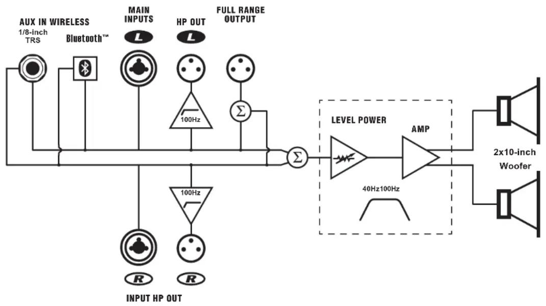
Block Diagram for EXM ProSUB
DESIGNED & MANUFACTURED BY YORKVILLE SOUND
flowchart
graph LR
    A["INPUT HP OUT"] --> B["R"]
    B --> C["100Hz"]
    C --> D["AMP"]
    D --> E["2x10-inch Woofer"]
    E --> F["LEVEL POWER"]
    F --> G["40Hz100Hz"]
    G --> H["FULL RANGE OUTPUT"]
    H --> I["AUX IN WIRELESS 1/8-inch TRS"]
    I --> J["Bluetooth™"]
    J --> K["MAIN INPUTS L"]
    K --> L["HP OUT L"]
    L --> M["Σ"]
    M --> N["100Hz"]
    N --> O["Σ"]
    O --> P["INPUT HP OUT"]
    style A fill:#f9f,stroke:#333
    style F fill:#ccf,stroke:#333
    style E fill:#cfc,stroke:#333
M2105-01 Parts Reference List 2023-05-23
| REF | YS # | Description | REF | YS # | Description | REF | YS # | Description | REF | YS # | Description | REF | YS # | Description | REF | YS # | Description |
| 41 | A25 | AMPROSUB INPUT | 01 | COSF 4'48 | 75V 0A15 100S SMT | 035 | W1X | 10K0 % | 890S SMT RLS | 0122 | W100 12K1 % | 890S SMT RLS | |||||
| 41 | 100U | 25V 20%CAP 8.5x 5MT ELE | 02 | COSF 4'48 | 75V 0A15 100S SMT | 036 | W12 | 200K % | 890S SMT RES | 0124 | W120 3K82 % | 890S SMT RES | |||||
| 47 | 0212 100K | 00V 5%CAP TAR RAD 2FLM | 01 | COSF 4'48 | 75V 0A15 100S SMT | 037 | W12 | 081R % | 080S SMT RES | 0124 | W100 2K0 % | 890S SMT RES | |||||
| 47 | 0212 100K | 00V 5%CAP TAR RAD 2FLM | 01 | COSF 4'48 | 75V 0A15 100S SMT | 038 | W10 | 200K % | 890S SMT RES | 0125 | W120 47K5 % | 890S SMT RES | |||||
| 43 | 0220 150K | 85V 10%CAP TAR RAD 2FLM | 05 | COSF 4'48 | 75V 0A15 100S SMT | 039 | W10 | 3K00 % | 890S SMT RES | 0125 | W100 2K0 % | 890S SMT RES | |||||
| 43 | 25U | 00V 5%CAP TAR RAD 2FLM | 08 | COSF 4'48 | 75V 0A15 100S SMT | 040 | W12 | 0A15 500S SMT | 890S SMT | 0127 | W120 3K00 % | 890S SMT RES | |||||
| 43 | 0212 100K | 00V 5%CAP TAR RAD 2FLM | 010 | COSF 4'48 | 75V 0A15 100S SMT | 041 | W12 | 200K % | 890S SMT RES | 0128 | W120 3K82 % | 890S SMT RES | |||||
| 47 | 10U | 16V 20%CAP 50X 4 SMT NP | 011 | COSF 4'48 | 75V 0A15 100S SMT | 042 | W10 | 4K99 % | 890S SMT RES | 0129 | W100 2K48 % | 890S SMT RES | |||||
| 49 | 0212 100K | 00V 5%CAP TAR RAD 2FLM | 012 | COSF 4'48 | 75V 0A15 100S SMT | 013 | W10 | 10K0 % | 890S SMT RES | 0130 | W100 1K0 % | 890S SMT RES | |||||
| 49 | 25U | 16V 20%CAP 50X 5 SMT ELEC | 013 | COSF 4'48 | 75V 0A15 100S SMT | 014 | W10 | 2K09 % | 890S SMT RES | 0131 | W120 33R 5% | 890S SMT RES | |||||
| 410 | 25U | 16V 20%CAP 50X 5 SMT ELEC | 014 | COSF 4'48 | 75V 0A15 100S SMT | 015 | W10 | 10K0 % | 890S SMT RES | 0134 | W120 3K09 % | 890S SMT RES | |||||
| 411 | 22U | 16V 20%CAP 50X 5 SMT ELEC | 014 | COSF 4'48 | 75V 0A15 100S SMT | 016 | W10 | 10K0 % | 890S SMT RES | 0145 | W120 3K82 % | 890S SMT RES | |||||
| 412 | 22U | 16V 20%CAP 50X 5 SMT ELEC | 014 | COSF 4'48 | 75V 0A15 100S SMT | 017 | W20 | 100R % | 1200 SMT RES | 0146 | W120 100K6 % | 890S SMT RES | |||||
| 413 | 22U | 16V 20%CAP 50X 5 SMT ELEC | 015 | COSF 4'48 | 75V 0A15 100S SMT | 018 | W13 | 681R % | 080S SMT RES | 0147 | W100 4X98 % | 890S SMT RES | |||||
| 414 | 0226 150K | 00V 5%CAP TAR RAD 2FLM | 020 | COSF 4'48 | 75V 0A15 100S SMT | 019 | W12 | 1100S SMT | 890S SMT | 0150 | W100 13K0 % | 890S SMT RES | |||||
| 415 | 160P | 50V 5%CAP 680S SMT NPO | 023 | RLZ7 58 | 75V 6W5 6% SMT ZEN | 025 | W13 | 681R % | 080S SMT RES | 025 | W100 18K2 % | 890S SMT RES | |||||
| 416 | 100P | 50V 10%CAP 880S SMT SMT | 024 | 9509 14/6 XLR | PCU MT VLRTI COMBO NUTRJK | 025 | W10 | 10K0 % | 890S SMT HLS | 026 | W120 100K6 % | 890S SMT RES | |||||
| 417 | 0212 100K | 00V 5%CAP TAR RAD 2FLM | 02 | 4140 XLR WALL | PCB MT VLRTI 24MM A-SERILES | 026 | W10 | 10K0 % | 890S SMT HLS | 0235 | W100 1K0 % | 890S SMT RES | |||||
| 418 | 0229 150K | 63V 10%CAP TAR RAD 2FLM | 03 | 4140 XLR WALE | PCB MT VERT 24MM A-SERILES | 031 | W10 | 20K0 % | 890S SMT RES | 0246 | W120 100K6 % | 890S SMT RES | |||||
| 419 | 22U | 16V 20%CAP 50X 5 SMT ELEC | 03 | 4216 3.8MM JOH | PCB MT V ST SPIN SLB 4196 | 034 | W10 | 4K99 % | 890S SMT RES | 0246 | W100 20K5 % | 890S SMT RES | |||||
| 420 | 0229 150K | 63V 10%CAP TAR RAD 2FLM | 05 | 6509 14/6 XLR | PCB MT VERT COMBO NEUTRK | 035 | W10 | 10K0 % | 890S SMT RES | 0250 | W120 3K82 % | 890S SMT RES | |||||
| 421 | __IN | 60V 5%CAP 906S SMT NPO | 06 | 6140 XLR WALL | PCB MT VERT 24MM A-SERILES | 036 | W10 | 15K0 % | 890S SMT RES | 0251 | W120 3K82 % | 890S SMT RES | |||||
| 422 | __IN | 60V 5%CAP 906S SMT NPO | 07 | FIELD LLD | 2V 20MA 1208 SMT | 037 | W10 | 2K1 % | 890S SMT RES | 0255 | W120 582K % | 890S SMT RES | |||||
| 423 | 22U | 25V 20%CAP 50X 5 SMT ELEC | 08 | GRN LED | 2V 20MA 1208 SMT | 038 | W10 | 6M % | 890S SMT RES | 0259 | W120 582K % | 890S SMT RES | |||||
| 424 | 160P | 50V 5%CAP 680S SMT NPO | 08 | RDGN LED | 2V 20MA 0606 SMT | 039 | W10 | 6M % | 890S SMT RES | 0306 | W100 1V0 % | 890S SMT RES | |||||
| 425 | 25U | 16V 20%CAP 50X 5 SMT ELEC | 09 | GRN LED | 2V 20MA 1208 SMT | 040 | W10 | 10K0 % | 890S SMT RES | 0324 | W100 1V0 % | 890S SMT RES | |||||
| 426 | 25U | 16V 20%CAP 50X 5 SMT ELEC | 10 | BLU LE | 2V 20MA 1208 SMT | 041 | W10 | 100R % | 890S SMT RES | 0328 | W100 1V0 % | 890S SMT RES | |||||
| 427 | 0212 100K | 00V 5%CAP TAR RAD 2FLM | 11 | GRN LED | 2V 20MA 1208 SMT | 042 | W10 | 15K0 % | 890S SMT RES | 0329 | W100 1V0 % | 890S SMT RES | |||||
| 428 | 0212 100K | 00V 5%CAP TAR RAD 2FLM | 12 | GRN LED | 2V 20MA 1208 SMT | 043 | W10 | 100R % | 890S SMT RES | 0330 | W100 20K5 % | 890S SMT RES | |||||
| 430 | 160P | 50V 5%CAP 680S SMT NPO | 13 | GRN LED | 2V 20MA 1208 SMT | 044 | W10 | 18K2 % | 890S SMT RES | 0339 | S3439 DPDTI MINI PC VERT MOMENTARY | ||||||
| 431 | 42U | 25V 20%CAP 4X5.5 SMT ELEC | 14 | 4X34 6K 18R IN NUM DIFFNT | 753 | W11 | 20K5 % | 890S SMT RES | 0343 | S353 DPDTI MINI PC VERT EXP AL* | |||||||
| 432 | 100K | 60V 5%CAP 880S SMT NPO | 15 | M393BANK * | 1 OP 200 SCOT-50ON SMT FEXPROSSUR | 036 | W12 | 27K5 % | 890S SMT RES | 0353 | S379 T LCL POLY MIMO LABRE, P Y 3X* | ||||||
| 433 | 100K | 50V 5%CAP 680S SMT XTR | 16 | M3873K9 | 1 PNP SOT-23 SMT TSR | 037 | W10 | 6M % | 890S SMT RES | 038 | TLO3 DUAL OPAMP LOPWR SMT SOICS | ||||||
| 434 | 42U | 25V 20%CAP 4X5.5 SMT ELEC | 17 | M3873K9 | LTI PNP SOT-23 SMT TSR | 038 | W10 | 28K5 % | 890S SMT RES | 039 | TLO3 DUAL OPAMP LOPWR SMT SOICS | ||||||
| 435 | 100P | 50V 10%CAP 980S SMT NPO | 18 | MMB373K9 | NPN DAYL SOT-23 SMT | 039 | W10 | 1M % | 890S SMT RES | 040 | TLO3 DUAL OPAMP LOPWR SMT SOICS | ||||||
| 436 | 42U | 25V 20%CAP 4X5.5 SMT ELEC | 19 | MMB373K9 | NPN DAYL SOT-23 SMT | 040 | W10 | 1M % | 890S SMT RES | 041 | TLO3 DUAL OPAMP LOPWR SMT SOICS | ||||||
| 437 | 100P | 50V 5%CAP 680S SMT XTR | 20 | MMB373K9 | NPN DAYL SOT-23 SMT | 041 | W10 | 1M % | 890S SMT RES | 042 | TLO3 DUAL OPAMP LOPWR SMT SOICS | ||||||
| 438 | 50V 5%CAP 680S SMT XTR | 20 | MMB373K9 | NPN DAYL SOT-23 SMT | 042 | W10 | 1M % | 890S SMT RES | 043 | TLO3 DUAL OPAMP LOPWR SMT SOICS | |||||||
| 439 | 100P | 50V 5%CAP 680S SMT XTR | 21 | MMB373K9 | NPN DAYL SOT-23 SMT | 043 | W10 | 1M % | 890S SMT RES | 044 | TLO3 DUAL OPAMP LOPWR SMT SOICS | ||||||
| 440 | 42U | 25V 20%CAP 4X5.5 SMT ELEC | 22 | MMB373K9 | NPN DAYL SOT-23 SMT | 044 | W10 | 1M % | 890S SMT RES | 045 | TLO3 DUAL OPAMP LOPWR SMT SOICS | ||||||
| 441 | 100P | 50V 5%CAP 680S SMT XTR | 23 | MMB373K9 | NPN DAYL SOT-23 SMT | 045 | W10 | 1M % | 890S SMT RES | 046 | TLO3 DUAL OPAMP LOPWR SMT SOICS | ||||||
| 442 | 25U | 25V 20%CAP 4X5.5 SMT ELEC | 24 | MMB373K9 | NPN DAYL SOT-23 SMT | 046 | W10 | 1M % | 890S SMT RES | 047 | TLO3 DUAL OPAMP LOPWR SMT SOICS | ||||||
| 443 | 100P | 50V 5%CAP 680S SMT XTR | 25 | MMB373K9 | NPN DAYL SOT-23 SMT | 047 | W10 | 1M % | 890S SMT RES | 048 | TLO3 DUAL OPAMP LOPWR SMT SOICS | ||||||
| 444 | 42U | 25V 20%CAP 4X5.5 SMT ELEC | 26 | MMB373K9 | NPN DAYL SOT-23 SMT | 048 | W10 | 1M % | 890S SMT RES | 049 | TLO3 DUAL OPAMP LOPWR SMT SOICS | ||||||
| 445 | 100P | 50V 5%CAP 680S SMT XTR | 27 | MMB373K9 | NPN DAYL SOT-23 SMT | 049 | W10 | 1M % | 890S SMT RES | 050 | TLO3 DUAL OPAMP LOPWR SMT SOICS | ||||||
| 446 | 50V 5%CAP 680S SMT XTR | 27 | MMB373K9 | NPN DAYL SOT-23 SMT | 050 | W10 | 1M % | 890S SMT RES | 051 | TLO3 DUAL OPAMP LOPWR SMT SOICS | |||||||
| 447 | 42U | 25V 20%CAP 680S SMT XTR | 28 | MMB373K9 | NPN DAYL SOT-23 SMT | 052 | W10 | 1M % | 890S SMT RES | 053 | TLO3 DUAL OPAMP LOPWR SMT SOICS | ||||||
| 448 | 100P | 50V 5%CAP 680S SMT XTR | 29 | MMB373K9 | NPN DAYL SOT-23 SMT | 053 | W10 | 1M % | 890S SMT RES | 054 | TLO3 DUAL OPAMP LOPWR SMT SOICS | ||||||
| 449 | 42U | 25V 20%CAP 4X5.5 SMT ELEC | 30 | MMB373K9 | NPN DAYL SOT-23 SMT | 054 | W10 | 1M % | 890S SMT RES | 055 | TLO3 DUAL OPAMP LOPWR SMT SOICS | ||||||
| 450 | 100P | 50V 5%CAP 680S SMT XTR | 31 | MMB373K9 | NPN DAYL SOT-23 SMT | 055 | W10 | 1M % | 890S SMT RES | 056 | TLO3 DUAL OPAMP LOPWR SMT SOICS | ||||||
| 451 | 42U | 25V 20%CAP 680S SMT XTR | 32 | MMB373K9 | NPN DAYL SOT-23 SMT | 056 | W10 | 1M % | 890S SMT RES | 057 | TLO3 DUAL OPAMP LOPWR SMT SOICS | ||||||
| 452 | 100P | 50V 5%CAP 680S SMT XTR | 33 | MMB373K9 | NPN DAYL SOT-23 SMT | 057 | W10 | 1M % | 890S SMT RES | 058 | TLO3 DUAL OPAMP LOPWR SMT SOICS | ||||||
| 453 | 42U | 25V 20%CAP 680S SMT XTR | 34 | MMB373K9 | NPN DAYL SOT-23 SMT | 058 | W10 | 1M % | 890S SMT RES | 059 | TLO3 DUAL OPAMP LOPWR SMT SOICS | ||||||
| 454 | 100P | 50V 5%CAP 680S SMT XTR | 35 | MMB373K9 | NPN DAYL SOT-23 SMT | 059 | W10 | 1M % | 890S SMT RES | 060 | TLO3 DUAL OPAMP LOPWR SMT SOICS | ||||||
| 455 | 42U | 25V 20%CAP 680S SMT XTR | 36 | MMB373K9 | NPN DAYL SOT-23 SMT | 060 | W10 | 1M % | 890S SMT RES | 061 | TLO3 DUAL OPAMP LOPWR SMT SOICS | ||||||
| 456 | 100P | 50V 5%CAP 680S SMT XTR | 37 | MMB373K9 | NPN DAYL SOT-23 SMT | 061 | W10 | 1M % | 890S SMT RES | 062 | TLO3 DUAL OPAMP LOPWR SMT SOICS | ||||||
| 457 | 42U | 25V 20%CAP 680S SMT XTR | 38 | MMB373K9 | NPN DAYL SOT-23 SMT | 062 | W10 | 1M % | 890S SMT RES | 063 | TLO3 DUAL OPAMP LOPWR SMT SOICS | ||||||
| 458 | 100P | 50V 5%CAP 680S SMT XTR | 39 | MMB373K9 | NPN DAYL SOT-23 SMT | 063 | W10 | 1M % | 890S SMT RES | 064 | TLO3 DUAL OPAMP LOPWR SMT SOICS | ||||||
| 459 | 42U | 25V 20%CAP 680S SMT XTR | 40 | MMB373K9 | NPN DAYL SOT-23 SMT | 064 | W10 | 1M % | 890S SMT RES | 065 | TLO3 DUAL OPAMP LOPWR SMT SOICS | ||||||
| 460 | 100P | 50V 5%CAP 680S SMT XTR | 41 | MMB373K9 | NPN DAYL SOT-23 SMT | 065 | W10 | 1M % | 890S SMT RES | 066 | TLO3 DUAL OPAMP LOPWR SMT SOICS | ||||||
| 461 | 42U | 25V 20%CAP 680S SMT XTR | 42 | MMB373K9 | NPN DAYL SOT-23 SMT | 066 | W10 | 1M % | 890S SMT RES | 067 | TLO3 DUAL OPAMP LOPWR SMT SOICS | ||||||
| 462 | 100P | 50V 5%CAP 680S SMT XTR | 43 | MMB373K9 | NPN DAYL SOT-23 SMT | 067 | W10 | 1M % | 890S SMT RES | 068 | TLO3 DUAL OPAMP LOPWR SMT SOICS |
M2106-01 Parts Reference List 2023-05-23
| REF. | YS # | Description | REF. | YS # | Description | REF. | YS # | Description | REF. | YS # | Description | REF. | YS # | Description |
| 12 | AOP | MPROSLR PS AMP | 25.5 | B160-F3 | DV 1AD SCH DO214AC SMT | 238 | 1W03 | 4TR 5% 26'19 SMT RFS | 22.24 | W50 | 3R3 5% 12"0 SMT RFS | |||
| AOP | 25V 26NCAP 4XLS 5MT ELC | 25.1 | B160-F3 | DV 1AD SCH DO214AC SMT | 242 | W103 | 16RX 1% 080S SMT RFS | 22.26 | W129 | 2NK 5% 080S SMT RFS | ||||
| AOP | 25V 26NCAP 4XLS 5MT ELC | 25.3 | B300 6N | 3A SCH SMIC SMT | 247 | W125 | 10RX 1% 080S SMT RFS | 22.26 | W122 | OR 5% 080S SMT RFS | ||||
| 1U0 | 50V 16NCAP 1206 SMT CER | 25.2 | B300 6N | 3A SCH SMIC SMT | 242 | W302 | 2K2 5% 201C SMT RFS | 22.21 | W122 | OR 5% 080S SMT RFS | ||||
| 2U2 | 100V 28NCAP 1912 SMT XR | 25.2 | 6772 B405L 2A | 100V VHD LEAD SIP | 244 | W123 | 3RG2 1% 080S SMT RFS | 22.31 | W50 | 3R3 5% 12"0 SMT RFS | ||||
| 2U2 | 100V 28NCAP 3065 SMT XTR | 25.2 | MX1002N 2A | 100V SMT 25% SMT ZLN | 244 | W129 | 240V 6TX 1% 080S SMT RFS | 22.39 | W50 | 3R3 5% 12"0 SMT RFS | ||||
| 24 | 5670 330XU | 85V 26NCAP 1826MM CUTSM FL | 25.2 | F511 50W 14C DQ114AC SVT SVA | 248 | W129 | 10K1 1% 080S SMT RFS | 22.63 | W129 | OR 5% 080S SMT RFS | ||||
| 1N | 50V 5VCAP 3805 SMT XPO | 25.3 | MX215V 1C 18X 6WZ 5% SMT ZFN | 249 | W103 | 4075 1% 080S SMT RFS | 22.62 | W50 | 3R3 5% 12"0 SMT RFS | |||||
| 220P | 10V 195CAP 3805 SMT XR | 25.1 | MX3212V 13 12X 6WZ 5% SMT ZEN | 250 | W103 | 475K 1% 080S SMT RFS | 22.65 | W50 | 3R3 5% 12"0 SMT RFS | |||||
| 1U0 | 50V 16NCAP 1206 SMT CER | 25.2 | MX3218V 13 18X 6WZ 5% SMT ZEN | 252 | W103 | 10RX 1% 080S SMT RFS | 22.64 | W129 | 30K 0.5% 080S SMT RFS | |||||
| 1U0 | 50V 16NCAP 1206 SMT CLR | 25.1 | E511 50W 14C DQ114AC SMT SVA | 253 | W103 | 10RX 1% 080S SMT RFS | 22.65 | W50 | 3R3 5% 12"0 SMT RFS | |||||
| 1U0 | 100V 50V 35CAP 3805 SMT XR | 25.3 | E511 50W 14C DQ114AC SMT SVA | 254 | W103 | 10RX 1% 080S SMT RFS | 22.66 | W50 | 3R3 5% 12"0 SMT RFS | |||||
| 25N | 50V 10NCAP 3805 SMT XR | 25.2 | F511 50W 14C DQ114AC SMT SVA | 256 | W103 | 10RX 1% 080S SMT RFS | 22.65 | W50 | 3R3 5% 12"0 SMT RFS | |||||
| 25N | 50V 10NCAP 3805 SMT XR | 25.3 | F511 50W 14C DQ114AC SMT SVA | 256 | W103 | 10RX 1% 080S SMT RFS | 22.68 | W50 | 3R3 5% 12"0 SMT RFS | |||||
| 100U | 25V 20NCAP 8X5.4 SMT ELE | 25.7 | E511 50W 14C DQ114AC SMT SVA | 256 | W129 | 10RX 1% 080S SMT RFS | 22.72 | W100 | IND 1% 080S SMT RFS | |||||
| 5882 220N | 85VDC 19X2CAP BLK RAD FLY FLM | 25.1 | E511 50W 14C DQ114AC SMT SVA | 257 | W103 | 10RX 1% 080S SMT RFS | 22.73 | W100 | IND 1% 080S SMT RFS | |||||
| 1U | 50V 20NCAP 4XLS 5MT ELC | 25.2 | E511 50W 14C DQ114AC SMT SVA | 258 | W103 | 47RX 0% 26'12 SMT RFS | 22.87 | 8370 1ML POLYWIDE LAGELL, 1" X, 360" | ||||||
| 22N | 50V 10NCAP 0805 SMT XR | 25.3 | E511 50W 14C DQ114AC SMT SVA | 259 | W103 | 47RX 0% 26'12 SMT RFS | 23 | LM30 PIV PLET BLOCK SMT IC VSSOP RCP | ||||||
| 5882 200N | 85VDC 19X2CAP 16 RX RAD FLY FLM | 25.4 | RJ7756 95 6WS 6% SMT ZFN | 260 | W553 10 K 5% 1208 SMT RFS | 23 | LM30 PIV PLET BLOCK SMT IC VSSOP RCP | |||||||
| 100U | 50V 5VCAP 3805 SMT XR | 25.5 | F511-50W 14C DQ114AC SMT SVA | 261 | W103 | 10RX 1% 080S SMT RFS | 23 | LM30 PIV PLET BLOCK SMT IC VSSOP RCP | ||||||
| 5882 330XU | 85V 26NCAP 1826MM CUTSM EL | 25.1 | PMLL474 75V 50D SOC8BC SMT | 262 | W103 | 47RX 0% 26'12 SMT RFS | 23 | H333 034DR BUCKBOOSTY INV IC SOS | ||||||
| 1N | 50V 5VCAP 3805 SMT XR | 25.2 | Z1892 TPA355 HEATSINK | 263 | W103 | 47RX 1% 080S SMT RFS | 24 | LM355 DUAL COMPARATOR SMT SO-B | ||||||
| 100U | 25V 20NCAP 8X5.4 SMT ELE | 25.3 | 425G GAVPRAD RH30A 1XMM 1XST 2MM | 264 | W103 | 13K 1% 080S SMT RFS | 24 | TPAGESS ST AMP TSSOP44P C SMT | ||||||
| 5882 330XU | 85V 26NCAP 1826MM CUTSM EL | 25.4 | Z2201 325S HS INSULATOR NVRAR | 265 | W103 | 10RX 1% 080S SMT RFS | 24 | 4147.6 PIN POWER PIN HEADER MALE POLZED | ||||||
| 100K | 50V 5VCAP 3805 SMT XR | 25.5 | K7411 MX26MM AN TH FILS 2NC-ZWASHER | 266 | W103 | 10RX 1% 080S SMT RFS | 24 | 4273.3 PIN HDTV HLUSC 0.24N SPDC | ||||||
| 1N | 50V 5VCAP 3805 SMT XR | 25.6 | K7411 MX26MM AN TH FILS 2NC-ZWASHER | 267 | W129 | 10RX 1% 080S SMT RFS | 24 | 4327.3 PIN POWER VIN MALE 156 SA | ||||||
| 100U | 50V 5VCAP 3805 SMT XR | 25.7 | MX26MM AN TH FILS 2NC-ZWASHER | 268 | W129 | 10RX 1% 080S SMT RFS | 24 | 4327.3 PIN POWER VIN MALE 156 SA | ||||||
| 180P | 50V 5VCAP 3805 SMT XR | 25.8 | MX32MM HREADD STAUDDFF SMT | 269 | W129 | 407 5% 080S SMT RFS | 24 | 4327.3 PIN POWER VIN MALE 156 SA | ||||||
| 1U | 50V 20NCAP 4XLS 5MT ELE | 25.9 | F437 RELAY 2C ISMP DC110 03MA PC | 270 | W129 | 39RX 1% 080S SMT RFS | 24 | 4244.2 POE HEADER ASSY (MALE) PCB MOUNT | ||||||
| 10U | 25V 20NCAP 6.3MM SMT ELE | 26 | Z20.0H COIL SMT | 271 | W103 | 10RX 1% 080S SMT RFS | 27 | 2329.12 CRI AXHEADER 3068IN | ||||||
| 5814 100U | 85V 26NCAP BLK 18X1 WM EL | 26 | Z20.0H COIL SMT | 272 | W129 | 10RX 1% 080S SMT RFS | 27 | 4227.3 PIN POWER VIN MALE 156 SA | ||||||
| 5814 100U | 85V 26NCAP BLK Y 6MM AG | 26 | K7492 1303U1 OIL COMMON MODE 4AMP | 273 | W129 | 10RX 1% 080S SMT RFS | 27 | 4227.3 PIN POWER VIN MALE 156 SA | ||||||
| 100K | 50V 20NCAP 8X5.4 SMT FLE | 26.1 | 330S INDUCTOR 27DUH | 274 | W103 | 10RX 1% 080S SMT RFS | 27 | 4273.3 PIN POWER VIN MALE 156 SA | ||||||
| 5296 330XU | 85VDC 19X2 CAP 8X5.4 SMT RC | 26.2 | 330S INDUCTOR 27DUH SBT 23 | 275 | W103 | 38RX 5% 080S SMT RFS | 27 | 4269.9 PIN POWER VIN MALE 156 SA | ||||||
| 100K | 50V 5VCAP 3805 SMT XR | 26.3 | 330S INDUCTOR 27DUH SBT 23 | 276 | W129 | 10RX 1% 080S SMT RFS | 27 | BZW6-C43 43XV 0WQ 5% SMT ZLN | ||||||
| 100K | 50V 5VCAP 3805 SMT XR | 26.4 | 330S INDUCTOR 27DUH SBT 23 | 277 | W103 | 10RX 1% 080S SMT RFS | 27 | BZW6-C43 43XV 0WQ 5% SMT ZLN | ||||||
| 100U | 25V 20NCAP 6X5.4 SMT ELE | 26.5 | 42.0UH 0% COL EMN SXT | 278 | W103 | 10RX 1% 080S SMT RFS | 27 | BZW6-C43 43XV 0WQ 5% SMT ZLN | ||||||
| 6451 44V | 85V 26NCAP ULK Y 6MM AG | 26.6 | X904ULANK Z-0Z250 47/75 SIGN TIPLR LUXPHRSUB | 279 | W129 | 10RX 1% 080S SMT RFS | 27 | BZW6-C43 43XV 0WQ 5% SMT ZLN | ||||||
| 1U0 | 50V 5VCAP 1X68 SMT XR | 26.7 | PDNB8-18 CH WFFT SOT-28 SMT | 280 | W103 | 47RX 5% 26'12 SMT RFS | ||||||||
| 100K | 50V 5VCAP 3805 SMT XR | 26.8 | FJ4079M TSOV SOT-28 NPM TSM MT | 281 | W103 | 47RX 5% 26'12 SMT RFS | ||||||||
| 100K | 50V 5VCAP 3805 SMT XR | 26.9 | TLAT3-3 80S SMT RFS SBT 23 | 282 | W103 | 47RX 5% 26'12 SMT RFS | ||||||||
| 1U | 50V 20NCAP X7XR 1206 SMT | 27 | NTD2PGRL PCH WFFT SOT-28 SMT | 283 | W103 | 10RM 1% 080S SMT RFS | ||||||||
| 1U | 50V 20NCAP X7XR 1206 SMT | 27 | FUND619 CH WLET SOT-28 SMT | 284 | W753 OR 1% 2A 2016 SMT JMP | |||||||||
| 47N | 50V 20NCAP 1206 SMT XR | 27 | MVB7A2 INH SOT-28 SMT | 285 | W753 OR 1% 2A 2016 SMT JMP | |||||||||
| 2U29 | 85V 26NCAP 3065 SMT CFR | 27.2 | PDNB7-17 CH WFFT SOT-28 SMT | 286 | W753 OR 1% 2A 2016 SMT JMP | |||||||||
| 2U29 | 50V 5VCAP 3805 SMT XR | 27.3 | MVB7A2 INH SOT-28 SMT | 287 | W753 OR 1% 2A 2016 SMT JMP | |||||||||
| 700K | 50V 5VCAP 3805 SMT XR | 27.4 | TLAT3-3 HFM ADVRES SMT SOT-23 | 288 | W753 OR 1% 2A 2016 SMT JMP | |||||||||
| 5670 83XU | 85V DCN/CAM CUTSM FL | 27.5 | PDNB8-18 CH WFFT SOT-28 SMT | 289 | W753 OR 1% 2A 2016 SMT JMP | |||||||||
| 47N | 50V 5VCAP 3805 SMT XR | 27.6 | FJ4079M NPS SOT-28 SMT | 290 | W103 | 47RX 5% 26'12 SMT RFS | ||||||||
| 1U | 50V 16NCAP X7XR 1206 SMT | 27.7 | DMNB769 KNS-MFFT DPAK3 SMT | 291 | W103 | 47RX 5% 26'12 SMT RFS | ||||||||
| 27N | 50V 16NCAP X7XR 1206 SMT XR | 27.8 | DMNB769 KNS-MFFT DPAK3 SMT | 292 | W103 | 47RX 5% 26'12 SMT RFS | ||||||||
| 2U29 | 85V DCN/CAM CUTSM SEL | 27.9 | W1295 47RX KNS-MFFT DPAK3 SMT | 293 | W103 | 47RX 5% 26'12 SMT RFS | ||||||||
| 100K | 50V 5VCAP 3805 SMT XR | 27.1 | W1295 47RX KNS-MFFT DPAK3 SMT | 294 | W103 | 47RX 5% 26'12 SMT RFS | ||||||||
| 1U | 50V 20NCAP 1206 SMT XR | 27.2 | W1295 47RX KNS-MFFT DPAK3 SMT | 295 | W103 | 47RX 5% 26'12 SMT RFS | ||||||||
| 1U | 50V 20NCAP 3805 SMT SEL | 27.3 | W1295 47RX KNS-MFFT DPAK3 SMT | 296 | W103 | 47RX 5% 26'12 SMT RFS | ||||||||
| 1U | 50V 5VCAP 3805 SMT XR | 27.4 | W1295 47RX KNS-MFFT DPAK3 SMT | 297 | W103 | 47RX 5% 26'12 SMT RFS | ||||||||
| 1U | 50V 5VCAP 3805 SMT XR | 27.5 | W1295 47RX KNS-MFFT DPAK3 SMT | 298 | W103 | 47RX 5% 26'12 SMT RFS | ||||||||
| 1U | 50V 5VCAP 3805 SMT XR | 27.6 | W1295 47RX KNS-MFFT DPAK3 SMT | 299 | W103 | 47RX 5% 26'12 SMT RFS | ||||||||
| 1U | 50V 5VCAP 3805 SMT XR | 27.7 | W1295 47RX KNS-MFFT DPAK3 SMT | 300 | W103 | 47RX 5% 26'12 SMT RFS | ||||||||
| 1U | 50V 5VCAP 3805 SMT XR | 27.8 | W1295 47RX KNS-MFFT DPAK3 SMT | 301 | W103 | 47RX 5% 26'12 SMT RFS | ||||||||
| 1U | 50V 5VCAP 3805 SMT XR | 27.9 | W1295 47RX KNS-MFFT DPAK3 SMT | 302 | W103 | 47RX 5% 26'12 SMT RFS | ||||||||
| 1U | 50V 5VCAP 3805 SMT XR | 28.0 | W1295 47RX KNS-MFFT DPAK3 SMT | 303 | W103 | 47RX 5% 26'12 SMT RFS | ||||||||
| 1U | 50V 5VCAP 3805 SMT XR | 28.1 | W1295 47RX KNS-MFFT DPAK3 SMT | 302 | W103 | 47RX 5% 26'12 SMT RFS | ||||||||
| 1U | 50V 5VCAP 3805 SMT XR | 28.2 | W1295 47RX KNS-MFFT DPAK3 SMT | 303 | W103 | 47RX 5% 26'12 SMT RFS | ||||||||
| 1U | 50V 5VCAP 3805 SMT XR | 28.3 | W1295 47RX KNS-MFFT DPAK3 SMT | 304 | W103 | 47RX 5% 26'12 SMT RFS | ||||||||
| 1U | 50V 5VCAP 3805 SMT XR | 28.4 | W1295 47RX KNS-MFFT DPAK3 SMT | 305 | W103 | 47RX 5% 26'12 SMT RFS | ||||||||
| 1U | 50V 5VCAP 3805 SMT XR | 28.5 | W1295 47RX KNS-MFFT DPAK3 SMT | 306 | W103 | 47RX 5% 26'12 SMT RFS | ||||||||
| 1U | 50V 5VCAP 3805 SMT XR | 28.6 | W1295 47RX KNS-MFFT DPA |
text_image
Top Out Left Mono Out Media In Top Out Right Power M2106 AMP Circuit Input EXMPROSLB Yorkville M2106 AMP Circuit: C13 C21 C22 C23 C24 C25 C26 C27 C28 C29 C30 C31 C32 C33 C34 C35 C36 C37 C38 C39 C40 C41 C42 C43 C44 C45 C46 C47 C48 C49 C50 C51 C52 C53 C54 C55 C56 C57 C58 C59 C60 C61 C62 C63 C64 C65 C66 C67 C68 C69 C70 C71 C72 C73 C74 C75 C76 C77 C78 C79 C80 C81 C82 C83 C84 C85 C86 C87 C88 C89 C90 C91 C92 C93 C94 C95 C96 C97 C98 C99 D12V-100V D13V-100V D14V-100V D15V-100V D16V-100V D17V-100V D18V-100V D19V-100V D20V-100V D21V-100V D22V-100V D23V-100V D24V-100V D25V-100V D26V-100V D27V-100V D28V-100V D29V-100V D30V-100V D31V-100V D32V-100V D33V-100V D34V-100V D35V-100V D36V-100V D37V-100V D38V-100V D39V-100V D40V-100V D41V-100V D42V-100V D43V-100V D44V-100V D45V-100V
text_image
+VX AO R127 3K92 0V3 R128 3K92 0V3 R260 3K92 0V3 LD4:2 GRN Q15 MMBT3906LT1 7805 50123 +12V MXR 3920 3920 7.21 75% 3920 7840 6.82 50% 3920 11760 6.43 25% 1210 12970 6.23 13% 62000 74970 LP2 LP3 LP4 LP5 LP6 2495 D43 W5 RLZ7.5B R246 20K5 100 R266 562R0 100 R95 562R0 100 Q15 MMBT3906LT1 7805 50123 R131 W125 33R 00E5 LD9 GRN 7831 LD5 GRN 7031 LD7 GRN 75% 7031 LD1 RED -7033 R326 W100 LM339D 7659 5014 OUT 13 U13:3 R327 W130 LM339D 7659 5014 OUT 14 U13:4 R328 W100 LM339D 7659 5014 OUT 1 U13:1 7.61@24V 6.01@19V R329 W100 LM339D 7659 5014 OUT 2 U13:2 R91 4.7K5 0V3 +12V MXR R130 1K0 0V3 R233 1K0 0V3 Q14 2N7002 7986 80T-83 R242 100K0 0V3 W100 R107 W100 LM339D 7659 5014 OUT 14 U13:4 R111 W110 LM339D 7659 5014 OUT 14 U13:4 R123 W124 LM339D 7659 5014 OUT 14 U13:4 R134 W124 LM339D 7659 5014 OUT 14 U13:4 7.216.826.4V 8.4b3 (W125) R108 W126 LM339D 7659 5014 OUT 2.5V 8.4b3 (W125) R92A W126A 4.7K5 8.4b3 (W125) R91A 4.7K5 8.4b3 (W125) R91A 4.7K5 8.4b3 (W125) R91A 4.7K5 8.4b3 (W125) R91A 4.7K5 8.4b3 (W125) R91A 4.7K5 8.4B 8.4b3 (W125) R91A 4.7K5 8.4b3 (W125) R91A 4.7K5 8.4b3 (W125) R91A 4.7K5 8.4b3 (W125) R91A 4.7K5 8.4b3 (W125) R92A 4.7K5 8.4b3 (W125) R92A 4.7K5 8.4b3 (W125) R92A 4.7K5 8.4b3 (W125) R92A 4.7K5 8.4b3 (W125) R92A 4.7K5 8.4b3 (W125) R92A 4.7K5 8. R92A 4.7K5 8. R92A 4.7K5 8. R92A 4.7K5 8. R92A 4.7K5 8. R92A 4.7K5 8. R92A 4.7K5 8. R92A 4.7K5 8. R92A 4.7kL 8. R92A 4.7kL 8. R92A 4.7kL 8. R92A 4.7kL 8. R92A 4.7kL 8. R92A 4.7kL 8. R92A 4.7kL 8. R92A 4.7kL 8. R92A 7.61 +12V MXR
Section: Battery Status
Product(s): EXMPROSUB
PCB#: M2105
Modified
Rev#: V02
File:20
Eng
5-5 StatusLE
R. Himbeault
s.SchDoc
Sheet 2
01 4
(No text)
|
[Non-Text]
[Non-Text]
[Non-Text]
[Non-Text]
[Non-Text]
[Non-Text]
[Non-Text]
[Non-Text]
[Non-Text]
[Non-Text]
[Non-Text]
[Non-Text]
[Non-Text]
[Non-Text]
[Non-Text]
[Non-Text]
[Non-Text]
[Non-Text]
[Non-Text]
[Non-Text]
[Non-Text]
[Non-Text]
[Non-Text]
[Non-Text]
[Non-Text]
[Non-Text]
[Non-Text]
[Non-Text]
[Non-Text]
[Non-Text]
[Non-Text]
[Non-Text]
[Non-Text]
[Non-Text]
| |
[Non-Text]
[Non-Text]
[Non-Text]
[Non-Text]
text_image
+VX AO R127 3K92 005 R128 3K92 005 R260 3K92 045 R261 3K92 045 R261 3K92 045 +12V_MXR 3920 3920 7.21 75% 3920 7840 6.82 50% 3920 11760 6.43 25% 1210 12970 6.23 13% 62000 74970 Q15 MMBT3906LT1 7805 50123 R129 0603 2K49 R265 562R0 R95 562R0 R131 W125 33R GRN 7031 LD9 GRN 7031 LD7 GRN 75% 7031 LD8 GRN 100% 7031 D43 7V5 OW5 RLZ7.5B → BuckEnable R326 W100 1M0 2565 LM339D 7659 5014 OUT 13 U13:3 R327 W100 1M0 0055 LM339D 7659 5014 OUT 14 U13:4 R328 W100 1M0 0055 LM339D 7659 5014 OUT 1 U13:1 7.61@24V 6.01@19V R329 W100 1M0 2565 LM339D 7659 5014 OUT 2 U13:2 R91 4.7K5 0055 +12V_MXR H106 20K5 0055 R130 1K0 0055 +12V_MXR LM339D 7659 50V V+ V- U13:5 +12V_MXR R330 20K5 0055 Q8 TL431A 7720 R109 10K0 0055 +12V_MXR
Section: Battery Status
Product(s): EXMPROSUB
PCB#: M2105
Modified
Rev#: V02
File:20
Eng
y\$statusLE
R. Himbeault
s.SchDoc
Sheet 2
The Ground Truth image displays a single, solid horizontal line. According to Rule 2 (UNDERSCORE & LINE RULES), this is a stylistic or background line, not a placeholder underscore. Therefore, the OCR result must ignore it and output nothing or only meaningful text. The provided OCR content is "____", which consists of four underscores. This is an incorrect interpretation of the line as a placeholder, violating the rule that stylistic lines must be ignored. The OCR has hallucinated underscores where none should exist based on the GT's visual context. Hence, the OCR result is inconsistent with the Ground Truth.
01 4
The Ground Truth image displays a single, solid horizontal line. According to Rule 2 (UNDERSCORE & LINE RULES), this is a stylistic or background line, not a placeholder underscore. Therefore, the OCR result must ignore it and output nothing or only meaningful text. The provided OCR content is "____", which consists of four underscores. This is an incorrect interpretation of the line as a placeholder, violating the rule that stylistic lines must be ignored. The OCR has hallucinated underscores where none should exist based on the GT's visual context. Hence, the OCR result is inconsistent with the Ground Truth.
(No text)
1 + u7 = 7019
|
7
[Non-Text]
[Non-Text]
[Non-Text]
[Non-Text]
[Non-Text]
[Non-Text]
[Non-Text]
[Non-Text]
[Non-Text]
[Non-Text]


m = 311
m = 311
m = 311
m = 311
m = 311
m = 311
m = 311
m = 311
(No text)
m = 311
m = 311
m = 311
m = 311
-
-
-
-
-
[Non-Text]
[Non-Text]
[Non-Text]
[Non-Text]
[Non-Text]
[Non-Text]
[Non-Text]
[Non-Text]
[Non-Text]
[Non-Text]
[Non-Text]
[Non-Text]
[Non-Text]
[Non-Text]
[Non-Text]
[Non-Text]
[Non-Text]
[Non-Text]
[Non-Text]
[Non-Text]
[Non-Text]
[Non-Text]
text_image
BT_R N24 Q5 J110 R104 BT_Gnd 200V C61 16V*0U 8516 7 C60 50V*0V R88 8516 56210 56210 L05 TL052 U16.2 5 C71 R112 W123 56210 56210 R118 W123 56210 R117 W123 56210 R117*0.00 562P0 562P0 BT_AOgnd_ BT_AOgnd_ BT_LK N39 Q6 J110 R113 W*00 200F DRG C138 16V*10U 17V C41 35V*470V* R118 W*00 552F0 552F0 R87 W*00 562F0 R100 W*00 562F0 R42 50V*75P* T_062 U16.1 3 C42 R114 W*00 562F0 R87 W*00 562F0 R103 W*00 562F0 BT SysPwr MMBT3906LT1 R115 W*00 4K99 C62 +AdapIn N33 Fctrl N33 +AdapIn BT SysPwr U17 DR1 GND 50 RK3 PI_0/UART_TX_IND 49 SCLKI P3_7/UART_CTS 48 DT PI_3/TCK_CPU/8DA 47 MCLKI PI_2/TD_CPU/SCL 46 ACHPR P0_7 45 ACHPM P0_1 44 ACHPL P2_3 43 MICN2 P1_6/PWM1 42 MICP2 P0_5 41 AIR P2_7 39 MICN1 P0_3 38 MICP1 P3_7 37 MICBIAS DM 36 GND P0_8 35 DMIC_CLK LED2 34 DMIC_L R P3_2 33 DMIC_L L LED 32 P3_2 P3_4/UART_RTG 31 UART_RX N96 UART_TX K40 N41 H293 BT Blu LED LP7 LT6 BLU BT Status 7099 2495 BT Ctrl N42 BT_Enable S2-1 MOUTAFY VCC FST TCMBOS 7085 9C212 1215 100KΩ 9V 12V_MKR +12V_MKR D13 CDSF4148 C106 IN OUT LM1117-5v 7918 70V*0V 6.8V 6.8V 6.8V 6.8V 6.8V 6.8V 6.8V 6.8V 6.8V 6.8V 6.8V 6.8V 6.8V 6.8V 6.8V 6.8V 6.8V 6.8V 6.8V 6.8V 6.9V 7.9V 7.9V 7.9V 7.9V 7.9V 7.9V 7.9V 7.9V 7.9V 7.9V 7.9V 7.9V 7.9V 7.9V 7.9V 7.9V 7.9V 7.9V 7.9V 7.9V 8.9V BAN_Gnd N289| Yorkville | Section: Bluetooth | |||
| Product(s): EXMPROSUB | ||||
| PCB#: M2105 | Rev: V02 | Eng: R. Himboault | Sheet 3 Of 4 | |
| Modiled: | File: 2078a9d5c169M03-ST.SchDoc | |||
DESIGN HISTORY AND INFORMATION
CHANGE HISTORY POTENTIOMETERS AND KNOBS
| # | DATE | VER# | PC# | DESCRIPTION OF CHANGE |
| 1 | 21 DEC 2022 | V01 | Released for Production | |
| 2 | 17-MAY-2023 | V02 | 9957 | Implemented the PC on board...C49 100UF/25V added across -12V and Grid Soc Schematic,C43 100UF/25V added across -12V MXR and -12V supplies. |
| 3 | ||||
| 4 | ||||
| 5 | ||||
| 6 | ||||
| 7 | ||||
| 8 | ||||
| 9 | ||||
| 10 | ||||
| 11 | ||||
| 12 | ||||
| 13 | ||||
| # | DATE | VER# | PC# | DESCRIPTION OF CHANGE |
| 1 | ||||
| 2 | ||||
| 3 | ||||
| 4 | ||||
| 5 | ||||
| 6 | ||||
| 7 | ||||
| 8 | ||||
| 9 | ||||
| 10 | ||||
| 11 | ||||
| 12 | ||||
| 13 | ||||
| # | DATE | VE### | PC# | DESCRIPTION OF CHANGE |
| 1 | ||||
| 2 | ||||
| 3 | ||||
| 4 | ||||
| 5 | ||||
| 6 | ||||
| 7 | ||||
| 8 | ||||
| 9 | ||||
| 10 | ||||
| 11 |
| POTENTIOMETERS/SWITCHES AND KNOBS | ||||
| REF | FUNCTION | POT/SW YS# | STYLE | KNOB# |
| P2 | Sub LEVEL | P32 | 10043443 | |
| S2 | BT | 3439 | 8637 | |
| S3 | Power | 3522 | 8637 | |
THIS SHEET CONTAINS A CHANGE HISTORY LOG, A LIST OF THE POTS & KNOBS AND A LEADS & PINS REFERENCE SECTION.

text_image
S/N LABEL BT Chl 6509 6509 4218 4434 LEVEL 4140 4140 4140 Power EXP-ROSUB INPUT Top Out Right Mono Out Top Out Left Line In Left Line In Right Media In LT002 LT002 LT002 LT002 LT002 LT002 LT002 LT002 LT002 LT002 LT002 LT002 LT002 LT002 LT002 LT002 LT002 LT002 LT002 LT002 LT001 LT001 LT001 LT001 LT001 LT001 LT001 LT001 LT001 LT001 LT001 LT001 LT001 LT001 LT001 LT001 LT001 LT001 LT001 LT001 LT002 LT002 LT002 LT002 LT002 LT002 LT002 LT002 LT002 LT002 LT002 LT002 LT002 LT002 LT002 LT002 LT002 LT002 LT002 LT003 LT003 LT003 LT003 LT003 LT003 LT003 LT003 LT003 LT003 LT003 LT003 LT003 LT003 LT003 LT003 LT003 LT003 LT137/5CMX: L137/5CMX: L137/5CMX: L137/5CMX: L137/5CMX: L137/5CMX: L137/5CMX: L137/5CMX: L137/5CMX: L137/5CMX: L137/5CMX: L137/5CMX: L25V: L25V: L25V: L25V: L25V: L25V: L25V: L25V: L25V: L25V: L25V: L25V: L25V: L25V: L25V: L25V: L25V: L25V: L25V: L25V: L25A: L25A: L25A: L25A: L25A: L25A: L25A: L25A: L25A: L25A: L25A: L25A: L25A: L25A: L25A: L25A: L25A: L25A: L25A: L25A: L25B: L25B: L25B: L25B: L25B: L25B: L25B: L25B: L25B: L25B: L25B: L25B: L25B: L25B: L25B: L25B: L25B: L25B: L25B: L25B: L25B: L25B: L25B: L25B: L25B: L25B: L25B: L25B: L25B: L25B: L25B: L25B: L25B: L25B: L25B: L25B: L25B: MXP-ROSUB INPUTM2105 V02 EXMPROSUB
PCB ASSEMBLY DOCUMENTATION
SPECIAL PRODUCTION NOTES
1) Ensure all hand placed parts are flush mounted.
2) Wave solder Jig is required for this pcb to align Jacks, Pot, and switches
3) Use pizza cutter to separate boards from panel.
THIS SHEET CONTAINS SPECIAL PRODUCTION NOTES AND A LIST OF PCB HARDWARE PARTS REQUIRED FOR THE BUILD.

DESIGN HISTORY AND INFORMATION
CHANGE HISTORY POTENTIOMETERS AND KNOBS
| # | DATE | VER# | PC# | DESCRIPTION OF CHANGE |
| 1 | 21 DEC 2022 | V01 | Released for Production | |
| 2 | 17-MAY-2023 | V02 | 9957 | Implemented the PC on board...C49 100UF/25V added across -12V and Grid Soc Schematic,C43 100UF/25V added across -12V MXR and -12V supplies. |
| 3 | ||||
| 4 | ||||
| 5 | ||||
| 6 | ||||
| 7 | ||||
| 8 | ||||
| 9 | ||||
| 10 | ||||
| 11 | ||||
| 12 | ||||
| 13 | ||||
| # | DATE | VER# | PC# | DESCRIPTION OF CHANGE |
| 1 | ||||
| 2 | ||||
| 3 | ||||
| 4 | ||||
| 5 | ||||
| 6 | ||||
| 7 | ||||
| 8 | ||||
| 9 | ||||
| 10 | ||||
| 11 | ||||
| 12 | ||||
| 13 | ||||
| # | DATE | VE### | PC# | DESCRIPTION OF CHANGE |
| 1 | ||||
| 2 | ||||
| 3 | ||||
| 4 | ||||
| 5 | ||||
| 6 | ||||
| 7 | ||||
| 8 | ||||
| 9 | ||||
| 10 | ||||
| 11 |
| POTENTIOMETERS/SWITCHES AND KNOBS | ||||
| REF | FUNCTION | POT/SW YS# | STYLE | KNOB# |
| P2 | Sub LEVEL | P32 | 10043443 | |
| S2 | BT | 3439 | 8637 | |
| S3 | Power | 3522 | 8637 | |

THIS SHEET CONTAINS A CHANGE HISTORY LOG, A LIST OF THE POTS & KNOBS AND A LEADS & PINS REFERENCE SECTION.
text_image
INPUTS STEREO MODE R10-ONS R10-ONS R17-ONS R20-ONS R157-DNS R183-DNS MOMO MODE CPX-INS CS2-ONS R20-ONS A-Batch-M: Standard Standoff 5.0V U10-HEATENK A-Batch
text_image
BatTempChargeDisable Low High Battery CABLE Batteries Power Management EXMPROSLB Yorkville DC100 DC200 DC300 DC400 DC500 DC600 DC700 DC800 DC900 DC1000 DC1100 DC1200 DC1300 DC1400 DC1500 DC1600 DC1700 DC1800 DC1900 DC2000 DC2100 DC2200 DC2300 DC2400 DC2500 DC2600 DC2700 DC2800 DC2900 DC3000 DC3100 DC3200 DC3300 DC3400 DC3500 DC3600 DC3700 DC3800 DC3900 DC4000 DC4100 DC4200 DC4300 DC4400 DC4500 DC4600 DC4700 DC4800 DC4900 DC5000 DC5100 DC5200 DC5300 DC5400 DC5500 DC5600 DC5700 DC5800 DC5900 DC6000 DC6100 DC6200 DC6300 DC6400 DC6500 DC6600 DC6700 DC6800 DC6900 DC7000 DC7100 DC7200 DC7300 DC7400 DC7500 DC7600 DC7700 DC7800 DC7900 DC8000 DC8100 DC8200 DC8300 DC8400 DC8500 DC8600 DC8700 DC8800 DC8900 DC9000 DC9100 DC9200 DC9300 DC9400 DC9500 DC9600 DC9700 DC9800 DC9900 DC10O1
text_image
YS#5099 BATTERY W3:1 1 W3:2 2 W3:3 3 YS#5099 BATTERY W4:1 W4:2 W4:3 + - YS#5099 BATTERY W3:0 100kΩ C28 100kΩ 50V R57 1.4V U6:2 LM393D V 7661 L6:3 R68 1.4V U6:3 R70 1.4V U6:1 LM393D V 7661 R73 1.4V U6:1 R79 1.4V U6:1 R70 1.4V U6:1 R73 1.4V U6:1 Q0 MMBTA42 6847 D14 50V R70 4.4V U6:1 LM393D 1 C28 7661 R73 1.4V U6:1 R79 1.4V U6:1 R70 4.4V U6:1 Q0 MMBTA42 6847 C11 MMBTA42 6847 R81 1.4V U6:1 R82 1.4V U6:1 Q05 MMBTA364 7638 R85 1.4V U6:1 Q05 MMBTA364 7638 D03 DMN8017SK3 5175 Q15 DMN8017SK3 5175 R12 R75 R20 Q17 DMN8017SK3 5175 Q18 DMN8017SK3 5175 W12 W20 W20 W20 W20 W20 W20 W20 W20 W20 W20 W20 W20 W20 W20 W20 W20 W20 W20 W20 W20 W20 W20 W20 W20 W20 W20 W20 W20 W20 W20 W20 W20 W20 W20 VDDM-5 5 5 5 5 5 5 5 5 5 5 5 5 5 5 5 5 5 5 5 5 5 5 5 5 5 5 5 5 5 5 5 5 5 5 5 5 5 5 5 5 5 5 5 5 5 5 5 5 5 5,5,5,5,5,5,5,5,5,5,5,5,5,5,5,5,5,5,5,5,5,5,5,5,5,5,5,5,5,5,5,5,5,5,5,5,5,5,5,5,5,5,5,5,5,5,5,5,5,5,5
text_image
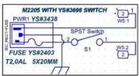
M2205 WITH YS#3696 SWITCH PWR1 YS#3438 W5.1 SPST Switch 2 1 S1 W5.2 2 FUSE YS#2403 T2,0AL 5X20MM
| Section: PowerSupply | |||
| Focus(s): EXMPROSUB | |||
| FCE#: M2106 | Rev#: V02 | Eng: R. Himboaut | Sheet: 4 01 5 |
| Modified: | File:2023/08/Supply.SchDoc | ||
DESIGN HISTORY AND INFORMATION
CHANGE HISTORY
M2106 EXMPROSUB V02
| # | DATE | VER# | PC# | DESCRIPTION OF CHANGE |
| 1 | 21 DEC-2022 | V01 | RELEASED FOR PRODUCTION | |
| 2 | 24-MAY-2023 | V02 | 9958 | One mounting note moved.#3303 22UH Coil footprint updated. |
| 3 | 9957 | Anti Spark circuit added for details see Batemy status section Schematic. | ||
| 4 | Noise reduction circuit added for details sec Power management section Schematic. | |||
| 5 | R05 Value changed from 14K f4995 in 13K f7627. | |||
| 6 | ||||
| 7 | ||||
| 8 | ||||
| 9 | ||||
| 10 | ||||
| 11 | ||||
| 12 | ||||
| 13 | ||||
| # | DATE | VER# | PC# | DESCRIPTION OF CHANGE |
| 1 | ||||
| 2 | ||||
| 3 | ||||
| 4 | ||||
| 5 | ||||
| 6 | ||||
| 7 | ||||
| 8 | ||||
| 9 | ||||
| 10 | ||||
| 11 | ||||
| 12 | ||||
| 13 | ||||
| # | DATE | VER# | PC# | DESCRIPTION OF CHANGE |
| 1 | ||||
| 2 | ||||
| 3 | ||||
| 4 | ||||
| 5 | ||||
| 6 | ||||
| 7 | ||||
| 8 | ||||
| 9 | ||||
| 10 |
THIS SHEET CONTAINS A CHANGE HISTORY LOG, A LIST OF THE POTS & KNOBS AND A LEADS & PINS REFERENCE SECTION.

text_image
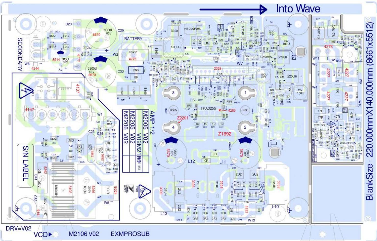
Into Wave SECONDARY D20 3300U 63V C29 5670 BATTERY 3 PIN 4 W2 3300U 63V 5670 C33 DNS OR ES1U ES1J ES1J ES1J ES1J ES1J ES1J ES1J ES1J ES1J ES1J ES1J ES1J ES1J ES1J ES1J ES1J ES1J ES1J ES1J ES1J ES1J ES1J ES1J ES1J ES1J ES1I 4244 4137 4147 W1 M2205 V02 M2206 V02 AMP 1/2 M2005 V02 M2005 V02 M2005 V02 M2005 V02 M2005 V02 M2005 V02 M2005 V02 M2005 V02 M2005 V02 M2005 V02 M2005 V02 M2005 V01 M2005 V02 M2005 V02 M2005 V02 M2005 V02 M2005 V02 M2005 V02 M2005 V02 M2005 V02 M2005 V02 M2005 V02 M2005 V02PCB ASSEMBLY DOCUMENTATION
SPECIAL PRODUCTION NOTES
M2106 EXMPROSUB V02
- Use pizza cutter to separate board from panel.

flowchart
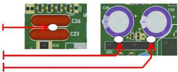
graph TD
    A["ADD RTV"] --> B["BETWEEN C23 AND C26."]
    A --> C["BETWEEN D20 AND C29."]
text_image
C26 C23 R33 C29 + C33 + D20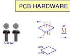
text_image
PCB HARDWARE 2441 2441 H271 430 HG 2195 H2X 2201IMPORTANT!
BEFORE WAVE SOLDER
1_ADD Soldermask dots to the two threaded spacers bottom side of pcb.
AFTER WAVE SOLDER
- Remove the Kapton tape from the spacers.
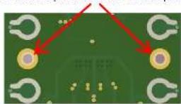
natural_image
Close-up of a green printed circuit board with multiple electronic components and red arrows pointing to specific areas (no readable text or symbols)3 Place Z2201 MYLAR.
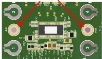
natural_image
Diagram showing a central square with surrounding circular elements and a red arrow pointing to the top-left corner (no text or symbols)4_Place the 4285 Gap pad onto U10 .Handle the pad by the edges only.
flowchart
graph TD
    A[" "] --> B[" "]
    style A fill:#fff,stroke:#000
    style B fill:#fff,stroke:#000
    style_C[" "] --> D[" "]
    style D fill:#fff,stroke:#000
    style_E[" "] --> F[" "]
    style F fill:#fff,stroke:#000
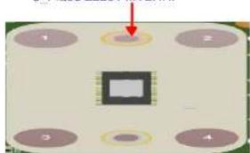
5_Place Z1892 HS on top of U10.
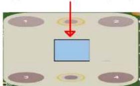
natural_image
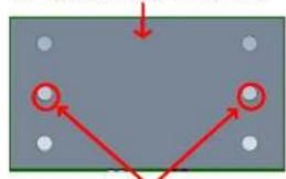
Pure diagram of a rectangular plate with four holes and two red arrows pointing to the center (no text or symbols)6 Secure with two 9441 screws.
Tighten to 8 Inch lbs and make sure heatsink is sitting flat to spacers.
THIS SHEET CONTAINS SPECIAL PRODUCTION NOTES AND A LIST OF PCB HARDWARE PARTS REQUIRED FOR THE BUILD.

DESIGN HISTORY AND INFORMATION
CHANGE HISTORY
M2106 EXMPROSUB V02
| # | DATE | VER# | PC# | DESCRIPTION OF CHANGE |
| 1 | 21 DEC-2022 | V01 | RELEASED FOR PRODUCTION | |
| 2 | 24-MAY-2023 | V02 | 9958 | One mounting note moved.#3303 22UH Coil footprint updated. |
| 3 | ||||
| 4 | 9957 | Anti Spark circuit added for details see Batemy status section Schematic. | ||
| 5 | Noise reduction circuit added for details sec Power management section Schematic. | |||
| 6 | R05 Value changed from 14K f4995 in 13K f7627. | |||
| 7 | ||||
| 8 | ||||
| 9 | ||||
| 10 | ||||
| 11 | ||||
| 12 | ||||
| 13 | ||||
| # | DATE | VER# | PC# | DESCRIPTION OF CHANGE |
| 1 | ||||
| 2 | ||||
| 3 | ||||
| 4 | ||||
| 5 | ||||
| 6 | ||||
| 7 | ||||
| 8 | ||||
| 9 | ||||
| 10 | ||||
| 11 | ||||
| 12 | ||||
| 13 | ||||
| # | DATE | VER# | PC# | DESCRIPTION OF CHANGE |
| 1 | ||||
| 2 | ||||
| 3 | - | |||
| 4 | ||||
| 5 | ||||
| 6 | ||||
| 7 | ||||
| 8 | ||||
| 9 | ||||
| 10 | ||||
| 11 | ||||
| 12 | ||||
| 13 |
THIS SHEET CONTAINS A CHANGE HISTORY LOG, A LIST OF THE POTS & KNOBS AND A LEADS & PINS REFERENCE SECTION.


EXM ProSUB
Bluetooth™
The EXM ProSUB is capable of streaming audio from Bluetooth™ enabled devices and supports wireless 'stereo' pairing between two EXM ProSUBs. In Bluetooth™ stereo mode, the first unit acts as the "Primary," playing the left audio channel and additional units are "Secondary" (playing the right channel). The audio source needs to be connected to the Primary EXM ProSUB unit.
Operation: When the EXM ProSUB is powered on, Bluetooth™ is disabled by default. To connect a device, tap the Bluetooth™ button. If a device has been previously connected, it will attempt to reconnect. If a wireless stereo connection was used, both EXM ProSUB units will try to re-establish the wireless stereo connection (the same Primary/Secondary roles re-established).
Pairing: Press the Bluetooth™ button down and hold for 4 seconds, then release.
Status: The blue LED indicates the status of the Bluetooth™ connection, please refer to the chart in the Owner's Manual for more detail.
Level: Streamed music's volume can be changed via the connected Bluetooth™ device.
Stereo Mode: Wireless stereo playback is supported between two EXM ProSUBs. One acts as the Primary unit while another acts as a Secondary unit. The Primary unit plays the left audio channel while the Secondary unit plays the right. The source device only connects to the Primary unit, not the Secondary.
To enable Stereo Mode, double tap the Bluetooth™ button on the EXM ProSUB used as the Primary unit (left), then double tap the Bluetooth™ button on the secondary EXM ProSUB (right). The first unit double tapped becomes the Primary unit (left).
New devices can still be paired to a Primary unit if it's in Stereo Mode. Pairing a device to an EXM ProSUB that is in Secondary mode will end the stereo wireless connection.
Button Operation:
Single Tap: Enables Bluetooth™
Double Tap: Enter Stereo Mode
Press and Hold (4 seconds): Enter Pairing Mode
Press and Hold (8 seconds): Disables Bluetooth™
Range: The EXM's Bluetooth™ operating range is rated for 10 meters (33 feet) line of sight. The link's quality can be affected by excess wireless traffic in the 2.4 GHz bandwidth or structures between the Bluetooth™ unit and the streaming device.
Note: When connected with Bluetooth™, ALL audio is streamed from your device. If you don't want the streaming music to be interrupted, turn off 'notifications' on your device.
Controls & Input/Output
Input Jacks: The source should go directly to the EXM ProSUB and then looped to the full-range loudspeakers using the High Pass Output jacks, this ensures an ideal crossover to the full-range loudspeakers. These jacks can be fed with mono or stereo. For mono, either the Left or Right jack can be used and if using stereo signals, the mono output sums the Left and Right signals.
Note: stereo separation is maintained for signals leaving the High Pass Output jacks.
Sub Level Control: This sets the amount of bass added to the system and adjusts for the relative sensitivity of the companion full-range speakers.
High Pass Output Jacks: These jacks eliminate the need for an external crossover, use these to feed the input of your powered full-range loudspeakers. The output signal of these XLR jacks has the audio below 100 Hz removed.
Full Range Output Jack: This jack can be used to send full-range signal (mono/summed) to additional EXM ProSUBs or other powered enclosures that don't require a stereo source.
Protection and Indicators: This circuitry helps prevent amplifier clipping, over excursion and protects the amplifier and/or voice coil from overheating.
Battery & Charging
Battery Status Indicators: A series of four LEDs indicate the approximate charge level. The upper green LED is illuminated if there's greater than 75% charge. The red LED indicates if the battery is critically low (approx 15% remaining) and needs immediate charging.
Note: The indicators will be engaged only when the power switch is turned on.
Charging Indicator: When AC is connected, the charging indicator will be turned on. Green indicates fully charged, red indicates the unit is charging.
Charging: To charge, plug into an AC power source using the included power cord. The charging LED indicates the charging status; if all of the status LEDs are lit, there is still possibly additional charging time required. The EXM ProSUB can be safely left connected to AC power for charging indefinitely.
The EXM ProSUB will not charge when the temperature is below 0^ C or above 45^ C. If it's going to be stored unused for a long period of time (+6 months) it is advisable to plug it in to charge up the battery periodically. If stored for a long period of time unused and not been maintained, it is suggested to connect the charger and leave it plugged in for approximately 24 hours.

THIS UNIT CAN BE OPERATED WHILE CHARGING!
To get the full Owner's Manual please visit our website at
http://www.yorkville.com/manuals/ or, if you need a printed version call 905-837-8777
REAL Gear.
REAL People.
Canada
Voice: (905) 837-8481
Fax: (905) 837-8746
U.S.A.
Voice: (716) 297-2920
Fax: (716) 297-3689

Yorkville
www.yorkville.com
Yorkville Sound
550 Granite Court
Pickering, Ontario
L1W-3Y8 CANADA
Yorkville Sound Inc.
4625 Witmer Industrial Estate
Niagara Falls, New York
14305 USA