DALI128 KNX - Smart home gateway STEINEL - Free user manual and instructions
Find the device manual for free DALI128 KNX STEINEL in PDF.

| Product type | DALI-KNX home automation gateway |
| Brand | Steinel |
| Model | DALI128 KNX |
| Supply voltage | AC 110-240 V, 50/60 Hz or DC 110-240 V |
| Power consumption | Max. 3 W |
| Bus type | KNX TP 256 |
| KNX bus voltage | DC 21-32 V SELV |
| KNX bus current | 4.5-5.0 mA |
| DALI protocol | EN 62386 (DALI-2) |
| Max number of DALI participants | 64 per system, 128 total (dual model) |
| Number of DALI groups | 32 per system |
| Ambient temperature | -5 to +45 °C |
| Mounting type | On DIN rail (EN 60715) |
| Width | 72 mm (4 modules) |
| Connections | Screw terminals, max. torque 0.8 Nm |
| Main functions | HCL, CT mode, short-circuit/overload/surge protection, hour counter, individual/group/broadcast addressing, 16 lighting scenes, hot swap, etc. |
| Commissioning | Via ETS 5.7.7+ or 6.1.0+ and DCA |
| Security | KNX Data Secure, device certificate, KNX/DALI isolation |
| Cleaning | With a dry cloth. Do not use aggressive cleaning agents. |
| Warranty | Statutory warranty. Manufacturer: Steinel GmbH |
| Repairability | Repairs must be carried out by a qualified electrician. |
Frequently Asked Questions - DALI128 KNX STEINEL
User questions about DALI128 KNX STEINEL
0 question about this device. Answer the ones you know or ask your own.
Ask a new question about this device
Download the instructions for your Smart home gateway in PDF format for free! Find your manual DALI128 KNX - STEINEL and take your electronic device back in hand. On this page are published all the documents necessary for the use of your device. DALI128 KNX by STEINEL.
USER MANUAL DALI128 KNX STEINEL
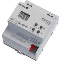
DALI Gateway DALI64 KNX-S
Art.-Nr. 089207
DALI Gateway DALI128 KNX-S
Art.-Nr. 089214

Inhaltsverzeichnis
Operating instructions
DALI Gateway DALI64 KNX-S
Art. no. 089207
DALI Gateway DALI128 KNX-S
Art. no. 089214

Table of contents
1 Safety instructions .... 3
2 Function.... 3
3 Operation.... 5
4 Information for electrically skilled persons.... 8
4.1 Mounting and electrical connection.... 8
4.2 Commissioning 9
5 Appendix.... 12
5.1 Technical data.... 12
5.2 Troubleshooting 13
5.3 Warranty 14
1 Safety instructions

Electrical devices may be mounted and connected only by electrically skilled persons.
Serious injuries, fire or property damage are possible. Please read and follow the manual fully.
Danger of electric shock. Always disconnect before carrying out work on the device or load. In so doing, take all the circuit breakers into account, which support dangerous voltages to the device and or load.
DALI is an FELV (functional extra-low voltage). On installing, ensure safe isolation between KNX and DALI and mains voltage. A minimum distance of at least 4 mm must be maintained between bus conductors and DALI/mains voltage cores.
These instructions are an integral part of the product, and must remain with the end customer.
2 Function
System information
This device is a product of the KNX system and complies with the KNX directives. Detailed technical knowledge obtained in KNX training courses is a prerequisite to proper understanding.
The function of this device depends upon the software. Detailed information on loadable software and attainable functionality as well as the software itself can be obtained from the manufacturer's product database.
The device can be updated. Firmware can be easily updated with the STEINEL KNX Service App (additional software).
The device is KNX Data Secure capable. KNX Data Secure offers protection against manipulation in building automation and can be configured in the ETS project. Detailed technical knowledge is required. A device certificate, which is attached to the device, is required for safe commissioning. During mounting, the device certificate must be removed from the device and stored securely.
Planning, installation and commissioning of the device are carried out with the aid of the ETS, version 5.7.7 and higher or 6.1.0.
Intended use
- Controlling of luminaires and other applications with DALI operating device in KNX installations, e.g. electronic ballast
- Mounting on DIN rail according to EN 60715 in distribution boxes
Product characteristics
- DALI-2 certified
-
Control of up to 64 DALI devices in up to 32 groups ("1-fold" device variant)
-
Control of max. 2x 64 DALI devices in max. 2x 32 groups ("2-fold" device variant)
- Setting the colour temperature or light colour (RGB, RGBW) for luminaires with DALI Device Type 8 in accordance with IEC 62386-209
– Short-circuit, overload and overvoltage protected - Operating hours counter
– Automatic colour wheel sequence or brightness sequence
– HCL mode (Human Centric Lighting), automatic daytime colour temperature profile - CT (Colour Transition) mode, automatic daytime colour profile
- Suitable for operation of emergency lighting systems with DC voltage
– Individual, group or central addressing - 16 light scenes per DALI system
- Reading out of DALI device states via KNX, e.g. brightness or luminaire error
- Manual operation of the DALI groups, single devices or central (broadcast) separately for each DALI system
- Restraint or disabling functions
- Feedback of switching state and brightness value in bus and manual mode
– Collective feedback
– Central switching and dimming function - Disabling function for each DALI group or each single device
- Separate switch-on and switch-off delay
– Staircase lighting timer with run-on time
– Online or offline project design of the DALI devices with ETS-DCA - Standby switch-off of the DALI devices
– An individual DALI device of the same type can be exchanged during operation without software
Delivery state: Construction site mode, manual operation is enabled. The connected DALI operating devices of both DALI systems can be controlled via the keypad via the broadcast function.
The complete functionality of the DALI system can only be ensured if DALI-2 operating device is used exclusively.
A complete list of DALI-2 operating and control devices can be found here: https://www.dali-alliance.org/products
3 Operation
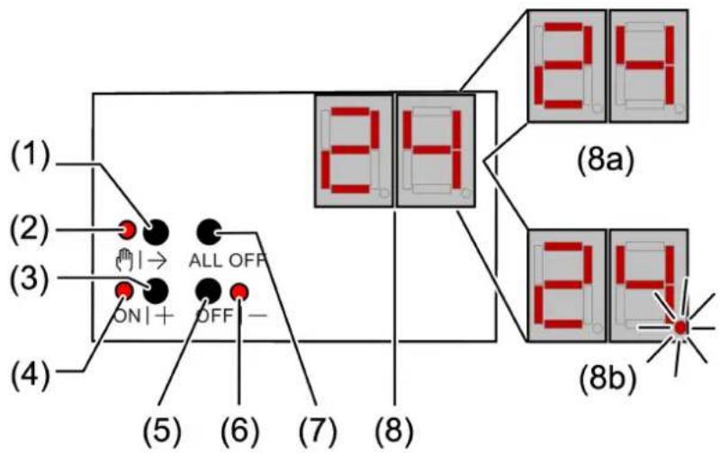
Figure 1: DALI Gateway control panel, 1fold
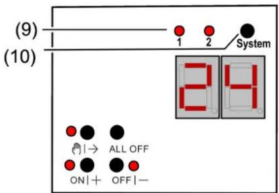
Figure 2: DALI Gateway control panel, 2fold
(1) 📋→ button – Manual operation
(2) LED ⬇|→ – On: Continuous manual mode active
LED ⬇|→ – Flashing: Temporary manual mode is active
(3) ON|+ button - switch on or increase brightness
(4) LED ON|+ – On: DALI device or group switched on, Brightness 1...100%
(5) OFF|- button - switch off or reduce brightness
(6) LED OFF|-- On: DALI device or group switched off, Brightness 0%
(7) Button ALL OFF – Switch off all DALI devices
(8) Display of DALI number
(8a) Display of DALI group
(8b) Display of the short address of the individual DALI devices (1...64)
(9) LED of the active DALI system lights up in manual mode or after pressing the change-over button (only with "2fold" device variant)
(10) Change-over button for DALI systems 1 and 2 (only with "2fold" device variant)
If the display (8) shows bc (broadcast operation), all devices of a DALI system are controlled jointly. This is done in the following operating conditions.
– The device is not programmed
- Set to master control in the KNX configuration
– In bus mode, broadcast is additionally configured and active
When operating the DALI devices with the keypad, the device differentiates between short and long actuation.
– Short: Pressing for less than 1 second
- Long: Pressing for between 1 and 5 seconds
Change-over system 1 and system 2
In the case of the "2fold" device variant, the change-over button (10) can be used to switch between an operation of DALI systems 1 and 2. This is possible either while the device is in operation or during active temporary or permanent manual operation.
Only the selected DALI system is ever operated via the keypad of the manual control. The LEDs (9) signal the DALI system effective for manual operation.
Switching on temporary manual operation mode
Operation using the button field is programmed and not disabled.
■ Press the Ⓞ→ (1) button briefly.
Display (8) shows the first group number, short address or bc, LED (2) flashes. With the "2fold" device version, the LED (9) of the last operated DALI system lights up.
After 5 seconds without a button actuation, the device returns automatically to bus mode.
Switching on/off the permanent manual mode
Operation using the button field is programmed and not disabled.
■ Press the Ⓜ|→ (1) button for at least 5 seconds.
LED ^TM (2) is illuminated, display (8) shows the first group number, short address or bc.. Permanent manual operation is switched on. With the "2fold" device version, the LED (9) of the last operated DALI system lights up.
- or in case of repeated actuation for at least 5 seconds -
LED Ⓞ|→ (2) is off, indication (8) is off, bus mode is switched on.
Operating DALI devices
The device is in permanent or temporary manual operation mode.
Press Ⓞ→ (1) button briefly as many times as necessary until the desired DALI number is indicated (8).
■ Operate output with ON|+ (3) button or OFF|- (5) button.
Short: switch on/off.
Long: dim brighter/darker.
Release: Stop dimming.
The LEDs ON|+ (4) and OFF|- (6) indicate the status.
The display (8) shows first the numbers of the available DALI groups (8a), followed by the individual addresses of the DALI devices (8b).
Switch off all DALI devices
The device is in permanent manual operation mode.
■ Press the ALL OFF button (7).
Disabling/enabling individual DALI devices or groups
The device is in permanent manual operation mode and the lock is released.
Press (1) button briefly as many times as necessary until the desired DALI number is indicated (8).
■ Press the buttons ON|+ (3) and OFF|- (5) simultaneously for at least 5 seconds.
The selected DALI number flashes on the display (8).
DALI device or group is blocked.
- or in case of repeated actuation -
The display (8) no longer flashes.
DALI device or group is enabled.
■ Activate bus mode (see section Switching the permanent manual mode on/off).
DALI devices blocked via manual operation can be operated in manual mode.
4 Information for electrically skilled persons
4.1 Mounting and electrical connection

DANGER!
Electric shock when live parts are touched.
Electric shocks can be fatal.
Always disconnect device before carrying out work on it. For this, switch off all corresponding circuit breakers, secure against being switched on again and check that there is no voltage. Cover up adjacent live parts.
Mount device
■ Mount device on DIN rail.
Connect device
Control cable: appropriate type, cross-section and routing for the specifications for 230 V cables. DALI and mains voltage wires can be run together in a cable, e.g. NYM 5x1.5 mm ^4 .
■ The DALI control voltage is a functional extra-low voltage (FELV). When installing, perform the installation in such a way that when an area is disconnected, the lines carrying both the DALI and also the mains voltage are disconnected.
■ If multiple circuit breakers supply dangerous voltages to the device or load, couple the circuit breakers or label them with a warning to ensure tripping.
■ DALI participants from some manufacturers have expanded functions and can be controlled, for example, via mains voltage on the DALI connection. When existing DALI installations are refitted, remove all corresponding operator controls.
■ Connect device as shown in the connection example (see figure 3)
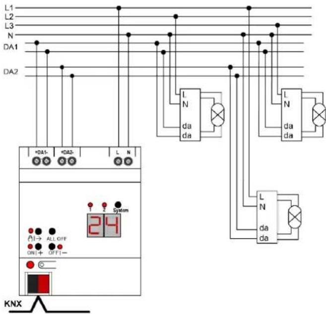
Figure 3: DALI gateway connection example, 2fold
■ Attach the cover cap to the bus cable connection as protection against hazardous voltages.
If the display (8) shows Er (error), an installation fault occurred that causes mains voltage to reach the DALI cable. In this case disconnect the device and the DALI devices from mains voltage and disconnect bus voltage. Correct installation.
4.2 Commissioning
The device can be put into operation, after mounting of the device and connection of the bus line, the mains supply and the DALI cables. The following procedure is generally recommended...
Commissioning the device
■ Switch on the mains supply of the gateway.
■ Switch on the bus voltage.
Voltage check: When the programming button is pressed, the red programming LED must light up.
■ Configure and program the physical address with the help of the ETS
■ Download the application program using the ETS.
■ Commission the DALI system using commissioning software (DCA).
■ Download the application program using the ETS again.
The gateway is ready for operation.
i It is not explicitly necessary to carry out DALI commissioning and reprogram the application program if the gateway has been integrated into an existing DALI installation (e.g. when replacing a device of the same type) and contin-
ues to be used with an unchanged DALI configuration (same short addresses, device types, group assignments, etc.). This is the case, for example, if a device is copied unchanged in the ETS project design or a configuration template is imported.
No ETS programming is possible if no mains voltage supply is connected.
Safe-state mode
If the device does not work properly - for instance as a result of errors in the project design or during commissioning - the execution of the loaded application program can be halted by activating the safe-state mode. In safe-state mode it is not possible to control the DALI operating devices via the KNX or by manual operation. The gateway remains passive in safe-state mode, since the application program is not being executed. Only the system software is still functional so that the ETS diagnosis functions and also programming of the device continue to be possible.
Activating safe-state mode
There are two options for activating the safe state mode.
Option 1:
■ Switch off the mains voltage supply.
■ Wait approx. 10 seconds.
■ Press and hold down the programming button.
■ Switch on the mains supply. Release the programming button only after the programming LED starts flashing slowly.
The safe-state mode is activated.
Option 2:
Prerequisite: The mains voltage supply must be switched on without interruption.
■ Switch off the bus voltage or disconnect the bus terminal.
■ Press and hold down the programming button.
■ Switch on the bus voltage or attach the bus terminal. Release the programming button only after the programming LED starts flashing slowly.
The safe-state mode is activated.
Even in safe-state mode, a brief press of the programming button can switch the programming mode on or off as usual as long as the bus power supply is switched on. The programming LED then stops flashing, even though safe-state mode is still active.
Deactivating safe-state mode
■ Switch off the mains voltage supply (wait approx. 10 s), or
■ Perform the ETS programming operation,
or
■ Cause bus voltage failure.
Master reset
The master reset restores the basic device settings (physical address 15.15.255, firmware remains in place). The device must then be recommissioned with the ETS. Manual operation is possible.
In secure operation: A master reset deactivates device security. The device can then be recommissioned with the device certificate.
Performing a master reset
Precondition: The safe-state mode is activated.
■ Press and hold down the programming button for > 5 s.
The programming LED flashes quickly.
The device performs a master reset, restarts and is ready for operation again after approx. 5 s.
Restoring the device to factory settings
The device can be reset to factory settings with the STEINEL KNX Service App. This function uses the firmware contained in the device that was active at the time of delivery (delivered state). Restoring the factory settings causes the device to lose its physical address and configuration.
5 Appendix
5.1 Technical data
KNX
KNX medium TP 256
KNX commissioning mode S mode
Rated voltage KNX DC 21 ... 32 V SELV
Current consumption KNX 4.5 ... 5.0 mA
Connection type for bus Device connection terminal
Supply
Rated voltage AC 110 ... 240 V \~
Mains frequency 50 / 60 Hz
Rated voltage DC 110 ... 240 V
Power loss max. 3 W
DALI
Rated voltage DALI DC 16 V (typ.)
Output current per DALI system Typ. 128 mA, max. 250 mA for short periods
Guaranteed bus current per DALI system 148 mA
Number of DALI subscribers Max. of 64 per DALI system
DALI transmission rate 1.2 kBit/s
DALI protocol EN 62386
Cable type
DALI cable length (see figure 4)
Sheathed cable 230 V, e. g. NYM
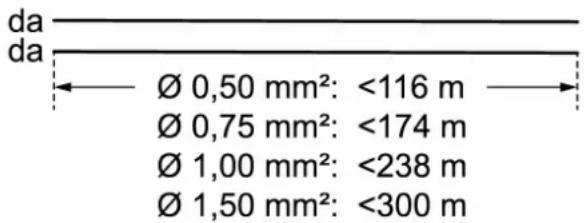
Figure 4: DALI cable length
Ambient conditions
Ambient temperature -5 ... +45°C
Storage temperature -5 ... +45°C
Transport temperature -25 ... +70°C
Clampable cable cross-sections (see figure 5)
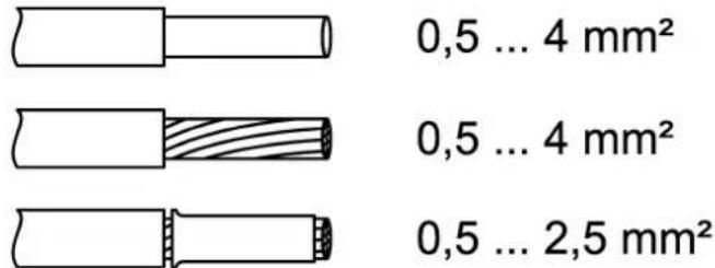
0,5 ... 4 mm ^2
0,5 ... 4 mm ^2
0,5 ... 2,5 mm²
Figure 5: Clampable cable cross-sections
Installation width 72 mm / 4 HP
Connection mode Screw terminal
Connection torque, screw terminals max. 0.8 Nm
5.2 Troubleshooting
Indication shows "Er", connected DALI devices have no function, no operation possible
Cause: Mains voltage on DALI cable.
Installation error. Disconnect device and connected DALI devices from mains voltage and disconnect bus voltage. Correct installation.
Indication shows "bc" in manual mode, control of individual luminaires not possible.
Cause: The device is not programmed or is programmed for central control.
Check device status or change operation from broadcast to group or individual control.
Individual DALI devices have no function
Cause 1: Load is defective, e.g. lamp.
Exchange load.
Cause 2: DALI device is defective.
Exchange defective device.
Switch on voltage.
Press ⬇|→ and ALL OFF buttons together for at least 10 seconds.
The device detects the exchanges DALI device and loads in the necessary data. The display (8) shows LE.
Simultaneous exchange of multiple DALI devices is only possible with commissioning software (DCA) and project data.
DALI groups or single devices cannot be operated
Cause 1: DALI groups or single devices disabled via bus or manual operation.
Cancel disabling.
Cause 2: Permanent manual mode is switched on.
Deactivate permanent manual operation mode.
Cause 3: Application programme has been stopped; programming LED is flashing.
Perform reset: Disconnect device from bus, switch on again after approx. 5 seconds.
Cause 4: Application programme is not loaded.
Check and correct the programming.
5.3 Warranty
We reserve the right to make technical and formal changes to the product in the interest of technical progress.
We provide a warranty as provided for by law.
STEINEL GmbH
Dieselstraße 80-84
33442 Herzebrock-Clarholz
Telefon +49 5245 448 0
www.steinel.de
product@steinel.de
DALI Gateway DALI64 KNX-S
Núm. de art. 089207
DALI Gateway DALI128 KNX-S
Núm. de art. 089214

Índice
DALI Gateway DALI64 KNX-S
Réf. 089207
DALI Gateway DALI128 KNX-S
Réf. 089214

Sommaire
Court : activation/désactivation.
Activer le mode Safe State
Désactiver le mode Safe State
DALI Gateway DALI64 KNX-S
N. art. 089207
DALI Gateway DALI128 KNX-S
N. art. 089214

Indice
DALI Gateway DALI64 KNX-S
Art. nr. 089207
DALI Gateway DALI128 KNX-S
Art. nr. 089214

Inhoudsopgave
Oorzaak 2: DALI-deelnemer is defect.
DALI Gateway DALI64 KNX-S
Art.-nr. 089207
DALI Gateway DALI128 KNX-S
Art.-nr. 089214

Innholdsfortegnelse
Slipp: Dimming stopper.