
P640 KNX - Power Supply STEINEL - Free user manual and instructions
Find the device manual for free P640 KNX STEINEL in PDF.

| Product type | KNX power supply |
| Brand | Steinel |
| Model | P640 KNX |
| Rated voltage | AC 220-240 V ~ (range 180-264 V AC) |
| Mains frequency | 50 / 60 Hz |
| Bus output voltage | DC 28-31 V SELV |
| Output current (total) | 640 mA (ref. 084882) or 1280 mA (ref. 085667) |
| Short-circuit current | Max 1.5 A (640 mA) or max 3 A (1280 mA) |
| DC 30 V output | Yes, for powering additional devices |
| Signaling contact | Yes, potential-free (AC 12-230 V / DC 2-30 V, 5 mA-2 A) |
| Ambient temperature | -5 to +45 °C |
| Storage temperature | -25 to +70 °C |
| Relative humidity | Max 93% (non-condensing) |
| Width (modules) | 72 mm / 4 modules (640 mA) or 108 mm / 6 modules (1280 mA) |
| Connection type | Screw terminals for stranded wires with ferrule 0.5-2.5 mm² |
| Efficiency | Approx. 87% (640 mA) or 86% (1280 mA) |
| Power loss | Max 2.9 W (640 mA) or max 6.4 W (1280 mA) |
| Parallel operation | Possible only for 640 mA version |
| Mounting | On DIN rail according to EN 60715 |
| Protection | Short-circuit, overvoltage, no-load proof |
| Approval | KNX TP256 device |
| Warranty | Legal warranty, manufacturer: STEINEL GmbH |
Frequently Asked Questions - P640 KNX STEINEL
User questions about P640 KNX STEINEL
0 question about this device. Answer the ones you know or ask your own.
Ask a new question about this device
Download the instructions for your Power Supply in PDF format for free! Find your manual P640 KNX - STEINEL and take your electronic device back in hand. On this page are published all the documents necessary for the use of your device. P640 KNX by STEINEL.
USER MANUAL P640 KNX STEINEL
Power Supply P640 KNX
Art.-Nr. 084882
Power Supply P1280 KNX
Art.-Nr. 085667
Inhaltsverzeichnis
Operating instructions
Power Supply P640 KNX
Art. no. 084882
Power Supply P1280 KNX
Art. no. 085667
Table of contents
1 Safety instructions .... 3
2 Device components 3
3 Function.... 4
4 Operation.... 5
5 Information for electrically skilled persons.... 6
5.1 Mounting and electrical connection.... 6
6 Technical data 10
7 Warranty 11
1 Safety instructions

Electrical devices may be mounted and connected only by electrically skilled persons.
Serious injuries, fire or property damage are possible. Please read and follow the manual fully.
Danger of electric shock. During installation and cable routing, comply with the regulations and standards which apply for SELV circuits.
These instructions are an integral part of the product, and must remain with the end customer.
2 Device components

Figure 1: View
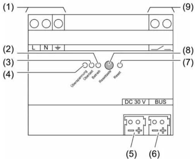
Figure 2: 1280 mA voltage supply – view
(1) Connection of mains
(2) LED Betrieb, green
On: Normal operation
Flashes: Overload or overvoltage
Off: No mains voltage or internal error
(5) Output DC 30 V
(6) Output Bus for KNX bus line
(7) LED Reset, red
Flashes rapidly 2.5 Hz: Reset for 20 seconds
Flashes slowly 0.25 Hz: Permanent reset
(8) Button Reset
Acknowledge the diagnostic message: Press briefly, < 0.5 seconds
Switch off the KNX bus line for 20 seconds: Press between 2...4 seconds
Permanently switch off the KNX bus line: Press longer than 4 seconds
Terminate the permanent reset: Press the button
(9) Signal contact for diagnostic message
Closed: Normal operation
Open: After overload, overvoltage or in case of a KNX power failure
3 Function
System information
This device is a product of the KNX system and complies with the KNX directives. Detailed technical knowledge obtained in KNX training courses is a prerequisite to proper understanding.
Intended use
– Supplying KNX devices with bus voltage
– Supplying devices with direct current
- Mounting on DIN rail according to EN 60715 in sub-distribution unit
Product characteristics
- Output with integrated inductance for supplying KNX bus lines
- DC 30 V output for supplying additional devices
– Nominal current can be subdivided to outputs as desired - Reset button
- Short-circuit proof
-
Overvoltage proof
-
No-load proof
- Suitable for operation in systems with emergency power supply
– Potential-free signal contact for operating and diagnostic message - Two identical voltage supplies can be connected in parallel (with the version 640 mA)
4 Operation
Acknowledging the diagnostic message
After detecting a overvoltage or a short circuit the LED and the signal contact signal the event until the message is acknowledged.
■ Press the Reset button for less than 0.5 seconds.
LED functions and signal contact
| LEDBetrieb (2), green | LEDÜberlast (3), red | LEDÜberspan-nung (4), yellow | LEDReset (7), red | Signal contact (9) | |
| Normal operation | on off off off closed | ||||
| Reset for 20 seconds | on off off flashes | 2.5 Hz | closed | ||
| Permanent reset | on off off flashes | 0.25 Hz | closed | ||
| Overvoltage | flashes0.5 Hz | off on (until the message is acknowledged) | message is acknowledged) | off open (until the message is acknowledged) | |
| Overload, short-circuit | flashes0.5 Hz | on (until the message is acknowledged) | off off open (until the message is acknowledged) | ||
| KNX voltage failed / internal error | off off off open | ||||
In normal operation, control of the voltage supply is not necessary. The button (8) is recessed and thus prevents that it is inadvertently actuated in operation.
Reset function and Reset button
When a bus segment is reset, the output voltage of the voltage supply is switched off. At the same time the bus line is short-circuited so that all connected bus devices are disconnected from the bus voltage.
Resetting the bus line for 20 seconds
■ Press the Reset button (8) between 2 ... 4 seconds.
The bus line is short-circuited for 20 seconds.
The LED Reset (7) flashes quickly.
After 20 seconds the bus voltage is switched on again and the LED Reset switches off.
Permanently resetting the bus line
■ Press the Reset button (8) for more than 4 seconds.
The bus line is short-circuited.
The LED Reset (7) flashes slowly.
Terminating the permanent reset
Prerequisite: The bus line is permanently reset, the LED Reset (7) flashes slowly.
■ Press the Reset button (8).
The bus voltage is switched on again and the LED Reset switches off.
5 Information for electrically skilled persons

DANGER!
Electric shock when live parts are touched.
Electric shocks can be fatal.
Before working on the device, disconnect all corresponding circuit breakers from the supply voltage, secure against being switched on again and check that there is no voltage!
5.1 Mounting and electrical connection
Mount device
Observe the temperature range. Ensure sufficient cooling.
■ Mount the device on DIN rail. The terminals for the mains connection (1) must be at the top.
Connecting the device to mains voltage and bus

Figure 3: Wiring example – mains voltage and bus line
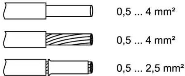
Figure 4: Clampable conductor cross-section
■ Connect the mains voltage to the terminals L and N (1).
■ Connect the protective conductor PE to the terminal 12 .
■ Connect the KNX bus line to output Bus (6).
■ Install the cover to protect the bus connection against hazardous voltages in the connection area.
The total load of the outputs can be subdivided as desired. Do not exceed the total rated current.
Do not connect any other products to the bus output. This might influence the bus communication.
If required, an identical voltage supply can be connected in parallel for the device variant 640 mA.
Connecting the diagnostic analyser
The voltage supply signals overvoltage, overload, short circuit and KNX voltage failure using a floating contact (9). A monitoring device can detect the switching status and forward it for diagnostic purposes.
The signal output serves only for signalling purposes and may not be used as a load output.
A signal lamp, a signal relay or, e.g., a KNX binary input connected to a KNX bus line can be used as monitoring device.
■ Connect the signalling device according to the connection example (see figure 5).

Figure 5: Application example – signal lamp for optical operating display
■ Connect the KNX binary input according to the connection example (see figure 6).
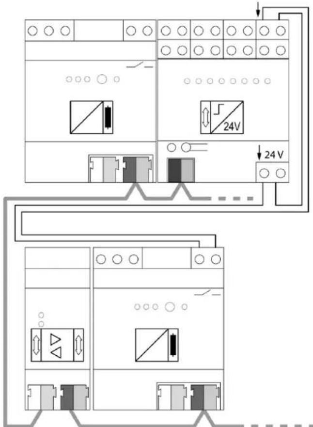
Figure 6: Application example – KNX binary input on main line for detecting and centrally signalling diagnostic messages
i Observe the wiring! Install the cables for the signal contact such that no loops are created. During operation loops can cause interference voltages to be coupled into.
The signal contact indicates a power failure on the KNX line. When voltage supplies are connected in parallel, the signaling contact opens only if both voltage supplies are faulty or switched off (e.g. due to failure of the mains voltage on both devices).
In this case too, the green operation LED will not extinguish until both power supplies are switched off.
Operation with emergency power systems
The voltage supply can be used in combination with centrally supplied emergency power systems. In this way, the function of the KNX system and the control of the most important functions can be ensured in emergency operation.
i Statutory and standard specifications for emergency power and emergency lighting systems vary from country to country. In any event, the user / technical planner must check whether the specific specifications are observed.
Cable lengths
For KNX line segments and power supplies the following rules apply:
- Bus line length per line segment: Max. 1000 m
- Bus line length between voltage supply and KNX bus subscriber: Max. 350 m
- Bus line length between two KNX bus subscribers: Max. 700 m
6 Technical data
Rated voltage AC 220 ... 240 V \~
The device is operable in the range of
180 V AC ... 264 V AC.
Power loss (max. load on all outputs)
Art. no. 084882 max. 2.9 W
Art. no. 085667 max. 6.4 W
Efficiency
Art. no. 084882 approx. 87%
Art. no. 085667 approx. 86%
Rated voltage DC DC 240...250 V
KNX
KNX medium TP256
Bus output voltage DC 28 ... 31 V SELV
Output current
Art. no. 084882 640 mA (all outputs)
Art. no. 085667 1280 mA (all outputs)
Short-circuit current
Art. no. 084882 max. 1.5 A
Parallel operation with identical voltage
supply
Art. no. 084882 Yes
Art. no. 085667 No
Output DC 30 V
Output voltage DC 30 V
Signal output
Switching voltage AC AC 12 ... 230 V\~
Switching voltage DC DC 2 ... 30 V
Switching current 5 mA ... 2 A
Connection mode Device connection terminal
Finely stranded with conductor sleeve 0.5 ... 2.5 mm ^4
7 Warranty
We reserve the right to make technical and formal changes to the product in the interest of technical progress.
We provide a warranty as provided for by law.
STEINEL GmbH
Dieselstraße 80-84
33442 Herzebrock-Clarholz
Telefon +49 5245 448 0
www.steinel.de
info@steinel.de
Power Supply P640 KNX
Núm. de art. 084882
Power Supply P1280 KNX
Núm. de art. 085667
Índice
Power Supply P640 KNX
Réf. 084882
Power Supply P1280 KNX
Réf. 085667
Sommaire
Power Supply P640 KNX
N. art. 084882
Power Supply P1280 KNX
N. art. 085667
Indice
Power Supply P640 KNX
Art. nr. 084882
Power Supply P1280 KNX
Art. nr. 085667
Inhoudsopgave
Knippert: overbelasting of overspanning
De led Reset (7) knippert snel.
Power Supply P640 KNX
Art.-nr. 084882
Power Supply P1280 KNX
Art.-nr. 085667
Innholdsfortegnelse
Bilde 5: Brukseksempel – Signallampe for optisk driftsindikering