DCT412 - Video camera DEWALT - Free user manual and instructions
Find the device manual for free DCT412 DEWALT in PDF.

User questions about DCT412 DEWALT
0 question about this device. Answer the ones you know or ask your own.
Ask a new question about this device
Download the instructions for your Video camera in PDF format for free! Find your manual DCT412 - DEWALT and take your electronic device back in hand. On this page are published all the documents necessary for the use of your device. DCT412 by DEWALT.
USER MANUAL DCT412 DEWALT
English (original instructions)
natural_image
Line drawing of a handheld electric vehicle (no text or symbols)Figure 2
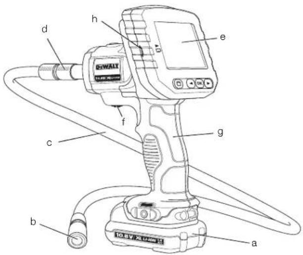
Figure 3
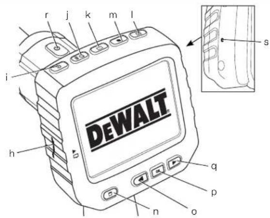
Figure 4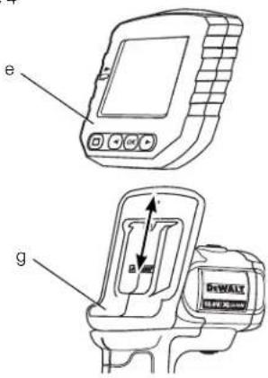 | Figure 5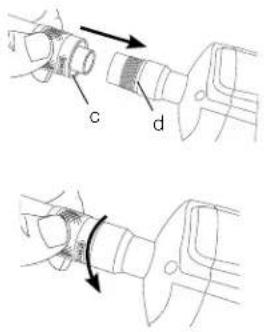 |
Figure 6A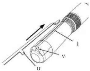 | Figure 6B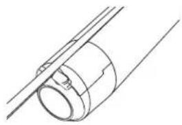 |
Figure 7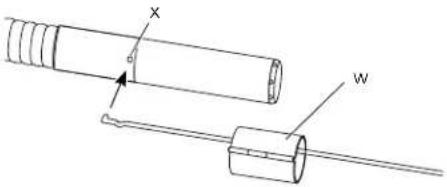 | Figure 8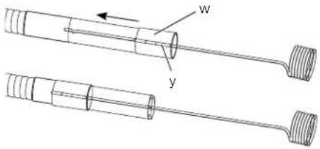 |
Figure 9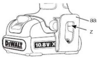 | Figure 10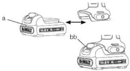 |
TRÅDL∅ST INSPEKTIONSKAMERA DCT410, DCT411, DCT412
Tillykke!
natural_image
3D rendering of a wall-mounted cable or wire connection with a square component (no text or symbols visible)natural_image
3D rendering of a cylindrical pipe connected to two cables in an indoor setting (no text or symbols visible)DANSK
natural_image
3D rendering of a ceiling-mounted electrical cable with exposed wiring and a rectangular component (no text or symbols)Ændring af sprog [LANGUAGES]
natural_image
Pure electrical circuit lines without any symbolsnatural_image
3D rendering of a cylindrical pipe connected to a wall, with visible cables and no text or symbolsnatural_image
3D rendering of a mechanical or electrical component with wires and a central block (no visible text or symbols)You have chosen a DEWALT tool. Years of experience, thorough product development and innovation make DEWALT one of the most reliable partners for professional power tool users.
Technical Data
| DCT410 | DCT411 | DCT412 | |
| Voltage | V_cc | 10.8 | 10.8 |
| Type 111 | |||
| Battery Type | Li-Ion Li-Ion Li-Ion | ||
| Camera cable diameter | mm | 17 | 9 |
| Cable length | m 0.9 | 0.9 0.9 | |
| Resolution | dpi 320 x 480 | 320 x 480 | 320 x 480 |
| Screen size | mm 69 x 50 | 69 x 50 | 69 x 50 |
| Weight (without battery pack) kg | 0.77 | 0.69 | |
| Battery pack | DCB121 | DCB123 | |
| Battery type | LI-Ion | LI-Ion | |
| Voltage | V_DC | 10.8 | 10.8 |
| Capacity | A_h | 1.3 | 1.5 |
| Weight | kg | 0.2 | 0.2 |
| Charger | DCB100 | DCB105 | |||
| Mains voltage V_sc | 230 | 230 | |||
| Battery type | Li-Ion | Li-Ion | |||
| Approx. charging time | min | 40(1.3 Ah battery packs) | 40(1.5 Ah battery packs) | 30(1.3 Ah battery packs) | 30(1.5 Ah battery packs) |
| Weight | kg | 0.3 | 0.49 | ||
Fuses
| Europe | 230 V tools | 10 Amperes, mains |
| U.K. & Ireland | 230 V tools | 3 Amperes, in plugs |
![DEWALT DCT412 - Ændring af sprog [LANGUAGES] - 2](/content/2026/04/690649/images/3e3b5211ad584fa87406994965fe298eeedc61a67448463e8e8c47cb278b61c7.jpg)
WARNING: This is a Class A product. In a domestic environment this product may cause radio interference in which case the user may be required to take adequate measures.
![DEWALT DCT412 - Ændring af sprog [LANGUAGES] - 3](/content/2026/04/690649/images/0d1697d90e96208a7c74985edefb192df77d3b8faf7530f26bac08afef3990aa.jpg)
WARNING: Increased electrostatic voltage may cause display to fail and all unsaved data will be lost. Before reusing, ensure that the electrostatic voltage has stopped occurring and actuate the reset button using the appropriate pin. Afterwards the camera display will function.
Definitions: Safety Guidelines
The definitions below describe the level of severity for each signal word. Please read the manual and pay attention to these symbols.

DANGER: Indicates an imminently hazardous situation which, if not avoided, will result in death or serious injury.

WARNING: Indicates a potentially hazardous situation which, if not avoided, could result in death or serious injury.

CAUTION: Indicates a potentially hazardous situation which, if not avoided, may result in minor or moderate injury.
NOTICE: Indicates a practice not related to personal injury which, if not avoided, may result in property damage.

Denotes risk of electric shock.

Denotes risk of fire.

WARNING: To reduce the risk of injury, read the instruction manual.
Important Safety Instructions
- Read these instructions.
- Keep these instructions.
- Heed all warnings.
- Follow all instructions.
- Only use attachments/accessories specified by the manufacturer.
- Refer all servicing to qualified service personnel. Servicing is required when the apparatus has been damaged in any way, the apparatus has been exposed to rain or moisture, does not operate normally, or has been dropped.
SAVE ALL WARNINGS AND INSTRUCTIONS FOR FUTURE REFERENCE
Work Area Safety
a) Keep work area clean and well lit.
Cluttered or dark areas invite accidents.
b) Keep children and bystanders away while operating an inspection camera. Distractions can cause you to lose control.
Personal Safety
a) Stay alert, watch what you are doing and use common sense when operating an inspection camera. Do not use an inspection camera while you are tired or under the influence of drugs, alcohol or medication. A moment of inattention while operating the inspection camera may result in serious personal injury.
b) Use personal protective equipment. Always wear eye protection. Protective equipment such as dust mask, non-skid safety shoes, hard hat, or hearing protection used for appropriate conditions will reduce personal injuries.
c) Do not overreach. Keep proper footing and balance at all times. This enables better control of the inspection camera in unexpected situations.
d) Dress properly. Do not wear loose clothing or jewellery. Keep your hair, clothing and gloves away from moving parts. Loose clothes, jewellery or long hair can be caught in moving parts.
Use and Care
a) Store an idle inspection camera out of the reach of children and do not allow persons unfamiliar with the inspection camera or these instructions to operate the inspection camera. Inspection cameras are dangerous in the hands of untrained users.
b) Use the inspection camera, accessories, etc. in accordance with these instructions, taking into account the working conditions and the work to be performed. Use of the inspection camera for operations different from those intended could result in a hazardous situation.
Battery Tool Use and Care
a) Recharge only with the charger specified by DEWALT. A charger that is suitable for one type of battery pack may
create a risk of fire when used with another battery pack.
b) When battery pack is not in use, keep it away from other metal objects like paper clips, coins, keys, nails, screws, or other small metal objects that can make a connection from one terminal to another. Shorting the battery terminals together may cause burns or a fire.
c) Under abusive conditions, liquid may be ejected from the battery; avoid contact. If contact accidentally occurs, flush with water. If liquid contacts eyes, additionally seek medical help. Liquid ejected from the battery may cause irritation or burns.
Safety Information for Inspection Cameras
WARNING: Do not disassemble or modify the inspection camera. There are no serviceable parts inside. If you need assistance contact your local dealer.
- Do not operate the inspection camera in explosive atmospheres, such as in the presence of flammable liquids, gases, or dust. Inspection cameras create sparks which may ignite the dust or fumes.
- The inspection camera should only be used with specifically designated DEWALT batteries. Use of any other batteries may create a risk of fire.
- Store the inspection camera out of reach of children and other untrained persons. Tools are dangerous in the hands of untrained users.
- Do not disassemble the inspection camera. There are no user serviceable parts inside.
- Do not use anywhere the unit may come into exposure with moving parts, hazardous chemicals, or electrical charges. Such situations may result in serious injury or death; such as walls, pipes, automobiles, and machinery.
- Do not operate inspection camera near moving machinery. Can result in injury if the camera cable gets caught into moving parts and pulls the user in.
- Ensure the work area is free of current-carrying parts during the work process.
ENGLISH
- Do not use the inspection camera around corrosive chemicals. Exposure to corrosive, oily environments can ruin the plastic covering on the camera head and ruin the picture quality.
- Do not use the camera if condensation forms inside the lens. Let the water evaporate before using again.
- Do not remove or deface warning labels.
- To avoid damaging the inspection camera or the equipment under test, protect them from the following:
- EMF (electromagnetic fields) like from arc welders, induction heaters, etc.
- ESD (electrostatic discharge).
– Thermal shock (caused by abrupt ambient temperature changes for highest accuracy; allow 30 minutes for thermometer to stabilize before use).

WARNING: Do not expose camera, monitor or battery to excessive heat such as sunshine, fire or the like.

WARNING: Shock hazard. Do not allow the inspection camera cable to come into contact with live wires.
Shut off circuit breakers to the entire area to avoid injury.

WARNING: Do not use on humans or animals. This is not for human or animal use and can cause injury if used.

NG: ALWAYS use safety glasses. Everyday eyeglasses are NOT safety glasses. Also use face or dust mask if cutting operation is dusty. ALWAYS WEAR CERTIFIED SAFETY EQUIPMENT.

N: When not in use, place inspection camera on its side on a stable surface where it will not cause a tripping or falling hazard.
Some tools with large battery packs will stand upright on the battery pack but may be easily knocked over.

NG: Modifications not authorised by the manufacturer may void user's authority to operate this device.
Residual Risks
In spite of the application of the relevant safety regulations and the implementation of safety devices, certain residual risks cannot be avoided. These are:
– Risk of personal injury due to prolonged use.
- Risk of personal injury due to unintentional contact with current-carrying parts during the work process.
Markings on Inspection Camera
The following pictograms are shown on the inspection camera:

Read instruction manual before use.
DATE CODE POSITION
The date code, which also includes the year of manufacture, is printed into the housing surface that forms the mounting joint between tool and battery.
Example:
2011 XX XX
Year of Manufacture
Important Safety Instructions for All Battery Chargers
SAVE THESE INSTRUCTIONS: This manual contains important safety and operating instructions for the DCB100 and DCB105 battery chargers.
- Before using charger, read all instructions and cautionary markings on charger, battery pack, and product using battery pack.

WARNING: Shock hazard. Do not allow any liquid to get inside charger. Electric shock may result.

N: Burn hazard. To reduce the risk of injury, charge only DEWALT rechargeable batteries. Other types of batteries may burst causing personal injury and damage.

CAUTION: Children should be supervised to ensure that they do not play with the appliance.
NOTICE: Under certain conditions, with the charger plugged in to the power supply, the charger can be shorted by foreign material. Foreign materials of a conductive nature such as, but not limited to, grinding dust, metal chips, steel wool, aluminum foil, or any buildup of metallic particles should be kept away from charger cavities. Always unplug the charger from the power supply when there is no battery pack in the cavity. Unplug charger before attempting to clean.
- DO NOT attempt to charge the battery pack with any chargers other than the ones in this manual. The charger and battery pack are specifically designed to work together.
- These chargers are not intended for any uses other than charging DEWALT rechargeable batteries. Any other uses may result in risk of fire, electric shock or electrocution.
- Do not expose charger to rain or snow.
- Pull by plug rather than cord when disconnecting charger. This will reduce risk of damage to electric plug and cord.
- Make sure that cord is located so that it will not be stepped on, tripped over, or otherwise subjected to damage or stress.
- Do not use an extension cord unless it is absolutely necessary. Use of improper extension cord could result in risk of fire, electric shock, or electrocution.
- Do not place any object on top of charger or place the charger on a soft surface that might block the ventilation slots and result in excessive internal heat. Place the charger in a position away from any heat source. The charger is ventilated through slots in the top and the bottom of the housing.
- Do not operate charger with damaged cord or plug — have them replaced immediately.
- Do not operate charger if it has received a sharp blow, been dropped, or otherwise damaged in any way. Take it to an authorised service centre.
- Do not disassemble charger; take it to an authorised service centre when service or repair is required. Incorrect reassembly may result in a risk of electric shock, electrocution or fire.
- In case of damaged power supply cord the supply cord must be replaced immediately by the manufacturer, its service agent or similar qualified person to prevent any hazard.
- Disconnect the charger from the outlet before attempting any cleaning. This will reduce the risk of electric shock. Removing the battery pack will not reduce this risk.
• NEVER attempt to connect 2 chargers together. - The charger is designed to operate on standard 230V household electrical power. Do not attempt to use it on any other voltage. This does not apply to the vehicular charger.
SAVE THESE INSTRUCTIONS
Chargers
The DCB100 and DCB105 chargers accept 10.8 V Li-Ion batteries.
These chargers require no adjustment and are designed to be as easy as possible to operate.
Charging Procedure (fi g. 1)
- Plug the charger into an appropriate outlet before inserting battery pack.
- Insert the battery pack (a) into the charger. The red (charging) light will blink continuously indicating that the charging process has started.
- The completion of charge will be indicated by the red light remaining ON continuously. The pack is fully charged and may be used at this time or left in the charger.
NOTE: To ensure maximum performance and life of Li-Ion batteries, charge the battery pack fully before first use.
Charging Process
Refer to the table below for the state of charge of the battery pack.
State of charge
| charging | - | - | - | - |
| fully charged | —— | |||
| hot/cold pack delay | — | — | — | |
| replace battery pack | ●●●●●●●●●● |
Hot/Cold Pack Delay
When the charger detects a battery that is too hot or too cold, it automatically starts a Hot/Cold Pack Delay, suspending charging until the battery has reached an appropriate temperature. The charger then automatically switches to the pack charging mode. This feature ensures maximum battery life.
LI-ION BATTERY PACKS ONLY
Li-Ion batteries are designed with an Electronic Protection System that will protect the battery against overloading, overheating or deep discharge.
The tool will automatically turn off if the Electronic Protection System engages. If this occurs, place the Li-Ion battery on the charger until it is fully charged.
Important Safety Instructions for All Battery Packs
When ordering replacement battery packs, be sure to include catalog number and voltage.
ENGLISH
The battery pack is not fully charged out of the carton. Before using the battery pack and charger, read the safety instructions below. Then follow charging procedures outlined.
READ ALL INSTRUCTIONS
- Do not charge or use battery in explosive atmospheres, such as in the presence of flammable liquids, gases or dust. Inserting or removing the battery from the charger may ignite the dust or fumes.
- Never force battery pack into charger. Do not modify battery pack in any way to fit into a non-compatible charger as battery pack may rupture causing serious personal injury.
- Charge the battery packs only in DEWALT chargers.
- DO NOT splash or immerse in water or other liquids.
- Do not store or use the tool and battery pack in locations where the temperature may reach or exceed 40 °C (105 °F) (such as outside sheds or metal buildings in summer).

WARNING: Never attempt to open the battery pack for any reason. If battery pack case is cracked or damaged, do not insert into charger. Do not crush, drop or damage battery pack. Do not use a battery pack or charger that has received a sharp blow, been dropped, run over or damaged in any way (i.e., pierced with a nail, hit with a hammer, stepped on). Electric shock or electrocution may result. Damaged battery packs should be returned to service centre for recycling.

N: When not in use, place tool on its side on a stable surface where it will not cause a tripping or falling hazard. Some tools with large battery packs will stand upright on the battery pack but may be easily knocked over.
SPECIFIC SAFETY INSTRUCTIONS FOR LITHIUM ION (Li-Ion)
- Do not incinerate the battery pack even if it is severely damaged or is completely worn out. The battery pack can explode in a fire. Toxic fumes and materials are created when lithium ion battery packs are burned.
- If battery contents come into contact with the skin, immediately wash area with mild soap and water. If battery liquid gets into the
eye, rinse water over the open eye for 15 minutes or until irritation ceases. If medical attention is needed, the battery electrolyte is composed of a mixture of liquid organic carbonates and lithium salts.
- Contents of opened battery cells may cause respiratory irritation. Provide fresh air. If symptoms persist, seek medical attention.

WARNING: Burn hazard. Battery liquid may be flammable if exposed to spark or flame.
Battery Pack
BATTERY TYPE
The DCT410, DCT411 and DCT412 operate on 10.8 volt battery packs.
Storage Recommendations
- The best storage place is one that is cool and dry, away from direct sunlight and excess heat or cold. For optimum battery performance and life, store battery packs at room temperature when not in use.
- For long storage, it is recommended to store a fully charged battery pack in a cool, dry place out of the charger for optimal results.
NOTE: Battery packs should not be stored completely depleted of charge. The battery pack will need to be recharged before use.
Labels on Charger and Battery Pack
In addition to the pictographs used in this manual, the labels on the charger and the battery pack show the following pictographs:

Read instruction manual before use.

Battery charging.

Battery charged.

Battery defective.

Hot/cold pack delay.

Do not probe with conductive objects.

Do not charge damaged battery packs.

Use only with DEWALT battery packs, others may burst, causing personal injury and damage.

Do not expose to water.

Have defective cords replaced immediately.

Charge only between 4 °C and 40 °C.

Discard the battery pack with due care for the environment.

Do not incinerate the battery pack.

See Technical data for charging time.

Only for indoor use.
Package Contents
The package contains:
1 Inspection camera
1 Camera Cable 17 mm (DCT410)
1 Camera Cable 9 mm (DCT411)
1 Camera Cable 5.8 mm (DCT412)
1 Hook (DCT410, DCT411)
1 Magnet (DCT410, DCT411)
1 Mirror (DCT411)
1 Battery pack
1 Charger
1 Kit box
1 Instruction manual
1 Exploded drawing
NOTE: Battery packs and chargers are not included with N-models.
- Check for damage to the tool, parts or accessories which may have occurred during transport.
• Take the time to thoroughly read and understand this manual prior to operation.
Description (fi g. 2, 3)

WARNING: Never modify the inspection camera or any part of it. Damage or personal injury could result.
a. 10.8 V lithium ion battery
b. Camera with LED's
c. 0.9 m Camera cable
d. Camera connector
e. Screen
f. Camera cable on/off switch / LED brightness control switch
g. Handle set
h. Micro SD slot for micro SD memory cards 16 GB or less

Power button for the screen: Both the screen and the camera cable (f) need to be turned on.

Zoom/Delete button:
The button has 2 functions:
Zoom: This is to be used when you need a closer look at the object (3x zoom).
Delete: When in the folder menu, pictures can be deleted by using this button.

Play: Press the button to go to the folder where photos and videos are saved.
OR
Press the button to play videos.

Camera: Press this button for taking a photo.

Record: Press this button to start and stop recording a video.

Main Menu: Press this button to show a list of options for operating the inspection camera or to exit a screen.

Back Arrow: Press this button to navigate backward.

OK: Press this button to save changes.
ENGLISH
q.

Forward Arrow: Press this button to navigate forward.
r.

Power indicator for the handle set: When the green light is on it indicates that the handle set is on.
s. Reset button
INTENDED USE
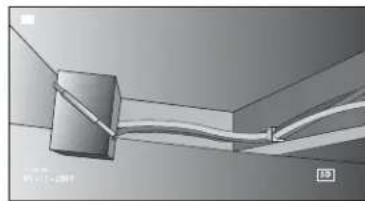
The inspection camera is designed to play real-time video while looking into walls and/or tight spaces. With a micro SD card (sold separately), the tool can then take photos or record videos for documentation purposes.
Photos are saved in JPG format and videos are saved as AVI. This DEWALT inspection camera is compatible with micro SD memory cards up to 16 gigabytes.
Applications consist of automotive inspection, plumbing inspection, HVAC inspection or cable routing. Read the entire manual before using this inspection camera.
DO NOT use in presence of flammable liquids or gases. The camera cable extension is waterproof up to the camera connector. DO NOT USE the handle set under wet conditions or submerge in liquid.
The inspection camera is a professional tool. DO NOT let children come into contact with the tool. Supervision is required when inexperienced operators use this tool.
- This product is not intended for use by persons (including children) suffering from diminished physical, sensory or mental abilities, or for lack of experience and/or for want of knowledge or skills unless they are supervised by a person responsible for their safety. Children should never be left alone to play with this product.
Electrical Safety
The charger has been designed for one voltage only. Always check that the battery pack voltage corresponds to the voltage on the rating plate. Also make sure that the voltage of your charger corresponds to that of your mains.

Your DEWALT charger is double insulated in accordance with EN 60335; therefore no earth wire is required.
If the supply cord is damaged, it must be replaced by a specially prepared cord available through the DEWALT service organisation.
Mains Plug Replacement (U.K. & Ireland Only)
If a new mains plug needs to be fitted:
• Safely dispose of the old plug.
- Connect the brown lead to the live terminal in the plug.
- Connect the blue lead to the neutral terminal.

WARNING: No connection is to be made to the earth terminal.
Follow the fitting instructions supplied with good quality plugs. Recommended fuse: 3 A.
Using an Extension Cable
An extension cord should not be used unless absolutely necessary. Use an approved extension cable suitable for the power input of your charger (see Technical data). The minimum conductor size is 1 mm ^2 ; the maximum length is 30 m.
When using a cable reel, always unwind the cable completely.
ASSEMBLY AND ADJUSTMENTS

WARNING: Prior to assembly and adjustment, always remove the battery pack. Always turn the inspection camera off before inserting or removing the battery pack.

WARNING: Use only DEWALT battery packs and chargers.
Screen (fi g. 4)
When the screen is attached to the handle set with a battery, it will receive a charge from the battery. Ensure the screen is fully charged before use.
When the screen is disengaged from the handle set, a battery icon appears in the upper left corner. This icon also displays the current charge of the screen.
To install the screen (e) into the handle set (g), align the screen with the rails on the handle set and slide it firmly into the handle until you hear the lock snap into place.
To remove the screen from the handle set, firmly slide the screen up from the tool handle.
The screen can be turned on and viewed when it is not attached to the handle set, allowing easier maneuverability of the camera.
Camera Cable (fi g. 5)
Align the camera cable (c) with the camera connector (d). Push in and turn the connector counterclockwise (camera screen facing you) to firmly attach.
To remove the camera cable, turn the connector clockwise (direction of arrow).
Additional camera cable and extensions are available at additional cost. Consult your dealer for further information.
Hook and Magnet (fi g. 6)
DCT410
The hook is beneficial for retrieving cable or wire located in tight spaces. The magnet is beneficial for retrieving metal objects in tight spaces.
To attach the hook or magnet, turn the knurled part of the camera counterclockwise until it stops.
Align the hook or magnet with the gray groove (t) then slide it down until the tabs (u) at the top of the hook/magnet are securely in the notches (v) located in the camera lens.
Turn the knurled part clockwise to lock the base of the hook and magnet.
Hook, Magnet and Mirror (fi g. 7, 8) DCT411
Follow the process below to assemble the hook, magnet or mirror onto the DCT411 9 mm camera.
- With the sleeve (w) on the accessory, insert the bottom of accessory (bent wire) into the hole (x) in the 9 mm camera cable.
- Make sure the accessory is in the groove (y) on the sleeve and slide the sleeve onto the camera until the sleeve covers the hole (x).

CAUTION: Cut Hazard. Use care when handling hook.
Belt Hook (fi g. 9) (Optional Accessory)

NG: To reduce the risk of serious personal injury, DO NOT suspend camera overhead or suspend objects from the belt hook. ONLY hang camera's belt hook from a work belt.

NG: To reduce the risk of serious personal injury, ensure the screw (z) holding the belt hook is secure.
IMPORTANT: When attaching or removing the belt hook, use only the screw (z) that is provided.
The belt hook (aa) can be attached to either side of the tool using only the screw (z) provided, to accommodate left- or right-handed users. If the hook is not desired at all, it can be removed from the tool.
To move belt hook, remove the screw (z) that holds the belt hook in place then reassemble on the opposite side.
OPERATION
Instructions for Use

VG: Always observe the safety instructions and applicable regulations.
Inserting and Removing the Battery Pack from the Inspection Camera (fi g. 10)
NOTE: Make sure your battery pack (a) is fully charged.
TO INSTALL THE BATTERY PACK INTO THE TOOL HANDLE
- Align the battery pack with the rails inside the handle.
- Slide it firmly into place until you hear the lock snap into place.
TO REMOVE THE BATTERY PACK FROM THE TOOL
-
Press the release button (bb) and firmly pull the battery pack out of the camera handle.
-
Insert battery pack into the charger as described in the charger section of this manual.
Getting Started
INITIAL SETUP
Language Setup
- Press the forward or back arrow to select English, German, Spanish, French, Italian or Dutch.

- Press the OK button to confirm and exit.
ENGLISH
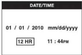
Date and Time Setup
- Press the forward or back arrow to highlight the field to change.

- Press the OK button to activate the field (field turns green).
- Press the forward or back arrow to change the activated field.
- Press the OK button to save changes (field turns yellow).
- Repeat above steps to change remaining fields.
- Press the main menu button to exit.
BASIC OPERATION
NOTE: At any time during the camera operation, pressing the main menu button will return to the previous menu.
To Record Photos or Videos (fig. 2, 3)
Be sure a micro SD card (sold separately) is loaded in the card slot (h).
- Turn both the camera (b) and the handle set (g) on.
- Aim camera at destination.
natural_image
3D diagram of a cable or wire connection between two vertical connectors (no text or symbols visible)A. Press the camera button (I) to take a photo.
A confirmation icon will appear in the top right side of screen.
OR
B. Press the record button (m) to start recording.
A red dot will appear in the top right side of the screen. To stop recording, press the record button again.
The camera will create a folder on the micro SD card for that day. All photos or videos taken that day will be stored in this folder.
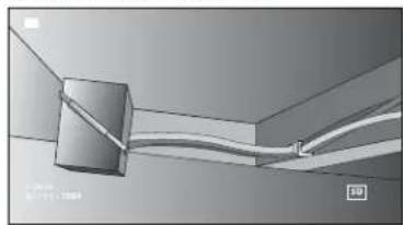
To View Photos or Videos
- Press the main menu button to show the Main Menu.
- Press the forward or back arrow to select the Folder option.
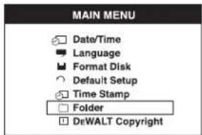
- Press the OK button to navigate to the next screen.
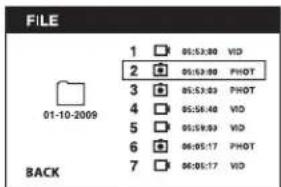
- Press the forward or back arrow to select a dated folder.
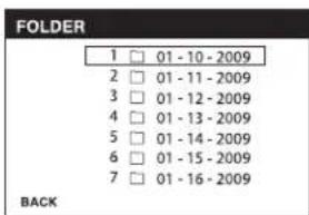
- Press the OK button to select the dated folder.
- Press the forward or back arrow to select the photo or video.
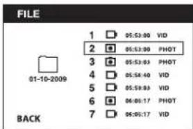
- Press the OK button to view the photo or video.
natural_image
3D rendering of a ceiling-mounted cable or tube with a central box, no visible text or symbols-
Press the forward or back arrow to advance to the next photo or video.
-
When finished, press the main menu button to exit.
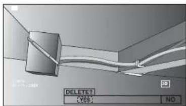
To Delete Individual Photos or Videos
- Press the main menu button to show the Main Menu.
- Press the forward or back arrow to select the Folder option.
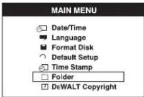
- Press the OK button to navigate to the next screen.
- Press the forward or back arrow to select a dated folder.

- Press the OK button to navigate to the next screen.
- Press the forward or back arrow to select a photo or video.
- Press the delete button. Select YES to delete the individual photo or video.
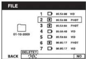
- Press the main menu button to exit.
To Delete a Photo or Video While Viewing
- Press the main menu button to show the Main Menu.
- Press the forward or back arrow to select the Folder option.
- Press the OK button to navigate to the next screen.
- Press the forward or back arrow to select a dated folder.

- Press the OK button to navigate to the next screen.
- Press the forward or back arrow to select a photo or video.
- Press the OK button to view.
natural_image
3D rendering of a ceiling-mounted cable or hose assembly with a cylindrical component (no text or symbols visible)- Press the delete button. Select YES to delete the individual photo or video.
ENGLISH
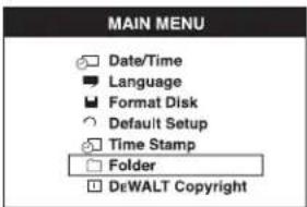
To Change Languages
- Press the main menu button to show the Main Menu.
- Press the forward or back arrow to select the Language option.
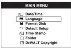
- Press the OK button to select.
- Press the forward or back arrow to select English, German, Spanish, French, Italian or Dutch.

- Press the OK button to save changes.
- Press the main menu button to exit.
To Change Date/Time
- Press the main menu button to show the Main Menu.
- Press the forward or back arrow to select Date/Time option.
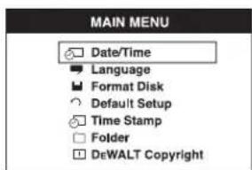
-
Press the OK button to navigate to the next screen.
-
Press the forward or back arrow to highlight a field to change.
- Press the OK button to activate the field (field turns green).
- Press the forward or back arrow to change the activated field.
- Press the OK button to save changes.
- Repeat above steps to change remaining fields.
- Press the main menu button to exit.
To Activate the Time Stamp
- Press the main menu button to show the Main Menu.
- Press the forward or back arrow to select the Time Stamp option.
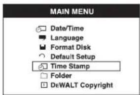
- Press the OK button to navigate to the next screen.
- Press the forward or back arrow to select OFF or ON.


- Press the OK button to save changes.
- Press the main menu button to exit.
To Format Micro SD Card
NOTICE: Formatting the micro SD card will erase all data.
- Press the main menu button to show the Main Menu.
- Press the forward or back arrow to select the Format Disk option.

- Press the OK button to navigate to the next screen.
- Press the forward or back arrow to select NO or YES.


- Press the OK button to save changes and exit.
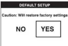
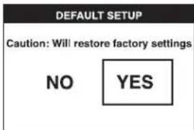
To Change Default Setup
NOTICE: Changing to default setup will erase current settings and restore factory settings.
-
Press the main menu button to show the Main Menu.
-
Press the forward or back arrow to select the Default Setup option.
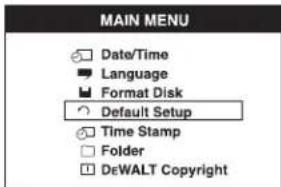
- Press the OK button to navigate to the next screen.
- Press the forward or back arrow to select NO or YES.
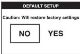
- Press the OK button to save changes and exit.
Operating Tips
• Use only DEWALT 10.8 V lithium ion battery.
- Ensure the DEWALT battery is in good working condition. If the low battery indicator light on the screen is flashing, the battery needs to be recharged.
- To extend battery life, make sure to turn both the screen and the handle set off when not in use.
- Make sure the screen is fully charged before operation.
MAINTENANCE
Your DEWALT inspection camera has been designed to operate over a long period of time with a minimum of maintenance. Continuous satisfactory operation depends upon proper tool care and regular cleaning.
ENGLISH
The charger and battery pack are not serviceable. There are no serviceable parts inside.

Cleaning

WARNING: Blow dirt and dust off with clean, dry air at least once a week. To minimize the risk of eye injury, always wear proper eye protection when performing this.

VG: Never use solvents or other harsh chemicals for cleaning the non-metallic parts of the tool. These chemicals may weaken the materials used in these parts. Use a cloth dampened only with water and mild soap. Never let any liquid get inside the tool; never immerse any part of the tool into a liquid.
CHARGER CLEANING INSTRUCTIONS

JG: Shock hazard. Disconnect the charger from the AC outlet before cleaning. Dirt and grease may be removed from the exterior of the charger using a cloth or soft non-metallic brush. Do not use water or any cleaning solutions.
Optional Accessories

WARNING: Since accessories, other than those offered by DEWALT, have not been tested with this product, use of such accessories with this tool could be hazardous. To reduce the risk of injury, only DEWALT recommended accessories should be used with this product.
RECOMMENDED ACCESSORIES
• DCT4101 – 17 mm diameter camera cable
• DCT4102 – 9 mm diameter camera cable
• DCT4105 – 5.8 mm diameter camera cable
- DCT4103 – 17 mm diameter, 0.9 m long cable extension
- Hook and magnet DCT410 (available only as spare parts)
- Hook, magnet and mirror DCT411 (available only as spare parts)
Consult your dealer for further information on the appropriate accessories.
Troubleshooting
• Make sure the 10.8 V battery is charged.
• Make sure the screen is fully charged.
- Make sure the screen is always attached to the handle set. The picture may freeze if you attempt to remove the screen from the handle set while taking a photo or video.
• Make sure the battery is installed on the handle set when in use.
• Make sure the camera cable is attached to the handle set properly.
• Make sure the handle set is turned on as well as the screen.
• Make sure the back of the handle set is not covered with debris so the screen slides on easily and no damage to the screen occurs.
- If the screen freezes or won't turn on, insert a small object (i.e., paper clip end) into the reset button (s) located on the back of the screen.
- If the picture is dim, roll the brightness control switch to brighten the LED light.
Protecting the Environment

Separate collection. This product must not be disposed of with normal household waste.

Should you find one day that your DEWALT product needs replacement, or if it is of no further use to you, do not dispose of it with household waste. Make this product available for separate collection.

Separate collection of used products and packaging allows materials to be recycled and used again. Re-use of recycled materials helps prevent environmental pollution and reduces the demand for raw materials.
Local regulations may provide for separate collection of electrical products from the household, at municipal waste sites or by the retailer when you purchase a new product.
DEWALT provides a facility for the collection and recycling of DEWALT products once they have reached the end of their working life. To take advantage of this service please return your product to any authorised repair agent who will collect them on our behalf.
You can check the location of your nearest authorised repair agent by contacting your local DEWALT office at the address indicated in this
manual. Alternatively, a list of authorised DEWALT repair agents and full details of our after-sales service and contacts are available on the Internet at: www.2helpU.com.

Rechargeable Battery Pack
This long life battery pack must be recharged when it fails to produce sufficient power on jobs which were easily done before. At the end of its technical life, discard it with due care for our environment:
- Run the battery pack down completely, then remove it from the tool.
- Li-lon cells are recyclable. Take them to your dealer or a local recycling station. The collected battery packs will be recycled or disposed of properly.
GUARANTEE
DEWALT is confident of the quality of its products and offers an outstanding guarantee for professional users of the product. This guarantee statement is in addition to and in no way prejudices your contractual rights as a professional user or your statutory rights as a private non-professional user. The guarantee is valid within the territories of the Member States of the European Union and the European Free Trade Area.
• 30 DAY NO RISK SATISFACTION GUARANTEE •
If you are not completely satisfied with the performance of your DEWALT tool, simply return it within 30 days, complete with all original components, as purchased, to the point of purchase, for a full refund or exchange. The product must have been subject to fair wear and tear and proof of purchase must be produced.
• ONE YEAR FREE SERVICE CONTRACT •
If you need maintenance or service for your DEWALT tool, in the 12 months following purchase, you are entitled to one service free of charge. It will be undertaken free of charge at an authorised DEWALT repair agent. Proof of purchase must be produced. Includes labour. Excludes accessories and spare parts unless failed under warranty.
• ONE YEAR FULL WARRANTY •
If your DEWALT product becomes defective due to faulty materials or workmanship within 12 months from the date of purchase, DEWALT guarantees to replace all defective parts free of charge or – at our discretion – replace the unit free of charge provided that:
• The product has not been misused;
- The product has been subject to fair wear and tear;
• Repairs have not been attempted by unauthorised persons;
• Proof of purchase is produced;
- The product is returned complete with all original components.
If you wish to make a claim, contact your seller or check the location of your nearest authorised DEWALT repair agent in the DEWALT catalogue or contact your DEWALT office at the address indicated in this manual. A list of authorised DEWALT repair agents and full details of our after-sales service is available on the Internet at: www.2helpU.com.
ESPAÑOL
natural_image
Pure electrical circuit lines without any symbolsnatural_image
3D rendering of a wall-mounted cable or pipe connection with a central box (no text or symbols visible)natural_image
3D rendering of a cylindrical pipe connected to a wall, with visible wiring and no text or symbolsnatural_image
3D architectural rendering of a wall-mounted cable or pipe system with a central component (no text or symbols visible)Cambiar Idiomas
Suspension de charge.

natural_image
3D rendering of a mechanical or electrical component with wires and connectors (no visible text or symbols)natural_image
3D rendering of a wall-mounted cable or wire connection with a central component (no text or symbols visible)natural_image
3D rendering of a ceiling-mounted cable or conduit with a central connector (no text or symbols visible)FRANÇAIS
Batterie rechargeable
Pulsante Zoom/Delete (Zoom/Elimina):
natural_image
3D rendering of a mechanical or electrical component with wires and a central block (no visible text or symbols)natural_image
3D rendering of a pipe connection with a cylindrical component and coiled tubing (no text or symbols visible)natural_image
3D rendering of a mechanical or electrical component with wires and a cylindrical housing (no visible text or symbols)WAARSCHUWING: Breng nooit

natural_image
3D diagram of a ceiling-mounted cable or wire installation with a central box and connecting wires (no text or symbols)natural_image
3D rendering of a cylindrical pipe connected to two cables in a corner (no text or symbols visible)natural_image
3D rendering of a ceiling-mounted cable or tube with a central connector (no text or symbols visible)natural_image
3D technical diagram showing a pipe connection with a cube and cable, no readable text or symbols presentAndere talen kiezen

WAARSCHUWING: Aangezien