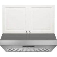
UTDRAG 903.923.29 - Basket IKEA - Free user manual and instructions
Find the device manual for free UTDRAG 903.923.29 IKEA in PDF.

| Product type | Telescopic hood |
| Brand | IKEA |
| Model | UTDRAG 903.923.29 |
| Width | 598.5 mm |
| Depth | 387 - 537 mm |
| Height min/max | 215 mm |
| Net weight | 7.6 kg |
| Total power | 108 W |
| Lighting | 2 x LED 4W, base E14 |
| Max air flow (extraction) | 340 m³/h |
| Max air flow (recirculation) | 140 m³/h |
| Max noise level (extraction) | 67 dBA |
| Max noise level (recirculation) | 72 dBA |
| Number of speeds | 3 |
| Grease filter | Dishwasher-safe, every 2 months |
| Charcoal filter | Regenerable (max 8 cycles), washable at 70°C |
| Minimum safety distance (gas) | 650 mm |
| Minimum safety distance (electric) | 500 mm |
| Exhaust duct diameter | 120 mm minimum |
| Energy efficiency class | B |
| Annual energy consumption | 38.6 kWh/year |
| Warranty | 5 years |
| Installation | Extraction or recirculation |
Frequently Asked Questions - UTDRAG 903.923.29 IKEA
User questions about UTDRAG 903.923.29 IKEA
0 question about this device. Answer the ones you know or ask your own.
Ask a new question about this device
Download the instructions for your Basket in PDF format for free! Find your manual UTDRAG 903.923.29 - IKEA and take your electronic device back in hand. On this page are published all the documents necessary for the use of your device. UTDRAG 903.923.29 by IKEA.
USER MANUAL UTDRAG 903.923.29 IKEA
Cleaning and maintenance 11
What to do if... 13
Technical data 14
Energy efficiency 15
Environmental aspects 15
IKEA guarantee 17
Safety information
For your own safety and correct operation of the appliance, please read this manual carefully before installation and operation. Always keep these instructions together with the appliance, even if it is sold or transferred to third parties. It is important that users are familiar with all the appliance's operating and safety characteristics.
△ Connection of the wiring must be performed by a specialist technician.
- The manufacturer cannot be held responsible for any damage resulting from incorrect or inadequate installation.
- The minimum safety distance between the cooker hob and the extractor hood is: for electrical hob 500mm and for gas hob 650mm.
- If the gas hob installation instructions specify a distance greater than that indicated above, this must be taken into account.
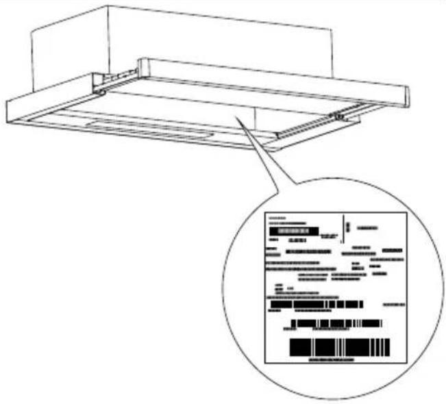
- Check that the mains voltage corresponds to that indicated on the rating plate fixed to the inside of the hood.
- The cut-out devices must be installed in the fixed system ac-
ENGLISH 7
cording to the wiring system regulations.
- For Class I appliances, check that the domestic power supply has a suitable earthing connection.
- Connect the hood to the flue with a pipe with a minimum diameter of 120 mm. The fume path must be as short as possible.
- All the regulations regarding air discharge must be complied with.
- Do not connect the extractor hood to exhaust ducts carrying combustion fumes (boilers, fireplaces, etc.).
- If the extractor is used in conjunction with non-electrical appliances (e.g. gas burning appliances), a sufficient degree of ventilation must be guaranteed in the room in order to prevent the backflow of exhaust gas. When the cooker hood is used in conjunction with appliances supplied with energy other than electricity, the negative pressure in the room must not exceed 4 Pa mbar to prevent fumes being drawn back into the room by the cooker hood.
- The air must not be discharged into a flue that is used for exhausting fumes from appliances burning gas or other fuels.
- The power cord, if damaged, must be replaced by the manufacturer or by a service technician.
- Connect the plug to a socket complying with current regulations, located in an accessible place.
- Regarding the technical and safety measures to be adopted for fume discharging it is important to strictly follow the regulations provided by the local authorities.
⚠ WARNING: Before installing the hood, remove the protective films.
- Use only screws and small parts of a type suitable for the hood.
⚠ WARNING: failure to install the screws or fixing devices in accordance with these instructions may result in electrical hazards.
- Connect the hood to the power supply by means of a bipolar switch with a distance between the contacts of at least 3 mm.
- Do not look directly at the light through optical devices (binoculars, magnifying glasses...).
- Do not flambé under the hood; risk of fire.
- This appliance can be used by children aged from 8 years and above and by persons with reduced physical, sensory or mental capabilities or lacking in experience and knowledge if they have been given supervision or instruction concerning use of the appliance in a safe way and if they understand the hazards involved. Children must not play with the appliance. Cleaning and maintenance by the user must not be performed by children, unless they are supervised.
- Children should be supervised to ensure that they do not play with the appliance.
- The appliance is not to be used by persons (including children) with reduced physical, sensory or mental capabilities, or lacking in experience and knowledge, unless they have been given supervision or instruction.
The accessible parts may become hot when used with cooking appliances.
- Clean and/or replace the filters after the time specified (fire hazard).
- There must be adequate ventilation of the room when the hood is used at the same time as appliances burning gas or other fuels (not applicable to appliances that only discharge the air back into the room).
- Kitchen hoods and other cooking fume extractors can affect
the safe operation of appliances which burn gas or other fuels (including those in other rooms) due to the backflow of combustion gases. These gases can cause carbon monoxide poisoning. After installing a kitchen extractor hood or any other cooking fume extractor, make sure that the gas appliances are tested by a certified technician to guarantee that there is no backflow of combustion gases.
- In case of replacement with halogen lamp use only self-shielded tungsten halogen lamps or self-shielded metal halide lamps."
General information
Use
- Switch off or unplug the appliance from the mains supply before carrying out any maintenance work.
- The top of the hood must not to be used as a shelf.
- The extractor hood has been designed exclusively to eliminate cooking smells in domestic use.
- Never use the extractor hood for purposes other than those for which it was designed.
- Never leave high flames under the extractor hood when it is on.
- Adjust the flame intensity to direct it onto the bottom of the pan only, making sure that it does not engulf the sides.
- Deep fat fryers must be continuously monitored during use: overheated oil can burst into flames.
Installation method
The hood has been designed for installation and use in the "suction version" or in the "air recirculation version".

Extraction version (see symbol in the allation instructions)
Cooking steam is suctioned and channelled outside the house through a discharge duct (not supplied), fitted to the hood steam outlet. Make sure that the outlet duct is properly installed at the air outlet, using a suitable connection system.

Air recirculation version (see symbol in installation instructions)
The air is filtered through one or more carbon filters, and then resent into the room.
Important: Ensure appropriate air circulation around the hood.
Important: If the hood is supplied without carbon filters and installed on recirculation mode, these must be fitted before the hood can be used. The filters are commercially available.
The hood should be installed away from particularly dirty areas, windows, doors and heat sources. Wall mounting accessories are not included as they vary depending on the wall material. Use fixing systems suitable for the walls of your home and for the weight of the appliance. For further details, contact a specialist dealer. Keep this booklet for future consultation.
Product description
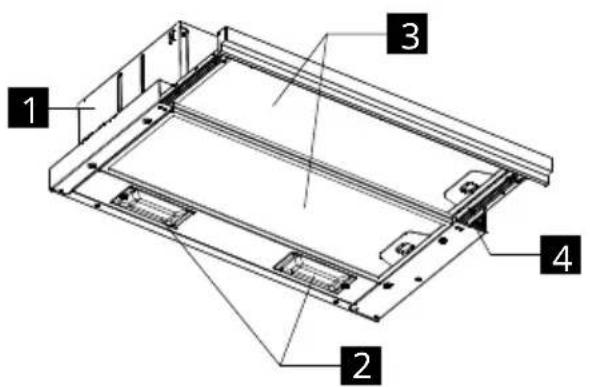
1 Hood body
2 Lighting
3 Grease filter
4 Control panel
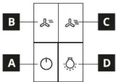
Control panel
flowchart
graph TD
    A["A"] --> B["B"]
    B --> C["C"]
    A --> D["D"]
    D --> C
    style A fill:#000,stroke:#000
    style B fill:#fff,stroke:#000
    style C fill:#fff,stroke:#000
    style D fill:#fff,stroke:#000
| A | Starts the motor at the first speed and turns off the motor at any speed. |
| B | Starts the motor at the second speed. |
| C | Starts the motor at the third speed. |
| D | Turns the lighting system on and off at maximum intensity. |
| * If the sliding intake panel is closed, the hood light and the motor are off. | |
General tips
- Operate the hood at minimum speed at the start of cooking and keep it running for a few minutes after cooking is finished.
- Only increase the speed in the presence of large quantities of smoke and steam and only use the booster speed(s) in extreme situations.
- Replace the filter or carbon filters when ne-
cessary to maintain good odour reduction efficiency.
- Clean the grease filter or filters when necessary to maintain good grease absorption efficiency.
- Use the maximum diameter of the ducting indicated in this manual to optimise efficiency and to minimise noise.
Cleaning and maintenance

Switch off or unplug the appliance from the mains supply before carrying out any maintenance work.
IMPORTANT: Clean the hood using a damp cloth and a neutral liquid detergent.
Long-life carbon filter
The odour filter can be washed and regenerated every 3-4 months (or more frequently if the hood is subject to intensive use), up to a maximum of 8 regeneration cycles (in case of particularly intensive use it is recommended that you do not exceed 5 cycles).
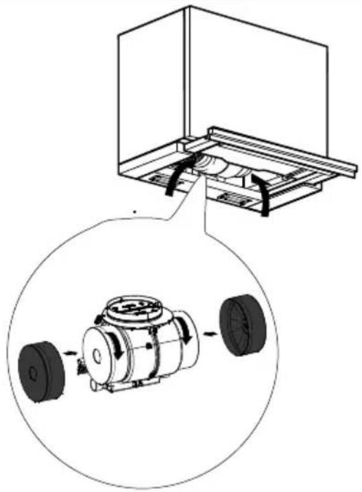
natural_image
Technical diagram showing a mechanical assembly with a housing and a close-up of a motor component (no text or labels)Regeneration procedure
- Wash in the dishwasher at a MAX temperature of 70^ or hand wash in hot water without using abrasive sponges (do not use detergents!).
- Dry in the oven at a MAX temperature of 70^ for 2 hours (it is advisable to carefully read the user manual and the assembly instructions of the oven you own).
ENGLISH 12
Grease filters
Clean or replace the filters continuously according to below time intervals, to maintain good performance of the hood and to prevent a potential fire hazard, caused by excessive grease build-up. The grease filters must be cleaned after every 2 months of operation or more frequently in the case of very intense use and are dishwasher safe.
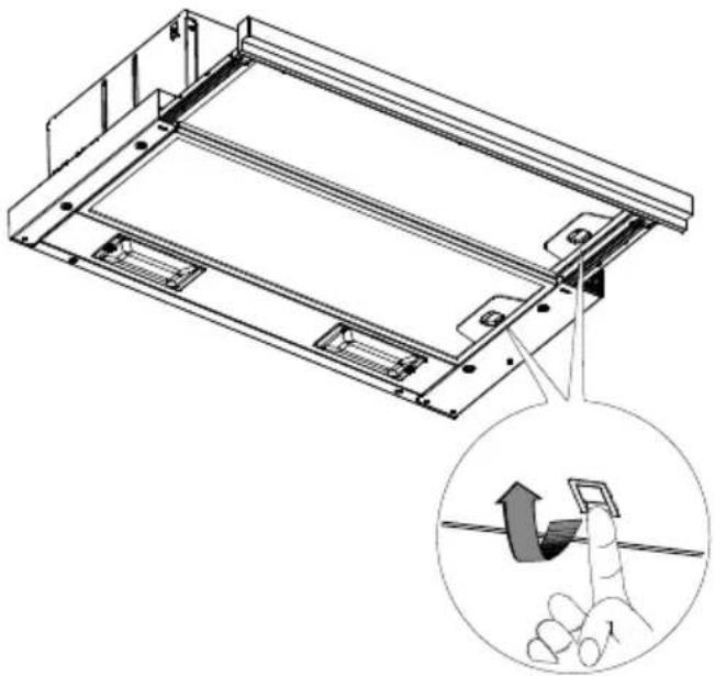
natural_image
Technical line drawing of a mechanical frame assembly with an inset showing a hand holding a small component (no text or symbols present)the same characteristics (4W power, E14 connection).
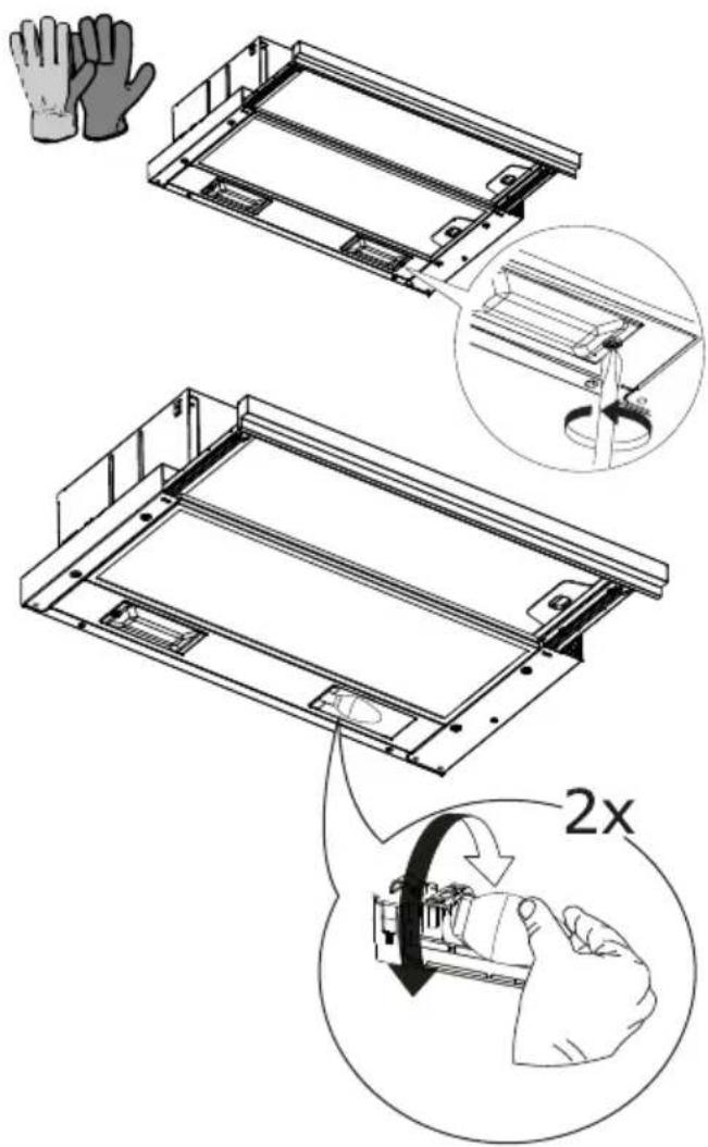
Light replacement
Unscrew the light bulbs using safety gloves and replace them with new light bulbs with
| Light Absorption (W) | Connec-tion | Voltage (V) | Dimensions (mm) | ILCOS code |
 | 4 E14 220-2 | 40 107x37 D | RBB/F-4-220-240-E14-35/100 |
What to do if...
If there is a fault, first try to find a solution yourself. If you are unable to resolve the problem yourself, contact an authorised service centre.
In the event of improper use of the appliance or installation carried out without respecting the assembly instructions, it may be necessary to pay for the visit of an Authorised Service Centre technician, even during the warranty period.
| PROBLEM POSSIBLE CAUSE SOLUTION | ||
| The device is not stable. | The appliance has not been installed correctly. | Follow the installation instructions supplied with the appliance. |
| The appliance is not level. | The appliance has not been installed correctly. | Follow the installation instructions supplied with the appliance. |
| The performance in terms of grease capture is not satisfactory. | Presence of oil and grease on the metal filters or on the carbon filters. | Observe the cleaning frequency of the filters as described in the user manual. |
| The appliance does not work. | The device has not been connected correctly. | Check that the mains cable is connected to the motor unit or that the plug is connected to the socket. |
| The light doesn't work. The LED is broken. For replacement, contact an Authorised Service Centre. | ||
| The hood is noisier than the customer's expectations. | The diameter of the air vent in the wall is too small and causes the pressure to drop and the motor speed to increase. | Follow the installation instructions supplied with the appliance. |
| The product is installed in recirculation mode. | The product in recirculation mode (and with the carbon filter fitted) is noisier than a product in suction mode. | |
| The ventilation duct has more than one bend. | If the fume evacuation system of the building has multiple bends or covers a long distance, the product may be noisier. | |
| Button A flashes once per second. | Grease filters alarm. | Clean the grease filter and reset the alarm. Consult the care and maintenance guide and the control panel guide to reset the filter alarm. |
| Button A flashes twice per second. | Activated carbon filters alarm. | Clean the activated carbon filter and reset the alarm. Consult the care and maintenance guide and the control panel guide to reset the filter alarm. |
Before contacting the Authorised Service Centre:
Turn the power back on to check whether the problem has disappeared. If this is not the case, turn it off and repeat the operation after one hour. If the appliance still does not work correctly after carrying out the checks listed
in the troubleshooting guide and turning the appliance back on, contact the Authorised Service Centre clearly explaining the problem and specifying:
- the type of fault;
- the model;
- the type and serial number of the appliance (indicated on the data plate).
Technical data
| Unit Value | ||
| Type of product | ||
| Dimensions | Width | mm 598.5 |
| Depth | mm Min. | |
| Min./max. height | mm 215 | |
| Max air flow* - Output | m3/h 340 | |
| Noise max* - Exhaust | dBA 67 | |
| Airflow max* - Recirculating | m3/h 140 | |
| Noise max* - Recirculating | dBA 72 | |
| Total power | W 108 | |
| Information on the light | Type | |
| Number and power | ||
| Connection | ||
| Minimum installation height - gas hob | mm 650 | |
| Minimum installation height - electric hob | mm 500 | |
| Net weight | Kg 7.6 | |
| * Maximum speed (without booster setting) | ||
This appliance has been designed, manufactured and sold in compliance with the EEC directives CE
This appliance has been designed, manufactured and marketed in compliance with the directives UK CA
The technical data are shown on the plate applied inside the appliance.
Energy efficiency
| Product fiche information, according to 65/2014 | Unit Value | |
| Supplier's name | IKEA | |
| Model id | UTDRAG103.891.42603.922.98903.923.29 | |
| Annual energy consumption | kWh/a 38.6 | |
| Energy Efficiency Class | B | |
| Fluid dynamics efficiency | 18.1 | |
| Fluid Dynamic Efficiency Class | C | |
| Lighting Efficiency | lux/Watt 16 | |
| Lighting Efficiency Class | D | |
| Grease Filtering Efficiency | % 85.1 | |
| Grease Filtering Efficiency Class | B | |
| Air flow at minimum speed | m3/h 170 | |
| Air flow at maximum speed | m3/h 340 | |
| Air flow at booster speed | m3/h N/A | |
| Air-weighted sound power emission at minimum speed | dbA 54 | |
| Air-weighted sound power emission a maximum speed | dbA 67 | |
| Air-weighted sound power emission at booster speed | dbA N/A | |
| Power Consumption in off mode | Watt 0.0 | |
| Power Consumption in standby mode | Watt N/A | |
| Additional information according to 66/2014 | ||
| Time increase factor | 13 | |
| Energy efficiency index | 66.9 | |
| Air flow measured at the optimum efficiency point | m3/h 194.0 | |
| Air pressure measured at the optimum efficiency point | Pa 232 | |
| Maximum air flow | m3/h 340.0 | |
| Electrical power supply measured at the optimum efficiency point | W 69.0 | |
| Nominal power of the lighting system | W 8.0 | |
| Average illumination of the lighting system on the cooking surface | lux 130 | |
| Sound power level at the highest setting | dBA 67 | |
Environmental aspects
Information on disposal Your obligations as an end-user

This electrical or electronic equipment is linked with a crossed-out wheeled bin. The equipment may therefore only be collected returned separately from unsorted municipal waste, i.e. it must not be disposed with household waste. The equipment can be returned, for example, to a municipal election point or, if applicable, to a tributor (see below for their take-back gations in Germany). This also applies to components, subassemblies and sumables of the old equipment to be disposed of.
Before the old equipment may be disposed of all old batteries and old accumulators that are not enclosed by the old equipment must be separated from the old equipment. The same applies to lamps that can be removed from the old equipment without destroying them. The end-user is also responsible for deleting personal data from the old equipment.
Notes on recycling

Help recycle all materials marked with this symbol. Do not dispose of such materials, especially packaging, in the household waste t via the relevant containers provided or e appropriate local collection systems.
Help to protect the environment and human health by recycling including waste of electrical and electronic appliances.
The following additional information applies in Germany.
Take-back obligations of distributors
Anyone who sells electrical and electronic equipment on a sales floor area of at least 400 m^2 or otherwise supplies it to end users on a commercial basis is obliged, when supplying a new equipment, to take back at the place of supply or in the immediate vicinity thereof free of charge an old
equipment belonging to the end user of the same type of equipment which fulfils essentially the same functions as the new equipment. This also applies to distributors of groceries with a total sales area of at least 800 m ^2 who offer electrical and electronic equipment several times a calendar year or on a permanent basis and make it available on the market. In addition, such distributors must, at the request of the end-user, take back in the retail shop or in the immediate vicinity free of charge old equipment that does not exceed 25 cm in any external dimension (small electrical equipment) thereof; in this case, take-back may not be linked to the purchase of an electrical or electronic equipment but may be limited to three old equipment per type of equipment.
The place of delivery is also the private household if the new electrical or electronic equipment is delivered; in this case the collection of the old equipment is free of charge for the end user.
The above obligations also apply to distribution using means of distance communication if the distributors maintain storage and dispatch areas for electrical and electronic equipment or total storage and dispatch areas for groceries that correspond to the sales areas mentioned above. However, the free collection of electrical and electronic equipment is then restricted to heat transmitters (e.g. refrigerators), screens, monitors and equipment containing screens with a surface area of more than 100 cm^2 and equipment where at least one of the external dimensions is more than 50 cm. For all other electrical and electronic equipment the distributor must ensure appropriate return facilities within a reasonable distance from the respective end-user; this also applies to small electrical equipment (see above) that the end-user wishes to return without purchasing a new equipment.
IKEA guarantee
How long is the IKEA warranty valid for?
This warranty is valid for five (5) years from the original purchase date of the appliance from IKEA. The original receipt is essential as a proof of purchase. Any repairs carried out under warranty do not extend the warranty period for the appliance.
Who provides support?
Customer support will be provided by the service provider appointed by IKEA through its organisation or network of authorised service partners.
What does the warranty cover?
The warranty covers any defects linked to the materials or manufacture of the household appliance and is valid from the purchase date of the household appliance at an IKEA store. The warranty is only valid on household appliances intended for household use. The exceptions are outlined under “What doesn’t the warranty cover”. In the period covered by the warranty, the repair costs (spare parts, labour and travel costs of the technical personnel) will be borne by the support service, provided that access to the appliance to perform the repair work does not entail unforeseen expenses. These conditions comply with the EU directive (No. 99/44/EC) and the applicable local legal provisions. The parts replaced will become the property of IKEA.
How will IKEA intervene to solve the problem?
The service provider, appointed by IKEA, will examine the product and decide, at its sole discretion, whether it is covered by the warranty. If so, the IKEA service provider or its authorised service partner, through its service centres, will, at its sole discretion, either repair the defective product or replace it with a product of the same or equal value.
What doesn't the warranty cover?
- Normal wear.
- Deliberate damage or due to negligence, damage caused by failure to follow the operating instructions, improper installation or connection to the incorrect voltage, damage caused by chemical or electrochemical reactions, rust, corrosion or water damage, including but not limited to damage caused by excessive limescale in the water pipes, and damage caused by weather and natural events.
- Parts subject to wear, e.g. batteries and light bulbs.
- Decorative and non-functional parts which do not affect normal use of the appliance, including scratches and changes in colour.
- Accidental damage caused by substances or foreign bodies and cleaning or releasing filters, drainage systems or detergent drawers.
- Damage to parts such as ceramic hobs, accessories, crockery and cutlery baskets, inlet and outlet pipes, gaskets, bulbs and their covers, screens, knobs, covers and parts of covers, unless it can be demonstrated that said damage was caused by manufacturing defects.
- Cases in which no defects are found during the technician call-out.
- Repairs not carried out by the IKEA-appointed service provider or by an authorised service partner, or repairs where non-original parts have been used.
- Repairs caused by improper installation or installation that does not comply with the specifications.
- Use of the household appliance in non-household settings, e.g. for professional use.
- Damage due to transportation. If the customer transports the appliance to his/her home or to another address, IKEA cannot be held responsible for any damage which occurs during transportation. However, if transportation to the customer's address is carried out by IKEA, any damage due to transportation will be covered by this warranty.
ENGLISH 18
- Cost of initial installation of the IKEA appliance. If an IKEA-appointed service provider or its authorised service partner repairs or replaces the equipment under the warranty, in any case the supplier or authorised service partner must also reinstall the repaired appliance or the replacement appliance, where necessary.
These limitations do not apply to work carried out properly by qualified personnel and using original parts to adapt the appliance to the safety standards of another EU country.
Applicability of national laws
The IKEA warranty gives the customer specific legal rights in addition to the statutory rights that vary from country to country. These conditions do not, however, in any way limit the consumer's rights outlined in the local legislation.
Area of validity
For household appliances purchased in an EU country and transferred to another EU country, the services will be provided under the warranty conditions which apply in the new country. The obligation to provide the service under the terms of the warranty only exists if the appliance is compliant and installed in accordance with the:
- technical specifications of the country in which the application of the warranty is requested;
- safety information outlined in the user manual.
After-sales service for IKEA appliances:
Do not hesitate to contact the IKEA after-sales service to:
-
request support under the warranty;
-
ask for clarification on the installation of IKEA appliances in specific IKEA kitchen cabinets. The service will not provide support or clarifications about:
- the installation of complete IKEA kitchens;
• electrical connections (if the appliance is supplied without cables and plugs), hydraulic connections and connections to the
gas supply that must be carried out by an authorised service technician.
- ask for clarification on the contents of the user manual and specifications of the IKEA appliance.
To ensure the best possible assistance, please read the assembly instructions and/or user manual carefully before contacting us.
How to contact us if you need our intervention

Consult the complete list of IKEA service providers and relevant local phone numbers on the last page of this manual.
Important! To ensure faster service, we recommend that you use the telephone numbers listed at the end of this manual. To request support, always refer to the specific appliance codes indicated in this manual. Before contacting us, make sure you know the IKEA product code (8 digits) of the appliance for which you are requesting support.
Important! KEEP THE RECEIPT!
It is your proof of purchase and it must be produced to allow you to make use of the warranty. The receipt also indicates the name and code (8-digit) of each IKEA appliance you have purchased.
Do you need any more help?
For any other questions not related to the after-sales service on the appliance, please contact the nearest IKEA store. Please read the documentation about the appliance carefully before contacting us.
Inhalt
natural_image
Technical diagram of a mechanical assembly with a zoomed-in view showing internal components (no text or labels)natural_image
Technical line drawing of a structural frame with an inset showing hand positioning and force application (no text or symbols)natural_image
Technical line drawing of a mechanical assembly with an inset magnified detail showing internal components (no text or symbols)Energie-Effizienz
natural_image
Technical diagram of a mechanical assembly with a zoomed-in view showing internal components (no text or labels)natural_image
Technical line drawing of a structural frame with an inset showing hand positioning and force application (no text or symbols)| Lam pe | Absorption (W) | At-tache | Vol-tage (V) | Dimen-sions (mm) | Code ILCOS |
| 4 E14 | 220-240 | 107x37 | DRBB/F-4-220-240-E14-35/100 |
Que faire si...
natural_image
Technical line drawing of a mechanical assembly with an inset showing internal components (no text or symbols)natural_image
Technical diagram showing a mechanical assembly with a zoomed-in view of a component (no text or labels present)natural_image
Technical line drawing of a mechanical assembly with an inset showing a hand pressing a component (no text or symbols present)
natural_image
Technical line drawing of a mechanical assembly with an inset showing internal components (no text or symbols)natural_image
Technical diagram showing a mechanical assembly with a zoomed-in view of a motor component (no text or labels present)natural_image
Technical line drawing of a mechanical frame assembly with an inset showing a hand holding a small device (no text or symbols present)| Lampe | Forbrug (W) | Kob-ling | Spæn-ding (V) | Dimen-sion (mm) | ILCOS-kode |
| 4 E14 | 220-240 | 107x37 | DRBB/F-4-220-240-E14-35/100 |
Energieffektivitet
natural_image
Technical diagram of a mechanical assembly with a zoomed-in view showing internal components (no text or labels)Regenereringsprosedyre
natural_image
Technical line drawing of a mechanical assembly with an inset showing a hand holding a small component (no text or symbols present)
natural_image
Technical line drawing of a mechanical assembly with an inset showing internal components (no text or symbols)Energieffektivitet
| Informasjon på produktmerking i henhold til 65/2014 | Enhet Verdi | |
| Leverandørnavn | IKEA | |
| Modellbetegnelse | UTDRAG103.891.42603.922.98903.923.29 | |
| Effektivt årlig konsum | kWh/a 38,6 | |
| Energieffektivitetsklasse | B | |
| Fluiddynamisk effektivitet | 18,1 | |
| Fluiddynamisk effektivitetsklasse | C | |
| Lyseffektivitet | lux/Watt 16 | |
| Lyseffektivitetsklasse | D | |
| Fettfiltreringseffektivitet | % 85,1 | |
| Fettfiltreringseffektivitetsklasse | B | |
| Luftstrømning ved minste hastighet | m^3/t 170 | |
| Luftstrømning ved største hastighet | m^3/t 340 | |
| Luftstrømning ved intensiv hastighet | m^3/t N/A | |
| A-vektet lydeffektemisjon i luften ved minste hastighet | dbA 54 | |
| A-vektet lydeffektemisjon i luften ved største hastighet | dbA 67 | |
| A-vektet lydeffektemisjon i luften ved intensiv hastighet | dbA N/A | |
| Strømforbruk i av-modus | Watt 0,0 | |
| Strømforbruk i standby-modus | Watt N/A | |
| Ekstra informasjon i henhold til 66/2014 | ||
| Tidsøkefaktor | 13 | |
| Energieffektivitetsindeks | 66,9 | |
| Målt luftstrømningsmengde ved punktet for beste virkningsgrad | m^3/t 194,0 | |
| Målt lufttrykk ved punktet for beste virkningsgrad | Pa 232 | |
| Maks luftstrømning | m^3/t 340,0 | |
| Målt elektrisk inngangseffekt ved punktet for beste virkningsgrad | W 69,0 | |
| Nominell effekt i lysanlegg | W 8,0 | |
| Middels lysanleggsbelysning på platetopp | lux 130 | |
| Lydeffektnivå ved maksimal innstilling | dBA 67 | |
Miljøaspekter
natural_image
Technical diagram showing a mechanical assembly with a housing and a close-up of a motor component (no text or labels)Regenerointimenettely
natural_image
Technical line drawing of a mechanical assembly with an inset showing a hand pressing a component (no text or symbols present)
Lamppujen vaihto
natural_image
Technical line drawing of a mechanical assembly with an inset showing internal components (no text or symbols)Energiatehokkuus
natural_image
Technical diagram of a mechanical assembly with a zoomed-in view showing internal components (no text or labels)natural_image
Technical line drawing of a mechanical frame assembly with an inset showing a hand holding a small component (no text or symbols present)
Utbyte av lampor
natural_image
Technical line drawing of a mechanical assembly with an inset showing internal components (no text or symbols)Energieffektivitet
natural_image
Technical diagram of a mechanical assembly with a zoomed-in view showing internal components (no text or labels)Endurnýtingarferli
natural_image
Technical line drawing of a mechanical frame assembly with an inset showing a hand holding a small component (no text or symbols present)Skipti á ljósum
| Ljós Sog | (W) Tenging Spenna | (V) Mál (m) | m) ILCOS-kóði | ||
 | 4 E14 220-2 | 40 107x37 D | RBB/F-4-220- | 240-E14-35/100 |
natural_image
Technical line drawing of a mechanical assembly with an inset magnified detail showing internal components (no text or symbols)Orkunýtni
natural_image
Technical diagram showing a mechanical assembly with a zoomed-in view of a component (no text or labels present)natural_image
Technical line drawing of a mechanical assembly with an inset showing a hand pressing a button on a horizontal line (no text or symbols present)
natural_image
Technical diagram of a mechanical assembly with a zoomed-in view showing internal components (no text or labels)natural_image
Technical line drawing of a mechanical assembly with an inset showing a hand pressing a component (no text or symbols present)
natural_image
Technical diagram of a mechanical assembly with a zoomed-in view showing internal components (no text or labels)natural_image
Technical line drawing of a mechanical frame assembly with an inset showing a hand interacting with a device (no text or symbols present)natural_image
Technical line drawing of a mechanical assembly with an inset magnified detail showing internal components (no text or symbols)Ενεργειακή Απόδοση
natural_image
Technical diagram showing a mechanical assembly with a housing and a close-up of a motor component (no text or labels)natural_image
Technical line drawing of a mechanical assembly with an inset showing a hand pressing a component (no text or symbols present)
Vervanging lampen
natural_image
Technical line drawing of a mechanical assembly with an inset magnified detail showing internal components (no text or symbols)Energie-efficiëntie
natural_image
Technical diagram of a mechanical assembly with a zoomed-in view showing internal components (no text or labels)natural_image
Technical line drawing of a mechanical frame assembly with an inset showing a hand holding a small component (no text or symbols present)
Wymiana żarówek
natural_image
Technical diagram showing a mechanical assembly with a housing and a close-up of a motor component (no text or symbols present)Yenileme prosedürü
natural_image
Technical line drawing of a mechanical assembly with an inset showing a hand pressing a component (no text or symbols present)
natural_image
Technical line drawing of a mechanical assembly with an inset magnified detail showing internal components (no text or symbols)Enerji Verimi
natural_image
Technical diagram showing a mechanical assembly with a housing and a close-up of a motor component (no text or symbols present)Postup regenerácie
natural_image
Technical line drawing of a mechanical assembly with an inset showing a hand pressing a component (no text or symbols present)
Výmena žiaroviek
natural_image
Technical line drawing of a mechanical assembly with an inset magnified detail showing internal components (no text or symbols)natural_image
Technical diagram showing a mechanical assembly with a housing and a close-up of a motor component (no text or labels)Postupak regeneriranja
- Operite u perilici posuđa na MAX temperaturi od 70° ili ručno operite vrućom vodom bez upotrebe abrazivnih spužvi (nemojte koristiti deterdžente!).
- Osušite u pećnici na MAX temperaturi od 70° tijekom 2 sata (preporučujemo da pažljivo pročitate korisnički priručnik i upute za montažu pećnice).
HRVATSKI 233
Filtar za masnoću
natural_image
Technical line drawing of a mechanical assembly with an inset showing a hand holding a small component (no text or symbols present)Zamjena lampica
Odvijte žarulje u zaštitnim rukavicama i zamijenite ih novim žaruljama istih karakteristika (snaga 4W, grlo E14).

| Ža-rulja | Potroš-nja (W) | Pri-klju-čak | Na-pon (V) | Dimen-zije (mm) | ILCOS kod |
| 4 E14 | 220-240 | 107x37 | DRBB/F-4-220-240-E14-35/100 |
Što učiniti ako...
natural_image
Technical line drawing of a mechanical assembly with an inset magnified detail showing internal components (no text or symbols)Energetska učinkovitost
natural_image
Technical diagram showing a mechanical assembly with a housing and a close-up of a motor component (no text or labels)Postopek regeneracije
natural_image
Technical line drawing of a mechanical frame assembly with an inset showing a hand holding a small component (no text or symbols present)Zamenjava luči
| Sve-tilka | Absorp-cija (W) | Prik lop | Na-pe-tost (V) | Mere (mm) | Koda ILCOS |
| 4 E14 | 220-240 | 107x37 | DRBB/F-4-220-240-E14-35/100 |
Kaj narediti, če...
Energetska učinkovitost
natural_image
Technical diagram showing a mechanical assembly with a zoomed-in view of a component (no text or symbols present)natural_image
Technical line drawing of a mechanical frame assembly with an inset showing a hand holding a small component (no text or symbols present)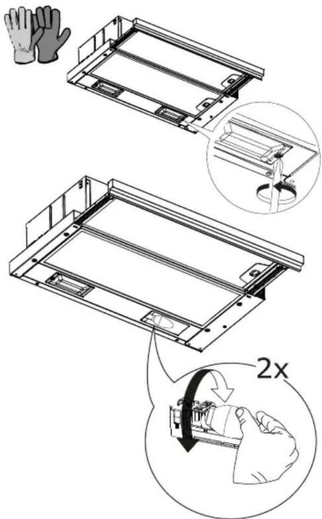
Замена сијалица
natural_image
Technical line drawing of a mechanical assembly with an inset showing internal components (no text or symbols)natural_image
Technical diagram showing a mechanical assembly with a housing and a close-up of a motor component (no text or symbols present)Postup regenerace
natural_image
Technical line drawing of a mechanical assembly with an inset showing a hand holding a small component (no text or symbols present)
Výměna žárovek
natural_image
Technical diagram showing a mechanical assembly with a zoomed-in view of a component (no text or labels present)Regeneráló eljárás
natural_image
Technical line drawing of a mechanical assembly with an inset showing a hand holding a small component (no text or symbols present)
Lámpák cseréje
natural_image
Technical line drawing of a mechanical assembly with an inset magnified detail showing internal components (no text or symbols)Energiahatékonyság
natural_image
Technical diagram showing a mechanical assembly with a zoomed-in view of a motor component (no text or labels present)natural_image
Technical line drawing of a mechanical frame assembly with an inset showing a hand interacting with a device (no text or symbols present)Заменете лампите
| Лам-па | Консу-мация(W) | Свърз-ва-не | Напре-же-ние(V) | Раз-мер(mm) | Код ILCOS |
| 4 E14 | 220-240 | 107x37 | DRBB/F-4-220-240-E14-35/100 |
natural_image
Technical diagram showing a mechanical assembly with a housing and a close-up of a motor component (no text or labels)natural_image
Technical line drawing of a mechanical assembly with an inset showing a hand pressing a component (no text or symbols present)
Important! PĂSTRAȚI BONUL FISCAL!
natural_image
Technical diagram of a mechanical assembly with a zoomed-in view showing internal components (no text or labels)natural_image
Technical line drawing of a mechanical assembly with an inset showing a hand holding a small component (no text or symbols present)
Lampu nomaina
natural_image
Technical line drawing of a mechanical assembly with an inset showing internal components (no text or symbols)Energoefektivitäte
natural_image
Technical diagram showing a mechanical assembly with a zoomed-in view of a component (no text or symbols present)natural_image
Technical line drawing of a mechanical assembly with an inset showing a hand holding a small component (no text or symbols present)
Lempučių keitimas
natural_image
Technical line drawing of a mechanical assembly with an inset showing internal components (no text or symbols)natural_image
Technical diagram showing a mechanical assembly with a housing and a close-up of a motor component (no text or symbols present)natural_image
Technical line drawing of a mechanical assembly with an inset showing a hand pressing a component (no text or symbols present)
Lambi vahetus
Energiatõhusus
natural_image
Technical diagram of a mechanical assembly with a zoomed-in view showing internal components (no text or labels)natural_image
Technical line drawing of a mechanical assembly with an inset showing a hand holding a small device (no text or symbols present)استبideal المصابيح