CMP21PL - Coffee machine BLACK & DECKER - Free user manual and instructions
Find the device manual for free CMP21PL BLACK & DECKER in PDF.

| Product Type | Pneumatic Framing Nailer |
| Brand | Black & Decker |
| Model | CMP21PL |
| Recommended Operating Pressure | 5–8.5 kg/cm² (70–120 p.s.i.g.) |
| Air Consumption | 277 L/min at 7 kg/cm² (9.75 CFM at 100 p.s.i.g.) |
| Magazine Capacity | 60 nails |
| Compatible Nail Type | Round head framing nails, plastic collation, 20°–22° angle |
| Nail Lengths | 113 mm – 148 mm (2 in – 3½ in) |
| Nail Diameters | 2.87 mm – 3.76 mm (0.113 in – 0.148 in) |
| Air Inlet | 1/4 in NPT |
| Trigger Modes | Single sequential and contact (bump) with selector |
| Depth Adjustment | Rotary dial with detents |
| Directional Exhaust Deflector | Yes, 8 positions |
| Removable No-Mar Pad | Yes, for angled nailing |
| Lubrication Required | Non-detergent SAE 20 pneumatic tool oil |
| Safety | Trigger lock, contact trigger, mandatory eye and ear protection |
| Warranty | 3-year limited, 90-day satisfaction guaranteed |
Frequently Asked Questions - CMP21PL BLACK & DECKER
User questions about CMP21PL BLACK & DECKER
0 question about this device. Answer the ones you know or ask your own.
Ask a new question about this device
Download the instructions for your Coffee machine in PDF format for free! Find your manual CMP21PL - BLACK & DECKER and take your electronic device back in hand. On this page are published all the documents necessary for the use of your device. CMP21PL by BLACK & DECKER.
USER MANUAL CMP21PL BLACK & DECKER
INSTRUCTION MANUAL | GUIDE D'UTILISATION | MANUAL DE INSTRUCTIONS
IF YOU HAVE QUESTIONS OR COMMENTS, CONTACT US.
POUR TOUTE QUESTION OU TOUT COMMENTAIRE, NOUS CONTACTER.
SI TIENE DUDAS O COMENTARIOS, CONTÁCTENOS.
1-888-331-4569 WWW.CRAFTSMAN.COM
English (original instructions) 1
Definitions: Safety Alert Symbols and Words
This instruction manual uses the following safety alert symbols and words to alert you to hazardous situations and your risk of personal injury or property damage.
DANGER: Indicates an imminently hazardous situation which, if not avoided, will result in death or serious injury.
WARNING: Indicates a potentially hazardous situation which, if not avoided, could result in death or serious injury.
CAUTION: Indicates a potentially hazardous situation which, if not avoided, may result in minor or moderate injury.
(Used without word) Indicates a safety related message.
NOTICE: Indicates a practice not related to personal injury which, if not avoided, may result in property damage.
Fig. A
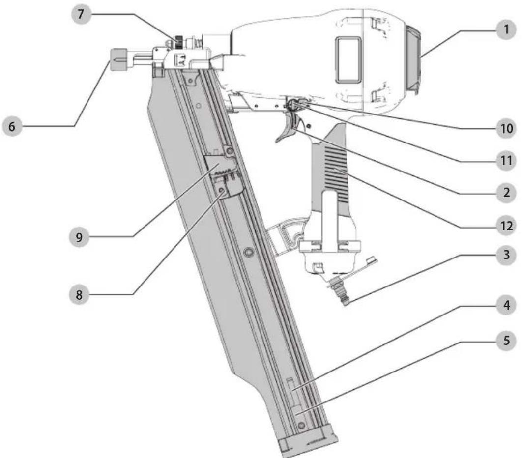
COMPONENTS
1 Exhaust deflector
2 Trigger
3 1/4" fitting
4 Magazine
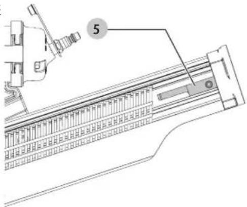
5 Nail stop
6 Contact trip with no-mar pad
7 Depth adjustment wheel
8 Pusher release
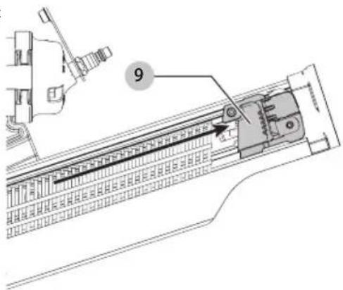
9 Pusher
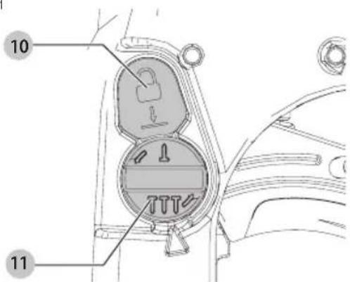
10 Trigger lock button
11 Mode selector button
12 Handle
WARNING: Read all safety warnings and all
instructions. Failure to follow the warnings and instructions may result in electric shock, fire and/or serious injury.
WARNING: Never modify the product or any part of it. Damage or personal injury could result.

WARNING: To reduce the risk of injury, read the instruction manual.
If you have any questions or comments about this or any product, call CRAFTSMAN toll free at: 1-888-331-4569.
21° Round Head Framing Nailer CMP21PL
IMPORTANT SAFETY INSTRUCTIONS
WARNING: Only persons who have read and understand the tool operating/safety instructions should operate the tool.
WARNING: Actuating tool may result in flying collation material, or dust which could harm operator's eyes. Operator and others in work area MUST wear safety glasses with side shields. These safety glasses must conform to ANSI Z87.1 requirements (approved glasses have "Z87" printed or stamped on them). Employer is responsible for enforcing the usage of eye protection equipment by the tool operator and all other personnel in the work area.
WARNING: Always assume that the tool contains fasteners.
WARNING: (Air and Supply)
Do not use oxygen, combustible gases, or bottled gases as a power source for this tool as tool may explode, possibly causing injury.
- Do not use supply sources which can potentially exceed 200 p.s.i.g. (14 kg/cm ^2 ) as tool may burst, possibly causing injury.
- The connector on the tool must not hold pressure when air supply is disconnected. If a wrong fitting is used, the tool can remain charged with air after disconnecting and thus will be able to drive a fastener even after the air line is disconnected possibly causing injury.
- Do not pull the trigger while connected to the air supply as the tool may cycle, possibly causing injury.
• Always disconnect air supply: 1.) Before making adjustments; 2.) When servicing the tool; 3.) When clearing a jam; 4.) When tool is not in use; 5.) When moving to a different work area, as accidental actuation may occur, possibly causing injury.
WARNING: When loading tool:
Never place a hand or any part of body in fastener discharge area of tool.
- Never point tool at yourself or anyone else.
- Do not pull the trigger as accidental actuation may occur, possibly causing injury.
- Be careful when handling fasteners, especially when loading and unloading, as the fasteners have sharp points.
WARNING: Do not operate tool if:
There is any damage to air hose or fitting.
• The tool leaks air.
- The tool has received a sharp blow, malfunctions or is dropped or damaged in any manner. Return tool to the nearest authorized service facility for examination, repair, or mechanical adjustment.
- Warning labels are missing or damaged.
- Tool is not in proper working order. Tags and physical segregation shall be used for control.
- Tool is without workpiece contact. A tool without workpiece contact can be fired unintentionally causing injury to an operator or a bystander.
WARNING: When operating the tool:
Always handle the tool with care:
- Never engage in horseplay.
- Never pull the trigger unless nose is directed toward the work.
- Never point the tool at yourself or others.
- Keep others a safe distance from the tool while tool is in operation as accidental actuation may occur, possibly causing injury.
- Keep bystanders and children away while operating tool.
- Respect tool as a working implement.
- Stay alert, focus on your work and use common sense when working with tools.
- Do not use tool while tired, after having consumed drugs or alcohol, or while under the influence of medication.
- Do not overreach. Only use in a safe working place.
- Keep proper footing at all times.
- Drive fasteners into work surface only.
- When working close to an edge of a workpiece or at steep angles use care to minimize chipping, splitting or splintering, or free flight or ricochet of fasteners, which may cause injury.
- Do not drive fasteners on top of other fasteners or with the tool at an overly steep angle as this may cause deflection of fasteners which could cause injury.
- Do not load tool with fasteners when any one of the operating controls is activated.
- Use extra caution when driving fasteners into existing walls or other blind areas to prevent contact with hidden objects or persons on other side (e.g., wires, pipes.)
- The operator must not pull the trigger except during fastening operation as serious injury could result if the tool accidentally contacts someone or something, causing the tool to cycle.
- Keep hands and body away from the discharge area of the tool. The tool may bounce from the recoil of driving a fastener and an unwanted second fastener may be driven possibly causing injury.
- Check operation of the trigger mechanism frequently. Do not use the tool if the trigger is
not working correctly as accidental driving of a fastener may result. Do not interfere with the proper operation of the trigger mechanism.
- Never inadvertently pull or grasp the trigger when moving about, changing work location, when holstering or hanging tool, or when preparing work surface for fastening operation.
- This tool produces SPARKS during operation. NEVER use the tool near flammable substances, gases or vapors including lacquer, paint, benzine, thinner, gasoline, adhesives, mastics, glues or any other material that is -- or the vapors, fumes or byproducts of which are -- flammable, combustible or explosive. Using the fastenerer in any such environment could cause an EXPLOSION resulting in personal injury or death to user and bystanders.
WARNING: After driving a fastener, tool may bounce back ("recoil") causing it to move away from the work surface. To reduce risk of injury always manage recoil by:
• Always maintaining control of tool.
- Allowing recoil to move tool away from work surface.
- Not resisting recoil such that tool will be forced back into the work surface. In "Contact Actuation Mode," if workpiece contact is allowed to re-contact work surface before the trigger is released, an unintended discharge of a fastener will occur.
- Keeping face and body parts away from tool.
WARNING: Disconnect tool:
When not in use.
- When performing any maintenance or repairs,
- When clearing a jam.
- When elevating, lowering or otherwise moving tool to a new location.
- When tool is outside of the operator's supervision or control.
- When removing fasteners from the magazine.
WARNING: When maintaining the tool:
• Always shut off air supply, and disconnect tool from air supply when not in use.
- When working on air tools note the warnings in this manual and use extra care when evaluating problem tools.
Additional Safety Warnings
WARNING: Do not use this product to fasten electrical cables. Fastening electric wires / cables could result in electric shock or serious harm.
WARNING: Make sure there are no electrical cables, gas pipes, etc. that could cause a hazard if damaged by use of the tool.
WARNING: This tool is not intended for use in potentially explosive atmospheres and is not insulated from coming into contact with electrical power.
- Use the pneumatic tool only for the purpose for which it was designed.
- Do not use the tool as a hammer.
• Always carry the tool by the handle with hand off trigger/ triggers. - Never lift, pull, lower, or carry the tool by the air hose.
- Whipping hoses can cause severe injury. Always check for damaged or loose hoses or fittings.
- Never direct compressed air at yourself or anyone else.
- Compressed air can cause severe injury.
- Do not alter or modify this tool from the original design or function without approval from CRAFTSMAN.
- Never clamp or tape the trigger in an actuated position.
- Ensure tool is always safely engaged on the workpiece and cannot slip.
- Never leave a tool unattended with the air hose attached.
TO PREVENT ACCIDENTAL INJURIES:
- Never place a hand or any other part of the body in fastener discharge area of tool while the air supply is connected.
- Never actuate the tool unless nose is directed at the work.
- Do not actuate the tool while loading.
- Keep hands and body parts away from the discharge area of the tool. While in use NEVER grasp the tool by the magazine or canister, a mis-driven fastener can exit the nose causing injury.
Additional Safety Information
WARNING: ALWAYS use safety glasses. Everyday eyeglasses are NOT safety glasses. Also use face or dust mask if cutting operation is dusty. ALWAYS WEAR CERTIFIED SAFETY EQUIPMENT:
• ANSI Z87.1 eye protection (CAN/CSA Z94.3),
• ANSI S12.6 (S3.19) hearing protection,
• NIOSH/OSHA/MSHA respiratory protection.
WARNING: Some dust created by power sanding, sanding, grinding, drilling, and other construction activities contains chemicals known to the State of California to cause cancer, birth defects or other reproductive harm. Some examples of these chemicals are:
- lead from lead-based paints,
• crystalline silica from bricks and cement and other masonry products, and
• arsenic and chromium from chemically-treated lumber.
Your risk from these exposures varies, depending on how often you do this type of work. To reduce your exposure to these chemicals: work in a well ventilated area, and work with approved safety equipment, such as those dust masks that are specially designed to filter out microscopic particles.
ENGLISH
- Avoid prolonged contact with dust from power sanding, sawing, grinding, drilling, and other construction activities. Wear protective clothing and wash exposed areas with soap and water. Allowing dust to get into your mouth, eyes, or lay on the skin may promote absorption of harmful chemicals.
WARNING: Use of this tool can generate and/ an adverse dust, which may cause serious and permanent respiratory or other injury. Always use NIOSH/OSHA approved respiratory protection appropriate for the dust exposure. Direct particles away from face and body.
WARNING: Always wear proper personal hearing in action that conforms to ANSI S12.6 (S3.19)
during use. Under some conditions and duration of use, noise from this product may contribute to hearing loss.
CAUTION: When not in use, place tool on its side on a stable surface where it will not cause a tripping or falling hazard. Some tools will stand upright but may be easily knocked over.
• Air vents often cover moving parts and should be avoided. Loose clothes, jewelry or long hair can be caught in moving parts.
SAVE THESE INSTRUCTIONS FOR FUTURE USE
COMPONENTS (FIG. A)
Intended Use
This nailer is designed for professional fastening applications and is capable of driving nails into wood.
DO NOT use with any materials other than wood.
DO NOT use under wet conditions or in presence of flammable liquids or gases.
DO NOT let children come into contact with the tool. Supervision is required when inexperienced operators use this tool.
Tool Specifications
Model CMP21PL
| Recommended Operating Pressure 70–120 p.s.i.g. (5–8.5 kg/cm ^2 ) |
| Air Consumption per 100 Cycles 9.75 CFM @ 100 p.s.i.g(277 L/min @ 7 kg/cm ^2 ) |
| Loading Capacity 60 Nails |
Fastener Specifications
Model CMP21PL
| Fastener Type Round head framing |
| Collation Type Plastic |
| Lengths 2"-3 1/2" (113 mm-148 mm) |
Fastener Specifications
| Diameter 0.113"-0.148" (2.87-3.76 mm) |
| Nail Stick Angle 20°-22° |
| Air Inlet 1/4" NPT |
Adjustments and Usage Prep
Air Supply and Connections
WARNING: Do not use oxygen, combustible gases, or bottled gases as a power source for this tool as tool may explode, possibly causing injury. Use only clean regulated compressed air as a power source for this tool.
NOTICE: Do not exceed recommended maximum operating pressure as tool wear will be greatly increased. The air supply must be capable of maintaining the operating pressure at the tool. Pressure drops in the air supply can reduce the tool's driving power.
Tool Air Fitting
WARNING: Always use couplings that relieve all pressure from the tool when it is disconnected from the power supply. Always use hose connectors that shut off air supply from compressor when the tool is disconnected.
The tool is equipped with a 1/4" male quick connector fitting.
To Install an Air Fitting
- Wrap the male end of the fitting with thread seal tape prior to assembly to eliminate air leaks.
- Screw fitting directly into the air inlet and tighten firmly.
NOTE: If an adapter is in the air inlet, remove it prior to inserting the fitting.
NOTE: A 3/8" (9.5 mm) supply line (and fittings) should be used for high volume nailing. This fitting requires a 3/8" (9.5 mm) adapter. Both fitting and adapter are available from CRAFTSMAN. Refer to Accessories.
Operating Pressure
WARNING: Do not exceed recommended maximum operating pressure as tool wear will be greatly increased. The air supply must be capable of maintaining the operating pressure at the tool. Pressure drops in the air supply can reduce the tool's driving power. Refer to Tool Specifications for setting the correct operating pressure for the tool.
Hoses
WARNING: Air hoses should have a minimum working pressure rating of 150 percent of the maximum pressure that could be produced in the air system. Refer to Tool Specifications for the correct operating pressure for the tool. The supply hose should contain a fitting that will provide "quick disconnecting" from the male fitting on the tool.
Lubrications
Frequent, but not excessive, lubrication is required for best performance. Oil added through the air line connection will lubricate the internal parts. Do not use detergent oil or additives as these lubricants will cause accelerated wear to the seals and bumpers in the tool, resulting in poor tool performance and frequent tool maintenance.
If no airline lubricator is used, add oil during use into the air fitting on the tool once or twice a day. Only a few drops of oil at a time is necessary. Too much oil will only collect inside the tool and will be noticeable in the exhaust cycle.
ASSEMBLY AND ADJUSTMENTS
WARNING: To reduce the risk of serious personal injury, turn unit off and remove air supply before making any adjustments or removing/installing attachments or accessories. An accidental actuation can cause injury.
Preparing the Tool
WARNING: Read the section titled IMPORTANT SAFETY INSTRUCTIONS at the beginning of this manual. Always wear proper eye [ANSI Z87.1 (CAN/CSA Z94.3)] and hearing protection [ANSI S12.6 (S3.19)] when operating this tool. Keep the fastener pointed away from yourself and others. For safe operation, complete the following procedures and checks before each use of the fastener.
NOTICE: To reduce the risk of damage to the tool, only use CRAFTSMAN, pneumatic tool oil or a non-detergent SAE 20 weight oil. Oil with additives or detergent will damage tool parts.
- Before you use the tool, be sure that the compressor tanks have been properly drained.
- Wear proper eye, hearing and respiratory protection.
- Remove all fasteners from the magazine.
- Check for smooth and proper operation of contact trip and pusher assemblies. Do not use tool if either assembly is not functioning properly. NEVER use a tool that has the contact trip restrained in the up position.
- Check air supply: Ensure air pressure does not exceed operating limits; 70 to 120 p.s.i.g., (5 to 8.5kg/cm^2 ).
-
Lubricate tool:
-
Use CRAFTSMAN pneumatic tool oil or a non-detergent S.A.E. 20 weight oil. DO NOT use detergent oil or additives as they will damage O-rings and rubber parts.
- Use a filter when possible.
- Add 5 to 7 drops of oil in the air fitting a least twice a day.
- Connect air hose.
- Check for audible leaks around valves and gaskets. Never use a tool that leaks or has damaged parts.
OPERATION
WARNING: To reduce the risk of serious personal injury, turn unit off and remove air supply before making any adjustments or removing/installing attachments or accessories. An accidental actuation can cause injury.
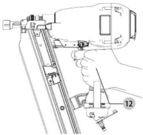
Proper Hand Position (Fig. B)
WARNING: To reduce the risk of serious personal injury, ALWAYS use proper hand position as shown. WARNING: To reduce the risk of serious personal injury, ALWAYS hold securely in anticipation of a sudden reaction.
Proper hand position requires one hand on the handle 12.
Fig. B
natural_image
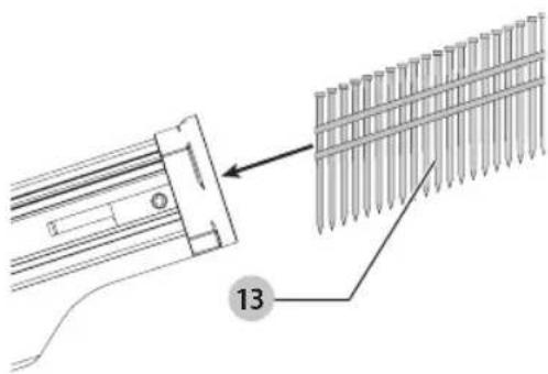
Line drawing of a hand using a power tool to install a component, labeled with number 12 (no text or symbols on the diagram itself)Loading Fasteners (Fig. C–F)
WARNING: Keep the tool pointed away from yourself and others. Serious personal injury may result. WARNING: Never load nails with the contact trip or trigger or activated. Personal injury may result.
- Disconnect the air supply to the tool.
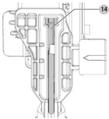
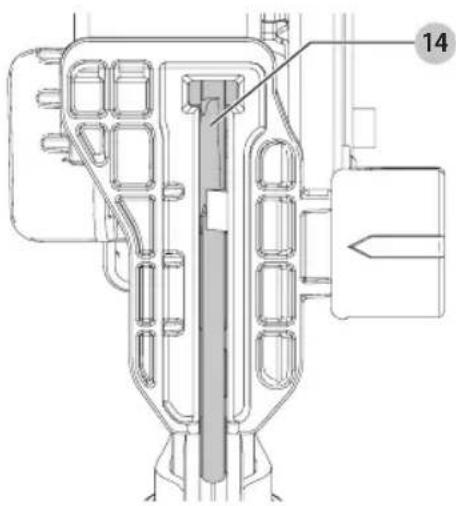
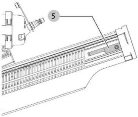
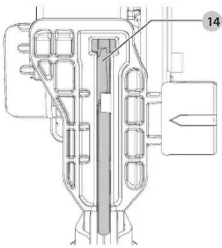
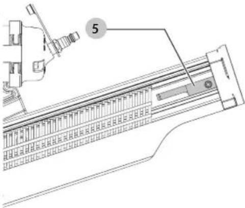
- Insert fasteners 13 into T-slot 14 on end of magazine and pull back nail stop 5.
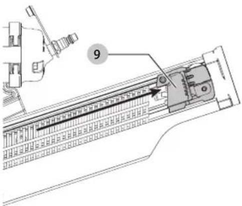
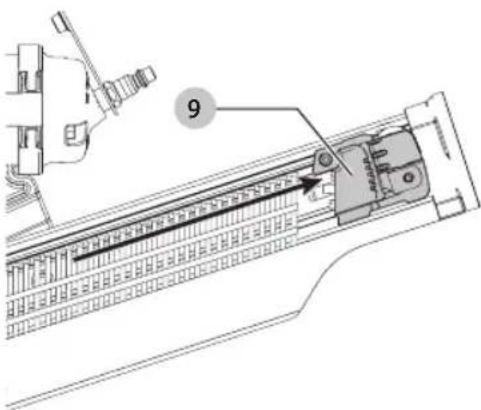
NOTE: Magazine will hold two full fastener strips. - Pull pusher 9 back until the nail stop 5 falls behind the fasteners.
Fig. C
natural_image
Technical diagram showing a mechanical component with a grid array and numbered annotation (13), no readable text or symbols present.English
Fig. D
natural_image
Technical line drawing of a mechanical component with no visible text or symbolsFig. E
natural_image
Technical line drawing of a mechanical assembly with no visible text or symbolsFig. F
NOTE: Do not allow the pusher to snap forward against the nail strip, allowing this to happen could damage the nail collation.
NOTE: This tool has a low nail lock out device which will not allow the tool to drive fasteners when the fastener quantity in the magazine is reduced to four.
Trigger
WARNING: Keep fingers AWAY from the trigger when not arriving fasteners to avoid accidental actuation. Never carry a tool with finger on the trigger. In bump action mode (contact actuation mode), the tool will
drive a fastener if the contact trip is bumped while the trigger is depressed.
The CMP21PL is equipped with a selectable trigger. This trigger allows the operator to select either single sequential action trigger mode or bump action trigger mode. In accordance with the ANSI Standard SNT-101-2015, the trigger is shipped as a single sequential action trigger mode. The selectable trigger also has a trigger lock button to keep the trigger locked at all times when the tool is not in use.
Single Sequential Actuation Trigger (Fig. G)
WARNING: Allow the tool to recoil off the work surface after actuation. If the contact trip remains depressed a nail will be driven each time the trigger is released and pulled, which could result in accidental actuation, possibly causing injury.
The single sequential trigger's intended use is for intermittent fastening where very careful and accurate placement is desired.
Contact Actuation Trigger (Fig. G)
The contact actuation trigger is intended for rapid fastening on flat, stationary surfaces.
Using the contact actuation trigger, two methods are available: place actuation and contact actuation.
Actuating Tool (Fig. G, H)
WARNING: To reduce the risk of injury, Always wear proper eye [ANSI Z87.1 (CAN/CSA Z94.3)] and hearing protection [ANSI S12.6 (S3.19)] when operating this tool.
Changing the Actuation Mode
- Push the trigger lock button 10 down.
- Rotate the mode selector button 11 counterclockwise.
- Align the triangular indicator to the desired mode.
a. For Sequential Mode as in Figure G.
b. For Contact Mode as in Figure H. - Then push the trigger lock button back up to the un-locked position.
Fig. G
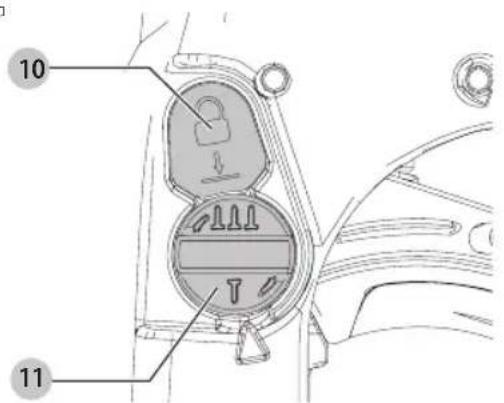
Fig. H
To Operate the Tool Using the Single Sequential Actuation Trigger
- Depress the contact trip against the work surface.
- Pull the trigger to drive the fastener.
- Allow the tool to recoil off the work surface.
WARNING: A fastener will be driven each time the trigger is pulled as long as the contact trip remains depressed which could result in accidental driving.
To Operate the Tool Using the Contact Actuation Method
- Pull the trigger.
- Depress the contact trip against the work surface. As long as the trigger is pulled, the tool will drive a fastener every time the contact trip is depressed. This allows the user to rapidly drive multiple fasteners.
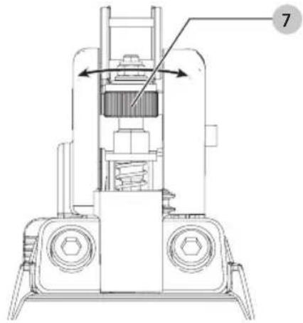
Adjusting Depth (Fig. I)
WARNING: To reduce the risk of serious personal injury, turn unit off and remove air supply before making any adjustments or removing/installing attachments or accessories. An accidental actuation can cause injury.
The depth that the fastener is driven can be adjusted using the depth adjustment wheel 7.
- To drive the fastener shallower, rotate the depth adjustment wheel to the right.
- To drive a fastener deeper, rotate the depth adjustment wheel to the left.
The adjustment knob has detents every full turn. Test drive another fastener and check depth. Repeat as necessary to achieve desired results. The amount of air pressure required will vary depending on the size of the fastener and the material being fastened.
Experiment with the air pressure setting to determine the lowest setting that will consistently perform the job at hand.
CAUTION: Air pressure in excess of that required can cause premature wear and/or damage to the tool.
Fig.1
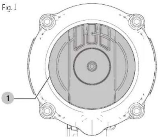
Directional Exhaust Deflector (Fig. J)
Adjust exhaust deflector 1, so the exhaust air blast will be directed away from the operator. The exhaust deflector provides sixteen detented positions for directing the exhaust blast away from the operator. Grasp the deflector and rotate it to the desired position for the current application.
natural_image
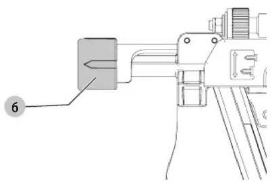
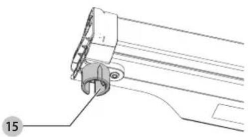
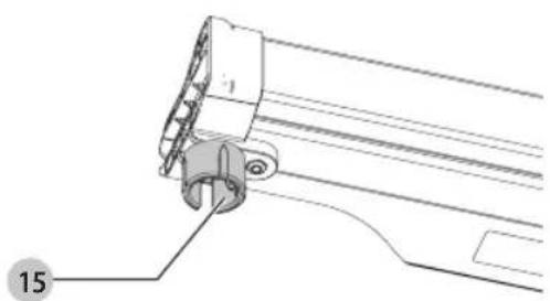
Technical diagram of a mechanical component with concentric circular features and mounting holes (no text or symbols)No-Mar Pad (Fig. K, L)
WARNING: Disconnect tool from air supply and engage trigger lock, before removing or re-installing no-mar pad.
The contact trip with no-mar pad 6 is provided to reduce marring of the work surface. The no-mar pad can be removed, and stored inside the end cap, magazine 15, to provide increased grip and depth-of-drive for toe-nailing applications.
English
Fig. K
natural_image
Technical line drawing of a mechanical device with a labeled component (no text or symbols present)Fig. L
natural_image
Technical line drawing of a mechanical component with no visible text or symbolsClearing a Jammed Fastener (Fig. M–P)
WARNING: To reduce the risk of serious personal injury, turn unit off and remove air supply before making any adjustments or removing/installing attachments or accessories. An accidental actuation can cause injury.
If a nail becomes jammed in the nose, keep the tool pointed away from you and follow these instructions to clear:
- Disconnect the tool from the air supply and engage trigger lock.
- Depress pusher release 8 and slide pusher 9 all the way to the front of the magazine.
- Depress nail stop 5 and slide fasteners 13 from magazine.
- If nail is jammed between the driver and nose force driver blade back to the top using a 1/4" (6.4 mm) punch and hammer. When the nail is released it will fall free or can be removed using pliers.
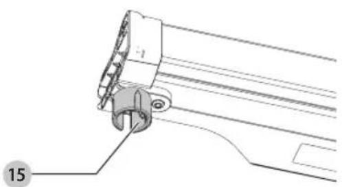
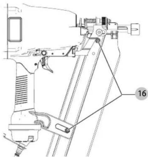
- If nail still can not be removed, remove the magazine:
a. Remove screws 16.
b. Remove magazine.
c. Remove bent nail.
d. Reassemble in reverse order.
nOTE: Should nails continue to jam frequently in nose, have tool serviced by an authorized service center.
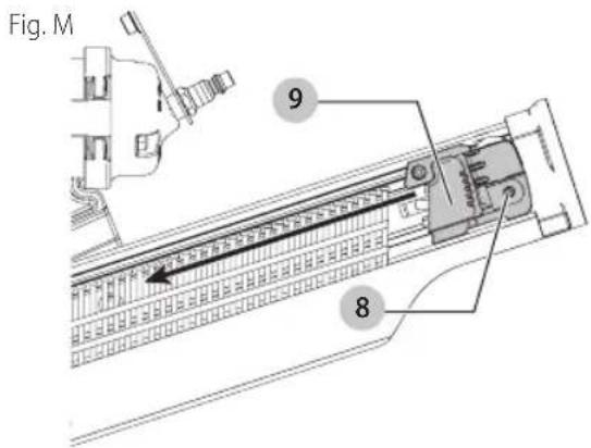
Fig. N
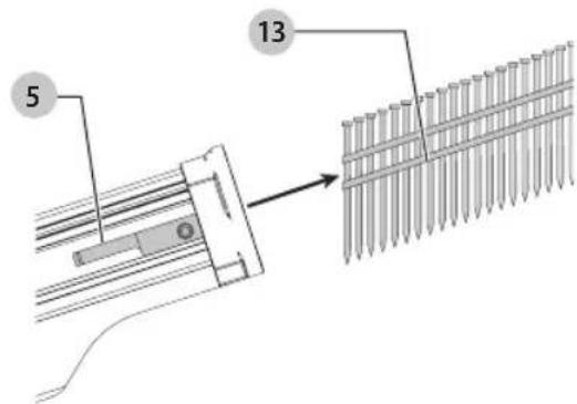
Fig. O
natural_image
Technical line drawing of a mechanical assembly with no visible text or symbols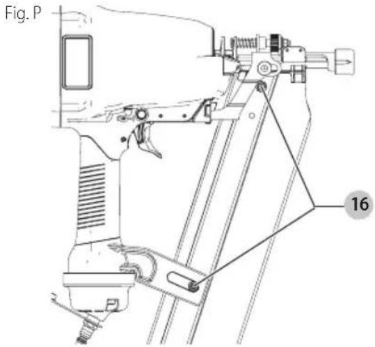
Cold Weather Operation
WARNING: To reduce the risk of serious personal injury, turn unit off and remove air supply before making any adjustments or removing/installing attachments or accessories. An accidental actuation can cause injury.
WARNING: Do not store tools in a cold weather environment to prevent frost or ice formation on the tools operating valves and mechanisms that could cause tool failure.
WARNING: Some commercial air line drying lights are harmful to "O"-rings and seals – do not use these low temperature air dryers without checking compatibility.
When operating tools at temperatures below freezing:
- Make sure compressor tanks have been properly drained prior to use.
- Keep tool as warm as possible prior to use.
- Make certain all fasteners have been removed from magazine.
- Lower air pressure to 80 p.s.i.g. (5.7 kg/cm ^2 ) or less.
- Reconnect air and and load nails into magazine.
- Actuate the tool 5 or 6 times into scrap lumber to lubricate "O"-rings.
- Turn pressure up to operating level (not to exceed 120 p.s.i.g. [8 kg/cm ^2 ]) and use tool as normal.
- Always drain the compressor tanks at least once a day.
Hot Weather Operation
Tool should operate normally. However, keep tool out of direct sunlight as excessive heat can deteriorate bumpers, o-rings and other rubber parts resulting in increased maintenance.
MAINTENANCE
WARNING: To reduce the risk of serious personal injury, turn unit off and remove air supply before making any adjustments or removing/installing attachments or accessories. An accidental actuation can cause injury.
Accessories
WARNING: Since accessories, other than those offered by CRAFTSMAN, have not been tested with this product, use of such accessories with this tool could be hazardous. To reduce the risk of injury, only CRAFTSMAN recommended accessories should be used with this product.
Recommended accessories for use with your tool are available at extra cost from your local dealer or authorized service center. If you need assistance in locating any accessory, please contact CRAFTSMAN, call 1-888-331-4569.
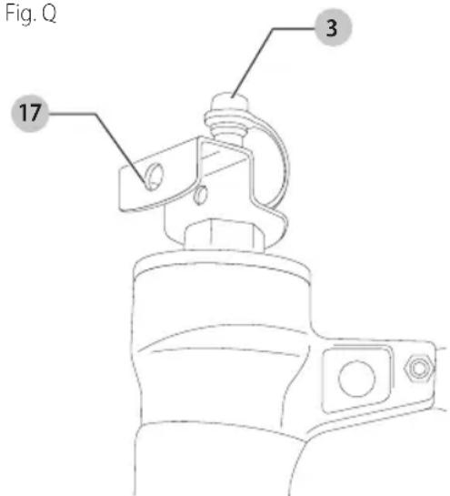
Versatrack™ (Fig. Q)
WARNING: To reduce the risk of serious personal injury, turn unit off and remove air supply before making any adjustments or removing/installing attachments or accessories. An accidental actuation can cause injury.
WARNING: To reduce the risk of serious personal injury, do not use a damaged Versatrack™ hang hook or Versatrack™ Trackwall. A damaged Versatrack™ hang hook or Versatrack™ Trackwall will not support the weight of the tool.
WARNING: To reduce the risk of serious personal injury, ensure the fitting holding the hang hook is secure.
WARNING: To reduce the risk of serious personal injury, DO NOT suspend tool overhead or suspend objects from the hang hook. ONLY suspend tool on the Versatrack™ Trackwall using the hang hook.
WARNING: Ensure that the tool weight does not add the maximum rated weight for the selected Versatrack™ hook.
WARNING: When hanging objects on a Versatrack™ Wall wall rail, adequately space the tools in order to not exceed 75 lb (35 kg) per linear foot.
iIMPORTAnT: Versatrack™ accessories mount compatible tools securely to the Versatrack™ Trackwall system.
- Turn tool off, remove air supply and remove accessories.
CANTION: Any product with exposed cutting teeth must have them covered securely if it is to be on the Versatrack™ Trackwall.
- Attach the hang hook 17 on the tool.
a. Use a wrench to remove the fitting 3.
b. Place the Versatrack™ hang hook on the fitting.
c. Use a wrench to re-install the fitting at the base of the tool.
NOTE: Versatrack™ accessories for use with your tool are available at extra cost from your local dealer or authorized
ENGLISH
service center. If you need assistance in locating any accessory, please contact CRAFTSMAN, call 1-888-331-4569.
Cleaning
WARNING: Blow dirt and dust out of all air vents with clean, dry air at least once a week. To minimize the risk of eye injury, always wear ANSI Z87.1 approved eye protection when performing this.
WARNING: Never use solvents or other harsh chemicals for cleaning the non-metallic parts of the tool. These chemicals may weaken the plastic materials used in these parts. Use a cloth dampened only with water and mild soap. Never let any liquid get inside the tool; never immerse any part of the tool into a liquid.
Repairs
WARNING: To assure product SAFETY and REELIBILITY, repairs, maintenance and adjustment (including brush inspection and replacement, when applicable) should be performed by a CRAFTSMAN factory service center or a CRAFTSMAN authorized service center. Always use identical replacement parts.
Register Online
Thank you for your purchase. Register your product now for:
- WARRANTY SERVICE: Registering your product will help you obtain more efficient warranty service in case there is a problem with your product.
- CONFIRMATION OF OWNERSHIP: In case of an insurance loss, such as fire, flood or theft, your registration of ownership will serve as your proof of purchase.
- FOR YOUR SAFETY: Registering your product will allow us to contact you in the unlikely event a safety notification is required under the Federal Consumer Safety Act.
Register online at www.craftsman.com/registration
Three Year Limited Warranty
CRAFTSMAN will repair or replace, without charge, any defects due to faulty materials or workmanship for three years from the date of purchase. This warranty does not cover part failure due to normal wear or tool abuse. For further detail of warranty coverage and warranty repair information, visit www.craftsman.com or call
1-888-331-4569. This warranty does not apply to accessories or damage caused where repairs have been made or attempted by others. THIS LIMITED WARRANTY IS GIVEN IN LIEU OF ALL OTHERS, INCLUDING THE IMPLIED WARRANTY OF MERCHANTABILITY AND FITNESS FOR A PARTICULAR PURPOSE, AND EXCLUDES ALL INCIDENTAL OR CONSEQUENTIAL DAMAGES. Some states do not allow limitations on how long an implied warranty lasts or the exclusion or limitation of incidental or consequential damages, so these limitations may not apply to you. This warranty gives you specific legal rights and you may have other rights which vary in certain states or provinces.
90 DAY MONEY BACK GUARANTEE
If you are not completely satisfied with the performance of your CRAFTSMAN Power Tool or Nailer for any reason, you can return it within 90 days from the date of purchase with a receipt for a full refund – no questions asked.
LATIN AMERICA: This warranty does not apply to products sold in Latin America. For products sold in Latin America, see country specific warranty information contained in the packaging, call the local company or see website for warranty information.
FREE WARNING LABEL REPLACEMENT: If your warning labels become illegible or are missing, call 1-888-331-4569 for a free replacement.
Troubleshooting
| Problem Cause Correction | ||
| Trigger valve housing leaks air. O-ring cut or cracked. Replace O-ring. | ||
| Trigger valve stem leaks air. O-ring/seals cut or cracked. Replace trigger valve assembly. | ||
| Frame/nose leaks air. Loose nose screws. Tighten and recheck. | ||
| O-ring or Gasket is cut or cracked. Replace O-ring or gasket. | ||
| Bumper cracked/worn. Replace bumper. | ||
| Frame/cap leaks air. Damaged gasket or seal. Replace gasket or seal. | ||
| Cracked/worn head valve bumper. Replace bumper. | ||
| Loose cap screws. Tighten and recheck. | ||
| Failure to cycle. Air supply restriction. Check air supply equipment. | ||
| Tool dry, lack of lubrication. | Use Air Tool Lubricant. | |
| Worn head valve O-rings. | Replace O-rings. | |
| Broken cylinder cap spring. | Replace cylinder cap spring. | |
| Head valve stuck in cap. | Disassemble/Check/Lubricate. | |
| Lack of power; slow to cycle. | Tool dry, lacks lubrication. | Use Air Tool Lubricant. |
| Broken cylinder cap spring. | Replace cap spring. | |
| O-rings/seals cut or cracked. | Replace O-rings/seals. | |
| Exhaust blocked . | Check bumper, head valve spring, muffler. | |
| Trigger assembly worn/leaks. | Replace trigger assembly. | |
| Dirt/tar build up on driver. | Disassemble nose/driver to clean. | |
| Cylinder sleeve not seated correctlyon bottom bumper. | Disassemble to correct. | |
| Head valve dry. | Disassemble/lubricate. | |
| Air pressure too low. | Check air supply equipment. | |
| Skipping fasteners; intermittent feed. | Worn bumper. | Replace bumper. |
| Tar/dirt in driver channel. | Disassemble and clean nose and driver. | |
| Air restriction/inadequate air flow through quick disconnect socket and plug. | Replace quick disconnect fittings. | |
| Worn piston O-ring. | Replace O-ring, check driver. | |
| Tool dry, lacks lubrication. | Use Air Tool Lubricant. | |
| Damaged pusher spring. Replace spring. | ||
| Low air pressure. | Check air supply system to tool. | |
| Loose magazine nose screws. | Tighten all screws. | |
| Fasteners too short for tool. Use only recommended fasteners. | ||
| Bent fasteners. | Discontinue using these fasteners. | |
| Wrong size fasteners. | Use only recommended fasteners. | |
| Leaking head cap gasket. | Tighten screws/replace gasket. | |
| Trigger valve O-ring cut/worn. | Replace O-ring. | |
| Broken/chipped driver. Replace driver (check piston O-ring). | ||
| Dry/dirty magazine. | Clean/lubricate use Air Tool Lubricant. | |
| Worn magazine. | Replace magazine. | |
| Fasteners jam in tool. | Driver channel worn. | Replace nose/check door. |
| Wrong size fasteners. | Use only recommended fasteners. | |
| Bent fasteners. | Discontinue using these fasteners. | |
| Loose magazine/nose screws. | Tighten all screws. | |
| Broken/chipped driver. Replace driver. | ||
DESCRIPTION
natural_image
Line drawing of a hand using a hensler to install a component, no text or symbols presentCharger des fixations (Fig. C–F)
natural_image
Technical diagram showing a mechanical assembly with a bracket and a grid-patterned structure, labeled with number 13 (no text or symbols beyond labels)Fig. D
natural_image
Technical line drawing of a mechanical component with no visible text or symbolsFRAnÇAis
Fig. E
natural_image
Technical line drawing of a mechanical assembly with no visible text or symbolsFig. F
natural_image
Cross-sectional diagram of a mechanical component with labeled part '1' (no text or symbols beyond label)Appui antimarques (Fig. K, L)
natural_image
Technical line drawing of a mechanical device with a labeled component (no text or symbols present)Fig. L
natural_image
Technical line drawing of a mechanical component with no visible text or symbolsDégagement des clous coincés (Fig. M–P)
natural_image
Technical line drawing of a mechanical assembly with no visible text or symbolsFig. P

COMPONENTES
natural_image
Technical line drawing of a hand using a power tool to install a component, labeled with number 12 (no text or symbols on the diagram itself)Cargue de la Herramienta (Fig. C–F)
natural_image
Technical diagram showing a mechanical assembly with a bracket and a grid-patterned structure, labeled with number 13 (no text or symbols beyond label)Fig. D
natural_image
Technical line drawing of a mechanical component with no visible text or symbolsEsPAÑOI
Fig. E
natural_image
Technical line drawing of a mechanical assembly with a mounted device and a numbered component (no text or symbols)Fig. F
ADVERTENCIA: A fastener will be driven each time a bigger is pulled as long as the contact trip remains depressed which could result in accidental driving.
natural_image
Technical line drawing of a mechanical assembly with no visible text or symbolsFig. L
Fig. M
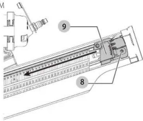
Fig. N
natural_image
Technical line drawing of a mechanical component with a numbered label (15) and no readable text or symbols.natural_image
Technical line drawing of a mechanical assembly with no visible text or symbolsFig. P
Eje Central Lázaro Cárdenas No. 18 - Local (55) 5588 9377 D, Col. Obrera
MERIDA, YUC
Calle 63 #459-A - Col. Centro (999) 928 5038
MONTERREY, N.L.
Av. Francisco I. Madero 831 Poniente - Col. (818) 375 23 13 Centro
PUEBLA, PUE
17 Norte #205 - Col. Centro (222) 246 3714
QUERETARO, QRO
Av. San Roque 274 - Col. San Gregorio (442) 2 17 63 14