
Ground Stack Kit - Monitor Chauvet - Free user manual and instructions
Find the device manual for free Ground Stack Kit Chauvet in PDF.

| Product Type | Ground mounting kit for LED video screens |
| Brand | Chauvet |
| Model | Ground Stack Kit |
| Maximum wall dimensions | Width: 1.5 m to 2 m; Height: up to 3 m |
| Platform load capacity | 113 kg (250 lb) |
| Kit weight | Approximately 25 kg (estimate) |
| Materials | Aluminum (truss AL6063), steel (jacks, pins) |
| Box contents | Transport case, 2 ground bars, 6 fixing arms, 5 ladder tubes, 4 trusses 0.5 m, 4 trusses 1 m, 8 screw jacks, climbing platform, M12 screws, REM brackets, connectors, pins, spirit level |
| Compatible panel types | REM and F series video panels (panels with centered or corner mounting holes) |
| Power supply | Passive (no power required) |
| Main functions | LED panel support, floor installation, stacking up to 3 m high, vertical orientation |
| Maintenance and cleaning | Clean with a dry cloth; check stability and weld condition before each use |
| Safety | Use by qualified personnel only; use safety equipment; ballasting required; do not use if damaged |
| Spare parts and repairability | No user-serviceable parts; contact a qualified technician for any repairs |
| Ballast required (indoor) | Yes, according to height: weights specified in the manual (e.g., 1 m: x kg, 2 m: y kg, 3 m: z kg) |
| Outdoor use | Possible with wind protection and additional ballast (according to qualified rigger) |
| Protection class (IP) | Not specified, but temporary outdoor use acceptable |
| Required tools | 3 mm hex key (for M12 screws) |
| General information | Manual available in multiple languages; lifespan: depends on use and maintenance |
Frequently Asked Questions - Ground Stack Kit Chauvet
User questions about Ground Stack Kit Chauvet
0 question about this device. Answer the ones you know or ask your own.
Ask a new question about this device
Download the instructions for your Monitor in PDF format for free! Find your manual Ground Stack Kit - Chauvet and take your electronic device back in hand. On this page are published all the documents necessary for the use of your device. Ground Stack Kit by Chauvet.
USER MANUAL Ground Stack Kit Chauvet
Ground Stack Kit
Scan the QR code to access the product page, warranty terms, and the complete User Manual
Quick Reference Guide
English EN
Español ES
Français FR
Deutsch DE
Nederlands NL
natural_image
Technical line drawing of a vertical industrial lifting platform with pipes and structural components (no text or symbols)Model ID: GROUNDSTACKKIT
Intentionally Left Blank Page
Safety Notes
These Safety Notes include important information about installation, use, and maintenance of the Ground Stack Kit.
- CAUTION:
- This product contains no user-serviceable parts.
- The climbing platform can support up to 250lbs.
- Only qualified and competent persons should use the climbing platform.
- The ballast weights stated in this specification are for indoor usage only. If this kit is used outdoors, the unit must be protected from wind and additional ballast (as determined by a qualified and competent rigger) must be used.
- This product should only be used by competent and qualified persons.
• ALWAYS:

- Use adequate safety hardware to prevent injury from falling.
- Ensure that the floor structure is stable and immobile.
- When selecting an installation location, consider ease of access for operation and routine maintenance of attached panels.
• D O N O T :
• Submerge this product (adhere to standards for the published IP rating). Regular outdoor operation is fine.
- Use the kit if any welded joints are cracked or appear damaged in any way.
- Permanently install outdoors in locations with extreme environmental conditions. This includes, but is not limited to:
- Exposure to a marine/saline environment (within 3 miles of a saltwater body of water).
- Locations where normal temperatures exceed the temperature ranges in this manual.
- Locations that are prone to flooding or being buried in snow.
• Other areas where the product will be subject to extreme radiation or caustic substances.
What is Included
• 1 Customized road case (ships prepacked)
- 2 Floor bars
• 6 Panel attachment arm
- 5 Ladder pipe with clamp
• 4 0.5M truss
• 4 1m truss
- 8 TR16 screw jack
- 1 climbing platform
• 13 M12 F-series cabinet screws - 6 REM bracket
• 13 truss double sided connector AL6063
• 25 truss pins with clip - 16in bubble level
- Quick Reference Guide
Setup
To ensure stability during operation, place ballast weights (sandbags or steel weights) evenly over the floor bars or the ladder pipe.
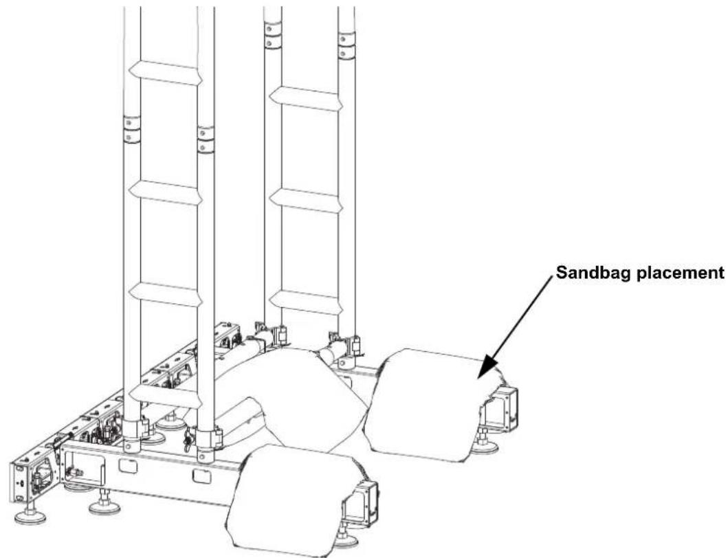
Ballast Weight Requirements
Ballast per 1M Height Stack
Ballast per 2M Height Stack
Ballast per 3M Height Stack
150 lb (68 kg) 200 lb (90.7 kg) 275 lb (124.7 kg)

The ballast weights stated in this specification are for indoor usage only. If this kit is used outdoors, the unit must be protected from wind and additional ballast (as determined by a qualified and competent rigger) must be utilized.
Mounting Procedure (REM)
The Ground Stack Kit is compatible with REM video panels. To connect the REM panels to the Ground Stack Kit:
- Attach the video panel to the rig bar panel by aligning the magnetic alignment conicals and locking the male speego connections.
- Attach the panel bracket to the carry handle of the video panel.
natural_image
Technical line drawing of a mechanical assembly with no visible text or symbols
Tighten the panel bracket with bare hands. DO NOT use tools to tighten.
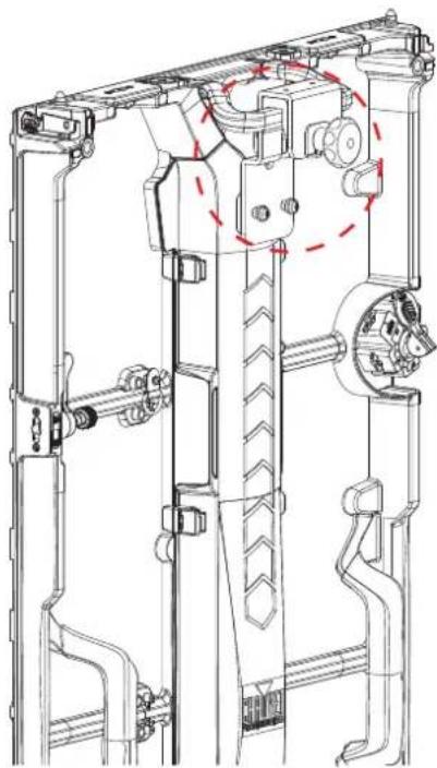
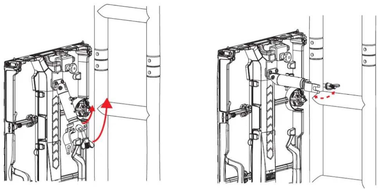
- Place the panel attachment arm over the panel attachment screws and move down to secure.
natural_image
Technical line drawing of a mechanical assembly with two views (front and side), showing internal components and alignment indicators (no text or symbols)- Secure the clamp of the panel attachment arm to the ladder truss.
natural_image
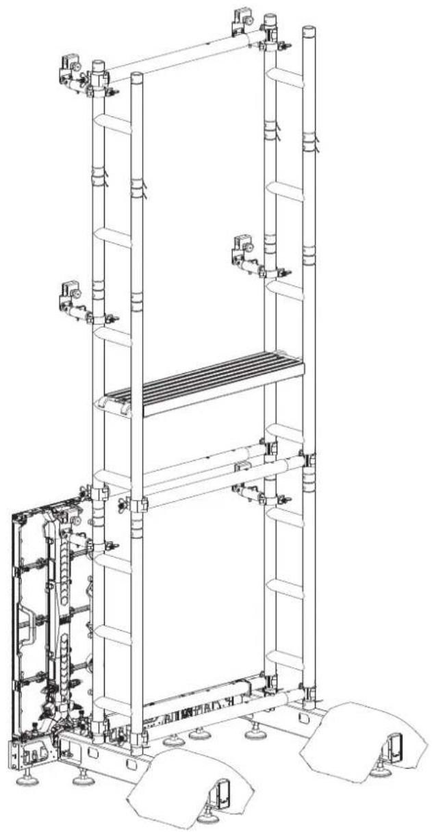
Technical line drawing of mechanical components inside a vehicle, showing internal parts and directional arrows (no text or symbols)- Continue to stack the ladder truss and video panels for the desired video wall size. Connect each panel horizontally to the panel next to it with the speego connectors. As each row of panels is added on the Ground Stack Kit, continue to ensure the entire system remains level!
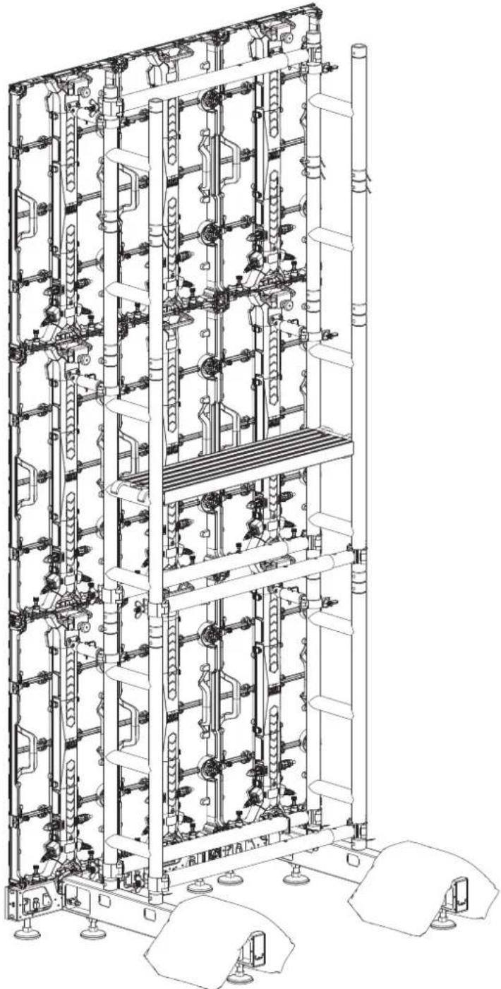
natural_image
Technical line drawing of a multi-level industrial storage or piping system with pipes and valves (no text or labels)

Supports walls between 4.92 ft (1.5 m) and 6.56 ft (2 m) wide, and as high as 9.85 ft (3 m) tall. Combine additional Ground Stack Kits to achieve wider walls.
Warning! If the rig bars and floor bases are not completely level, the Ground Stack Kit may be unstable, lean forward or backwards, or collapse. This may cause severe damage to equipment, products, flooring, or people!
Mounting Procedure (F-Series)
If the F-series video panels being used have threaded mounting holes in the center position, it is recommended to use them instead of the threaded mounting holes in the corner positions.
- Attach the F-series video panel to the rig bar panel by aligning the magnetic alignment conicals and locking the male speego connections.
- Insert the M12 panel attachment screws into the center-position M12 threaded mounting holes and secure with a 3 mm hex key.
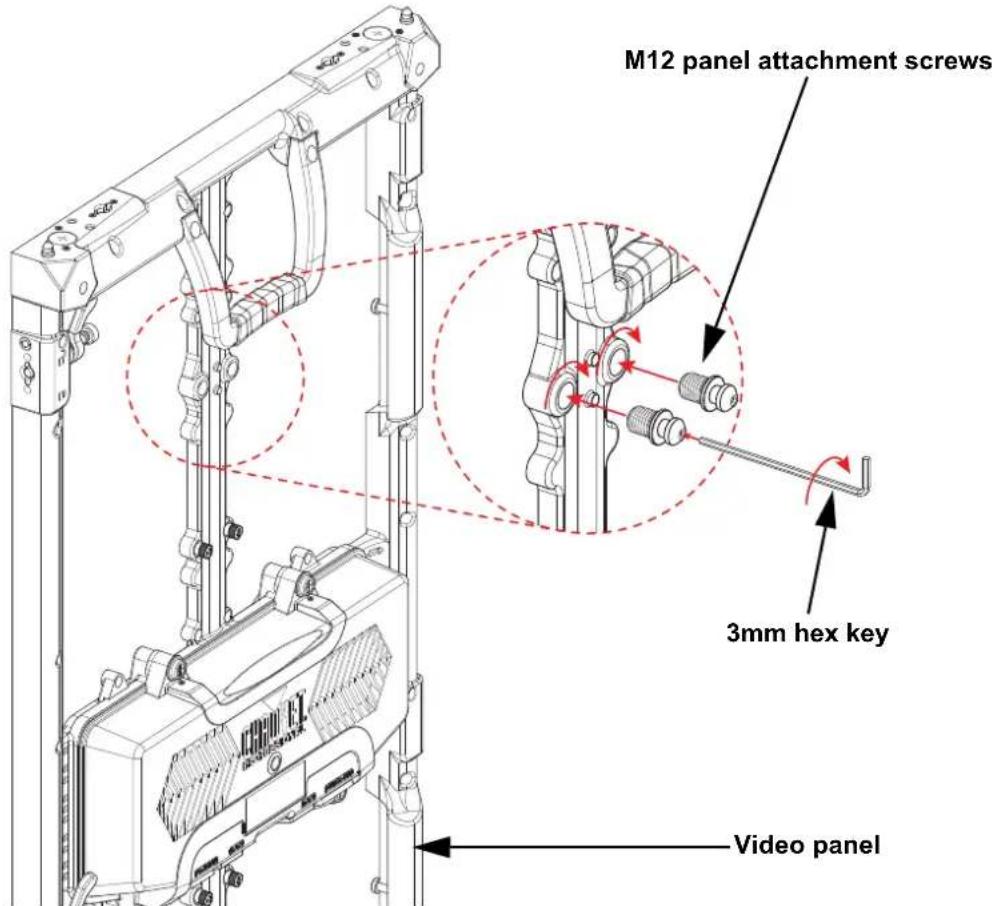

The F2 and F5IP video panels have frames with a center mounting position. The F3 video panel will need the panel attachment screw inserted at the corner of the frame. Both the F4IP and Vivid 4 have been upgraded with center mounting position frames, and may vary depending on order date.
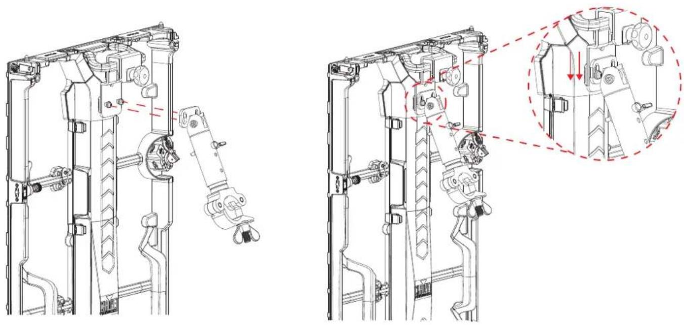
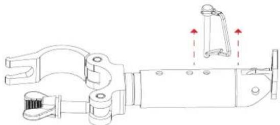
- Set the panel attachment arm to the 3rd locking level.
a. Remove the safety pin from the panel attachment arm.
natural_image
Technical line drawing of a mechanical clamp or bracket assembly with no visible text or symbolsb. Adjust the panel attachment arm to the 3rd locking level and insert/lock the safety pin.
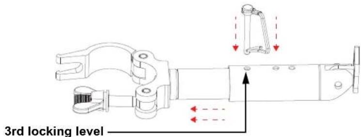
- Place the panel attachment arm over the panel attachment screws and move down to secure.
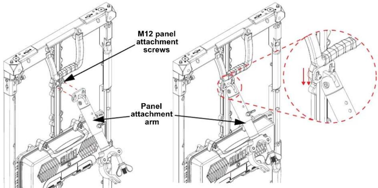
- Secure the clamp of the panel attachment arm to the ladder truss.
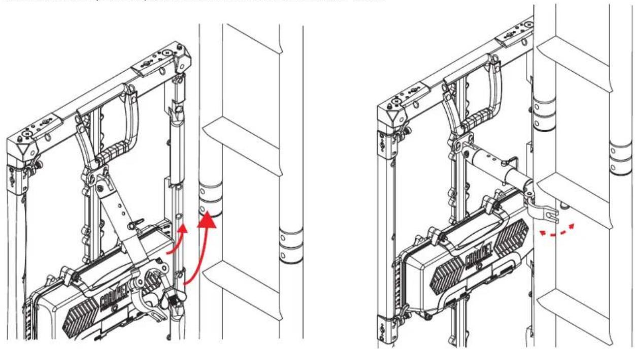
natural_image
Technical line drawing of mechanical assembly components, showing two views with red arrows indicating motion or movement (no text or symbols present)- Continue to stack the ladder truss and video panels for the desired video wall size. Connect each panel horizontally to the panel next to it with the speego connectors. As each row of panels is added on the Ground Stack Kit, continue to ensure the entire system remains level!
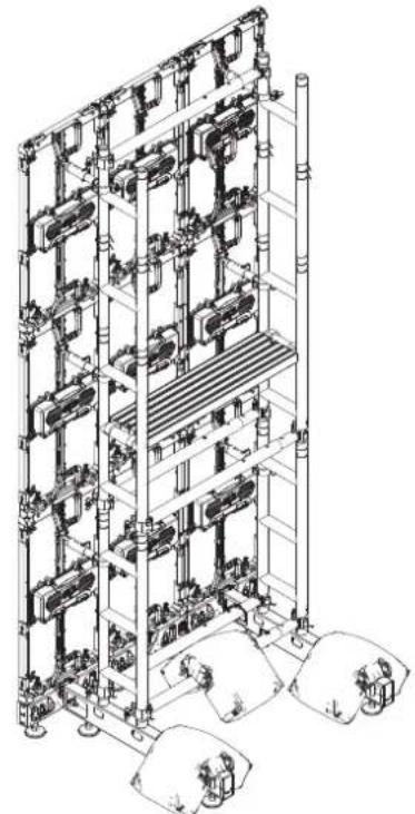
natural_image
Isometric technical line drawing of a multi-level industrial or warehouse structure with no visible text or symbols
Supports walls between 4.92 ft (1.5 m) and 6.56 ft (2 m) wide, and as high as 9.85 ft (3 m) tall. Combine additional Ground Stack Kits to achieve wider walls.

Warning! If the rig bars and floor bases are not completely level, the Ground Stack Kit may be unstable, lean forward or backwards, or collapse. This may cause severe damage to equipment, products, flooring, or people!
Notas de seguridad
150 lb (68 kg) 200 lb (90.7 kg) 275 lb (124.7 kg)

natural_image
Technical line drawing of a mechanical assembly with no visible text or symbols
natural_image
Technical line drawing of a mechanical assembly with two views (top and side), showing internal components and motion indicators (no text or symbols)natural_image
Technical line drawing of mechanical components inside a vehicle, showing internal parts and directional arrows (no text or symbols)natural_image
Technical line drawing of a multi-level industrial storage or piping system with pipes and valves (no text or labels)

natural_image
Technical line drawing of a mechanical clamp or bracket assembly (no text or symbols)natural_image
Technical line drawing of a mechanical assembly with two views (top and side), showing internal components and red directional arrows indicating motion or movement (no text or symbols present)natural_image
Isometric technical line drawing of a multi-level industrial or warehouse structure with no visible text or symbols
150 lb (68 kg) 200 lb (90.7 kg) 275 lb (124.7 kg)

natural_image
Technical line drawing of a mechanical assembly with no visible text or symbols
natural_image
Technical line drawing of a mechanical assembly with two views (front and side), showing internal components and a magnified inset highlighting a specific section (no text or symbols present)natural_image
Technical line drawing of mechanical components inside a vehicle, showing assembly and assembly details (no text or symbols)natural_image
Technical line drawing of a multi-level industrial storage or piping system with pipes and valves (no text or labels)
natural_image
Technical line drawing of a mechanical clamp or bracket assembly (no text or symbols)natural_image
Technical line drawing of a mechanical assembly with no visible text or symbols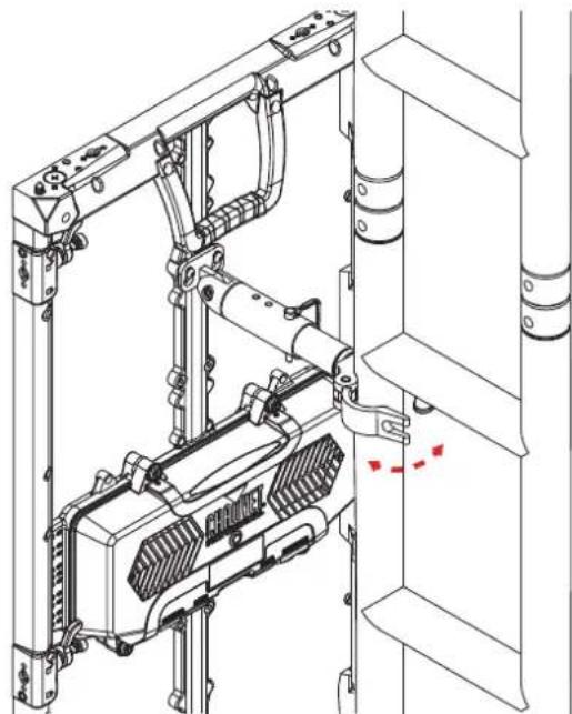
natural_image
Technical line drawing of a mechanical assembly with no visible text or symbolsnatural_image
Isometric technical line drawing of a multi-level industrial or mechanical system with no visible text, numbers, or symbols.
150 lb (68 kg) 200 lb (90.7 kg) 275 lb (124.7 kg)

natural_image
Technical line drawing of a mechanical assembly with no visible text or symbols
natural_image
Technical line drawing of a mechanical assembly with two views (front and side), showing internal components and alignment indicators (no text or symbols)natural_image
Technical line drawing of mechanical components inside a vehicle, showing internal parts and directional arrows (no text or symbols)natural_image
Technical line drawing of a multi-level industrial storage or piping system with pipes and valves (no text or labels)
natural_image
Technical line drawing of a mechanical clamp or bracket assembly (no text or symbols)natural_image
Technical line drawing of mechanical assembly components, showing two views with red arrows indicating motion or force direction (no text or symbols)natural_image
Isometric technical line drawing of a multi-level industrial or warehouse structure with no visible text or symbols
150 lb (68 kg) 200 lb (90.7 kg) 275 lb (124.7 kg)

natural_image
Technical line drawing of a mechanical assembly with no visible text or symbols
natural_image
Technical line drawing of a mechanical assembly with two views (front and side), showing internal components and a magnified inset highlighting a specific section (no text or symbols present)natural_image
Technical line drawing of mechanical components inside a vehicle, showing assembly and assembly details (no text or symbols)natural_image
Technical line drawing of a multi-level industrial storage or piping system with pipes and valves (no text or labels)
natural_image
Technical line drawing of a mechanical clamp or bracket assembly (no text or symbols)natural_image
Technical line drawing of a mechanical assembly with two views (top and side), showing internal components and red directional arrows indicating motion or movement (no text or symbols present)natural_image
Isometric technical line drawing of a multi-level industrial or mechanical system with no visible text, numbers, or symbols.
Intentionally Left Blank Page
Contact Us
General Information Technical Support
Chauvet World Headquarters
Address: 3360 Davie Rd., Suite 509 Voice: (844) 393-7575
Davie, FL 33314 Fax: (954) 756-8015
Voice: (954) 577-4455 Email: chauvetcs@chauvetlighting.com
Fax: (954) 929-5560
Toll Free: (800) 762-1084 Website: www.chauvetprofessional.com
Chauvet U.K.
Address: Pod 1 EVO Park Email: UKtech@chauvetlighting.eu
Little Oak Drive, Sherwood Park
Nottinghamshire, NG15 0EB Website: www.chauvetprofessional.eu
UK
Voice: +44 (0) 1773 511115
Fax: +44 (0) 1773 511110
Chauvet Benelux
(Entrance by Calle 2)
Zona Industrial Lerma Website: www.chauvetprofessional.mx
Visit the applicable website above to verify our contact information and instructions to request support. Outside the U.S., U.K., Ireland, Mexico, France, Germany, or Benelux, contact the dealer of record.
UK CA
CE
RoHS

- Ground Stack Kit
- Quick Reference Guide
- Safety Notes
- - CAUTION:
- • ALWAYS:
- • D O N O T :
- What is Included
- Setup
- Ballast Weight Requirements
- Mounting Procedure (REM)
- Mounting Procedure (F-Series)
- Notas de seguridad
- Intentionally Left Blank Page
- Contact Us
- General Information Technical Support
- Chauvet World Headquarters
- Chauvet U.K.
- Chauvet Benelux
Brand : Chauvet
Model : Ground Stack Kit
Category : Monitor