
Arena 10 - Loudspeaker Sonus Faber - Free user manual and instructions
Find the device manual for free Arena 10 Sonus Faber in PDF.


| Product Type | In-ceiling speaker |
| Brand | Sonus Faber |
| Model | Arena 10 |
| Category | Speaker |
| Package contents | Diffuser, fabric grilles, safety cable, protective cover, accessory box (two brackets, screws) |
| Installation | Ceiling mounting with screwed brackets, polarized audio connection, insertion and tightening |
| Audio connection | Polarized terminals, devices turned off when connecting |
| Power | Passive (requires external amplifier) |
| Distance between brackets | 824 mm (according to supplied template) |
| Approximate weight | Approximately 2-3 kg (estimate) |
| Approximate dimensions | Diameter approx. 250 mm, depth approx. 120 mm (estimate) |
| Materials | Composite material diffuser, fabric grille, metal frame |
| Care and cleaning | Dusting with soft brush, cleaning metal and glass surfaces with cloth and supplied liquid, avoid harsh chemicals |
| Safety information | Do not disassemble/modify, stable fixation, avoid high volumes nearby, keep children at 50 cm, do not connect in parallel to 100V line |
| Warranty | 2 years standard, extension possible by online registration |
| After-sales support | Contact the retailer, official distributor or email customerservice@sonusfaber.com |
| Recycling | Packaging recyclable, do not dispose of with household waste, keep out of reach of children |
Frequently Asked Questions - Arena 10 Sonus Faber
User questions about Arena 10 Sonus Faber
0 question about this device. Answer the ones you know or ask your own.
Ask a new question about this device
Download the instructions for your Loudspeaker in PDF format for free! Find your manual Arena 10 - Sonus Faber and take your electronic device back in hand. On this page are published all the documents necessary for the use of your device. Arena 10 by Sonus Faber.
USER MANUAL Arena 10 Sonus Faber
HOME CINEMA SOLUTIONS
OWNER'S MANUAL
SOMMARIO
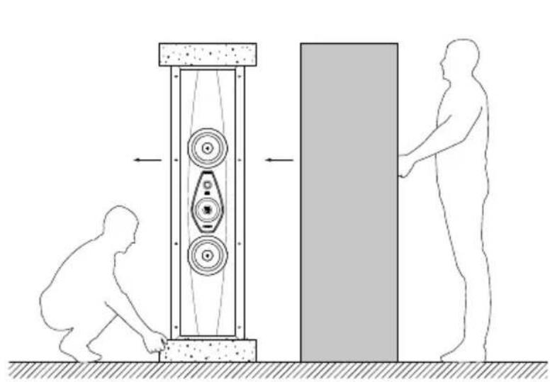
natural_image
Diagram showing two human figures interacting with a mechanical device, one moving and the other standing beside it (no text or symbols present)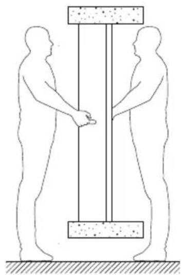
natural_image
Simple line drawing of two human figures standing under a vertical structure with a block on top (no text or symbols)3.3 - MONTAGGIO
3.3.1 - SEGNARE SULLA PARETE L'AREA DI TAGLIO MEDIANTE IL TEMPLATE IN DOTAZIONE TAGLIARE LUNGO IL PERIMETRO SEGNATO
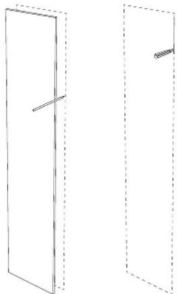
natural_image
Two simple line drawings of a door frame with dashed outlines and a diagonal line, no text or symbols present.
natural_image
Technical line drawing of a two-panel door frame structure (no text or symbols)3.3.4 - SPINGERE LE ALETTE METALLICHE A CONTATTO CON IL MURO INTERNO
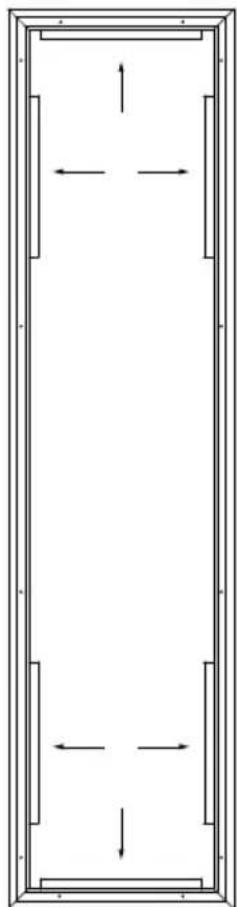
natural_image
Pure architectural floor plan lines without any text, numbers, or symbols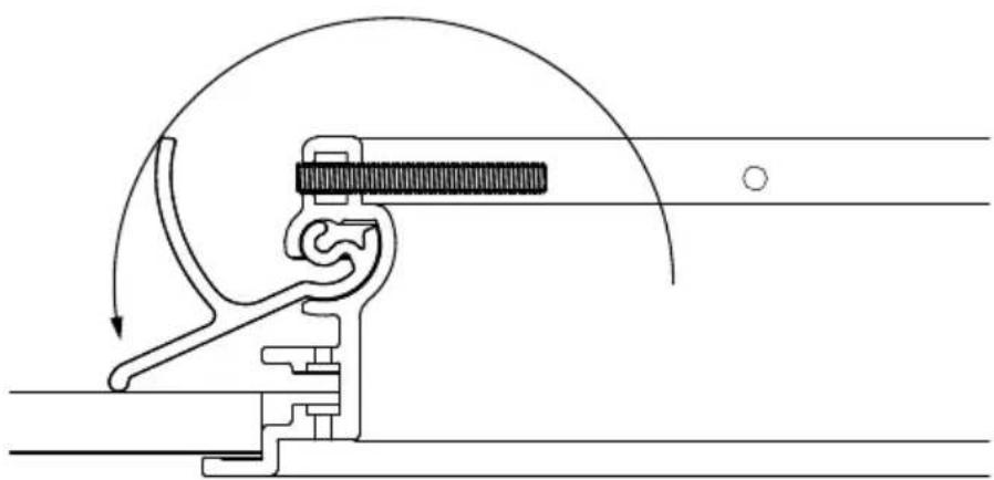
natural_image
Mechanical assembly diagram showing a lever mechanism with motion arrows (no text or labels)
natural_image
Pure technical line drawing of a mechanical component inside a rectangular frame (no text or symbols)natural_image
Technical line drawing of a mechanical clamp or tool assembly (no text or symbols)3.3.6 - INSERIRE IL DIFFUSORE ACUSTICO NELLA CORNICE
natural_image
Technical line drawing of a two-panel cabinet with circular cutouts and mounting flanges (no text or symbols)3.3.7 - AVVITARE IL DIFFUSORE ACUSTICO ALLA CORNICE CHIUDERE CON I COPRI VITI
natural_image
Simple line drawing of a cabinet or cabinet with two circular components and a lock on top (no text or symbols)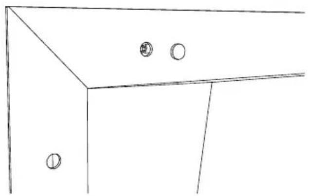
natural_image
Simple line drawing of a cabinet or cabinet with two circular fixtures on one side (no text or symbols)natural_image
Simple line drawing of a cabinet or cabinet with two circular components on top (no text or symbols)3.4.2 - SCOLLEGARE I CAVI AUDIO DAL DIFFUSORE
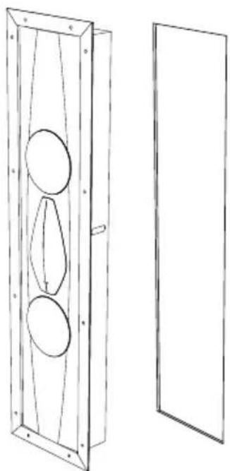
natural_image
Technical line drawing of a wall-mounted device with three circular components mounted on a wooden frame, alongside an empty rectangular panel (no text or symbols)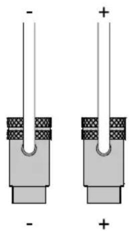
natural_image
Two identical electronic component diagrams with polarity markings, no text or symbols present3.4.3 - SVITARE LA CORNICE E ALLINEARE LE ALETTE METALLICHE RIMUOVERE LA CORNICE DAL MURO
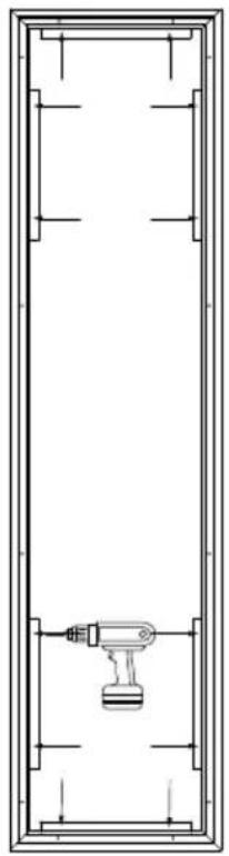
natural_image
Pure technical line drawing of a mechanical component inside a rectangular frame (no text or symbols)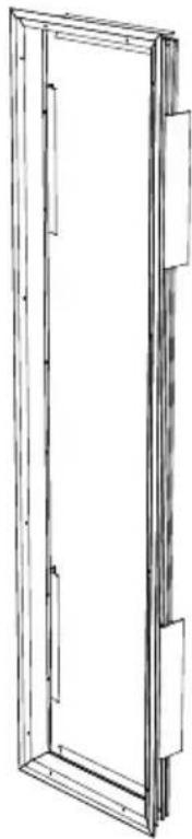
natural_image
Line drawing of a rectangular frame with internal compartments and mounting brackets (no text or symbols)
natural_image
Simple line drawing of a rectangular frame with no text or symbols
natural_image
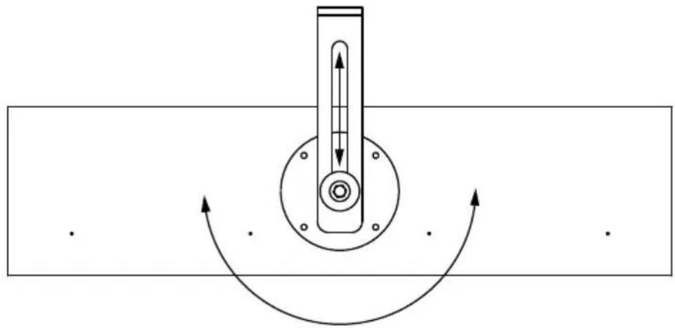
Technical line drawing of a mechanical assembly with mounting bracket and circular components (no text or symbols)4.3.4 - REGOLARE ALTEZZA E INCLINAZIONE DEL DIFFUSORE, QUINDI STRINGERE ASSICURANDO LA VITE
natural_image
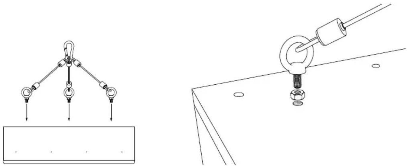
Pure mechanical diagram showing a rotating shaft and housing with curved arrows indicating motion (no text or symbols)4.3.5 - AVVITARE IL CAVO DI SICUREZZA AL DIFFUSORE ED AGGANCIARE AD UNA STRUTTURA SICURA
natural_image
Technical line drawings of two mechanical lifting or mounting mechanisms (no text or symbols present)
| ARENA 30 ARENA | 20 ARENA 10 ARENA | S15 | ||
| Speaker type 4 way | 3.5 way 3.0 way | Array Balanced Sub-Woofer | ||
| Low frequency transducer | 2 x 8 in 2 x 8 in 4 x 6.5 in 4 x 6.5 in | |||
| Mid/High frequency transducer | 2 x 6.25 in 38 mm Dome Tw + 19 mm Super Tw | 1 x 6.25 in + 19 mm Dome Tw | 1 x 6.25 in + 19 mm Tw | - |
| Maximum recommended power | 600 W 400 W 400 W 400 W | |||
| Frequency response (-6dB on-axis) | 40 Hz 32,200.0 Hz | 55 Hz 31,500.0 Hz | 36 Hz 31,585.0 Hz | 31.5 Hz 180 Hz |
| Frequency Response (-3dB on-axis) | 50 Hz 26,200.0 Hz | 60 Hz 24,710.0 Hz | 40 Hz 33,580.0 Hz | 29 Hz 180 Hz |
| Max SPL 1 Meter 120,0 dB 117,0 dB | 111.0 dB 117,0 dB | |||
| Sensitivity 2.83 Vrms@1m | 94.0 dB | 92.0 dB | 88.5 dB | 91.0 dB |
| Nominal impedance | 4 Ω | 4 Ω | 4 Ω | 4 Ω |
| Minimal impedance | 2.9 Ω 3.6 Ω | 3.5 Ω | 3.5 Ω | |
| Crossover frequencies | 200 Hz / 2k Hz / 10k Hz | 160 Hz / 220 Hz / 3100 Hz | 250 Hz / 2100 Hz | 160 Hz / 220 Hz / 3100 Hz |
| Enclosure type | Closed Box | Closed Box | Closed Box | Patent Pending Acoustical Load |
| Mounting Depth | 162 mm - 6.4 in | 144 mm - 5.7 in | 150 mm - 5.9 in | 202 mm - 7.9 in |
| Weight | 58.7 kg - 129.4 lb | 47.2 kg - 104.1 lb | 25 kg - 55.1 lb | 38.7 kg - 85.3 lb |
| Depth | 167 mm - 6.6 in | 150 mm - 5.9 in | 150 mm - 5.9 in | 208 mm - 8.1 in |
| Width | 321 mm - 12.6 in | 321 mm - 12.6 in | 590 mm - 23.2 in | 432 mm - 17 in |
| Height | 1,774 mm - 69.8 in | 1,577 mm - 62.1 in | 590 mm - 23.2 in | 947 mm - 37.2 in |
CONTENTS
- General information 16
1.1 Information for the user 16
1.2 Warranty and after sales support 16
-
Safety information 17
-
Installation (Arena 30 - Arena 20 - Arena S15) 18
3.1 Packaging contents 18
3.2 Unpacking 18
3.3 Assembly 19
3.4 Remove the loudspeaker 23
- Installation (Arena 10) 25
4.1 Packaging contents 25
4.2 Unpacking 25
4.3 Assembly 26
- Maintenance and cleaning 27
- Technical specifications 28
1. GENERAL INFORMATION
1.1 - INFORMATION FOR THE USER
Dear Customer,
We would like to thank and congratulate you on choosing Arena loudspeakers for your audio/audio-video system.
Since we want you to obtain the best possible listening result in full safety, please read this instruction manual carefully before installation.
Should you have any doubts or enquiries, please contact your sales point's technical staff, the official Sonus faber distributor in your country, or Sonus faber directly by writing to customerservice@sonusfaber.com.
Finally, we highly suggest registering on-line with the website www.sonusfaber.com in order to keep up to date on all the latest news, initiatives and promotions offered by Sonus faber. Enjoy your music!
1.2 - WARRANTY AND AFTER SALES SUPPORT
The loudspeakers are designed and manufactured according to the highest quality standards. Should however a fault or a malfunction occur, all Sonus faber products are covered by a standard warranty that covers material, technical and manufacturing defects and/or inconsistencies for two (2) years from the date of purchase by the original owner.
Please be aware that you can extend the warranty period by registering your product on https://www.sonusfaber.com/en/register-product/.
Check the complete Warranty Policy at www.sonusfaber.com/warranty-policy.
The following should also be kept in mind for your convenience:
- The warranty on the loudspeakers covers any manufacturing defects;
- Keep the receipt as proof of purchase to show to the retailer if necessary;
- Keep the loudspeakers' original packaging so that they can be transported without suffering damage if they need to be shipped to an authorized service center;
- The loudspeakers must be accompanied by a description of the malfunction or defect encountered.
The product warranty will be void under the following conditions:
- If the product has been disassembled or modified by persons other than a Sonus faber authorized service center;
- If the product has been used in a manner that is not consistent with the indications contained within this manual.
2. SAFETY INFORMATION
- This instruction manual must be read carefully and kept in an accessible location for any needs that may arise.
- Make sure that in-wall/in-ceiling fixing is suitably stable.
- Previously check that the capacity of the mounting surface is sufficient to support the weight of the loudspeaker/s.
- Avoid staying in close proximity to the loudspeakers while the audio system is operating at high volume. This can cause permanent damage to your hearing. Children must be kept at a safety distance of least 50 cm from the loudspeaker.
- The speakers generate an electromagnetic field that is harmless to humans and pets, but can compromise the proper functionality of electronic equipment, such as CRT monitors or TVs, when placed in close proximity. If this occurs, increase the equipment's distance from the loudspeakers.
- The technology underlying the speakers' functionality is based on the principles of electromagnetism, and the user should therefore avoid operating equipment that generates strong electromagnetic fields, as these could affect the loudspeaker's proper functionality.
- Do not connect the loudspeakers parallel to each other or directly to a constant voltage sound distribution system (100 V, 70.7 V or similar) without an adapter transformer. This could result in a serious system overload, with possible damage to the loudspeaker and/or the amplifier.
- Do not place audio cables and electrical power cables in close proximity to one another. An electromagnetic field is present in the vicinity of the power cables, which can cause an unpleasant humming noise. If this should occur, move the audio cables and electrical power cables away from each other.
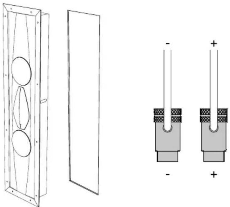
- The connections must be made with the equipment turned off. Pay attention to the polarities of the terminals during connection.
- Connect the loudspeaker to a PS1 certified source pursuant to the IEC 62368-1 Standard.
3. INSTALLATION (Arena 30 - Arena 20 - Arena S15)
3.1 - PACKAGING CONTENTS
- Speaker
- Frame
- Template for the hole
- Protective cover
- Accessories box: fabric grids, screws, screw covers.
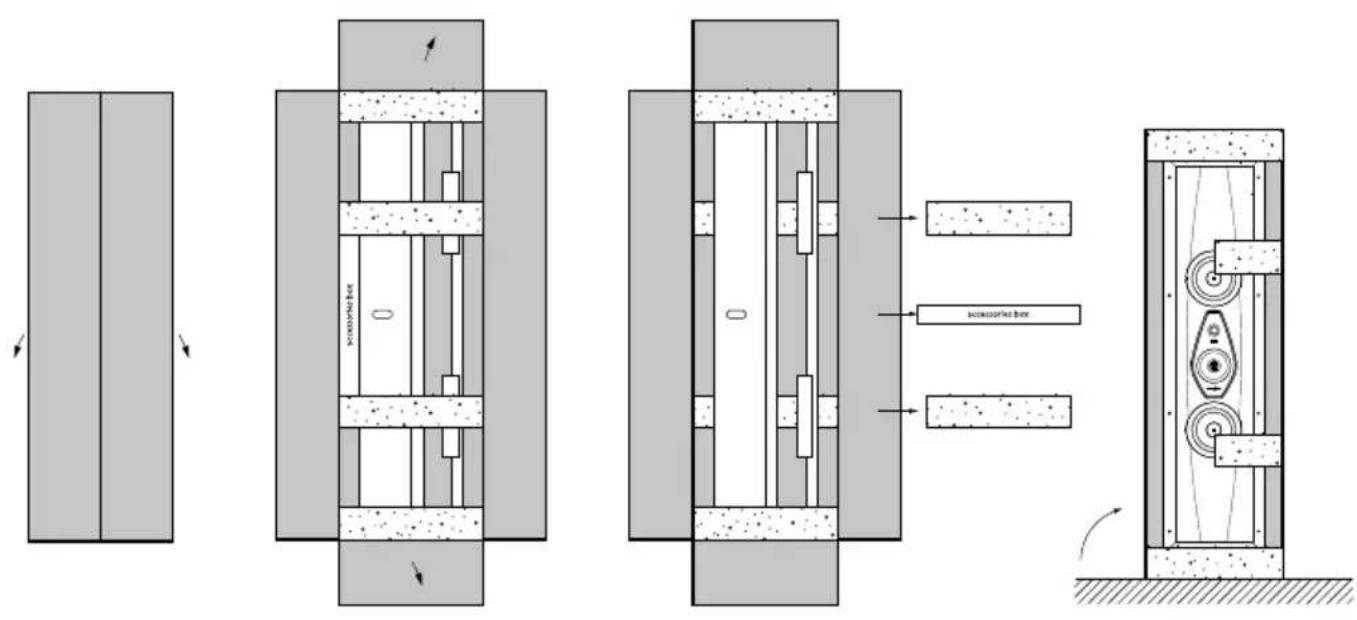
3.2 - UNPACKING
Respect the following general indications:
- It is advisable to open the packaging as close to the final location as possible.
- Use a proper tool to open the packaging. Do not insert the blade too deep to avoid damaging the contents.
- Keep all the packaging elements for any future transport operations.
- Do not wear any watches, bracelets, rings, etc., in order to avoid scratching the loudspeakers and their finishes. The same care must be taken in order to protect the loudspeakers from any metal elements present on the clothes you are wearing, such as zippers, buttons, belt clasps, rivets, etc.
- Check the content of the packaging. If one or more of the items is missing, notify the dealer where the product was purchased.
- Do not touch the drivers during the operation.
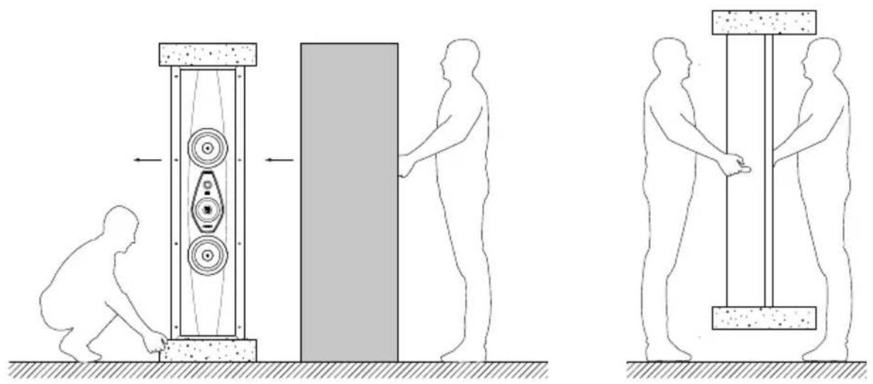
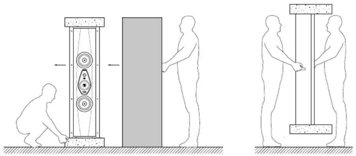
For the safe handling of the loudspeakers, it is strongly recommended to follow the instructions given in the table below:
| Up to 44 lb A person | |
| From 44 lb to 88 lb At least 2 people | |
| From 88 lb to 132 lb At least 3 people | |
| From 132 lb to 176 lb At least 4 people |

Hold the loudspeaker securely with both hands in order to avoid dropping it.
The packaging materials can cause pollution. These materials must not be disposed of as domestic waste and must be brought to a waste collection and recycling center.
Do not leave the packaging materials within the reach of children! They could pose a risk of poisoning or suffocation if ingested.
If using a dedicated stand, do not use it with any speaker system other than the one for which it was designed. Improper use of the stand can result in damage or injury.
EN
natural_image
Three sequential diagrams showing human figures interacting with a vertical structure and a weight, illustrating mechanical or structural changes (no text or symbols present)3.3 - ASSEMBLY
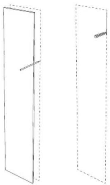
3.3.1 - MARK THE AREA TO BE CUT ON THE WALL USING THE TEMPLATE SUPPLIED
natural_image
Two simple line drawings of a door frame with dashed outlines and internal lines, no text or symbols present.
Previously, make sure that the cutting area is between the two uprights!
For correct operation of the fixing system, maintain a distance of at least 4 cm between the lateral edge of the hole and the nearest upright.

Pay attention to the polarities of the terminals during connection.
The connections must be made with the equipment turned off!
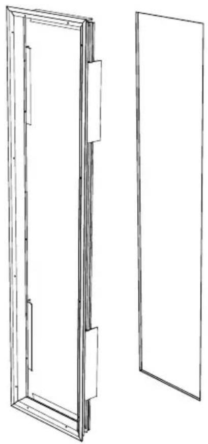
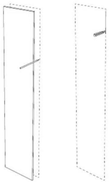
3.3.3 - INSERT THE FRAME IN THE DRILLED HOLE
natural_image
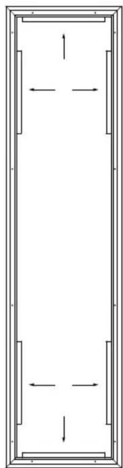
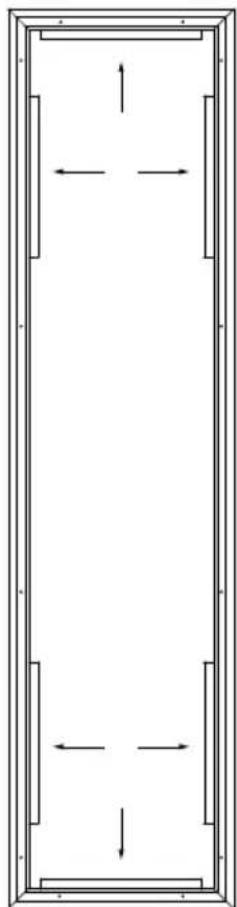
Technical line drawing of a two-panel door frame structure (no text or symbols)3.3.4 - PUSH THE METALLIC FINS INTO CONTACT WITH THE INTERNAL WALL
natural_image
Pure architectural floor plan lines without any text, numbers, or symbols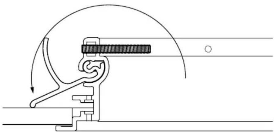
natural_image
Mechanical assembly diagram showing a lever mechanism with motion arrows (no text or labels)| Remove the rubber bands |
3.3.5 - SCREW THE FRAME
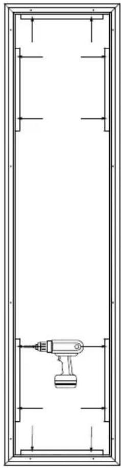
natural_image
Pure technical diagram of a mechanical component inside a rectangular frame, without any text, numbers, or symbols.
Tighten the locking screws fully home without force, to prevent damage to the locking system!
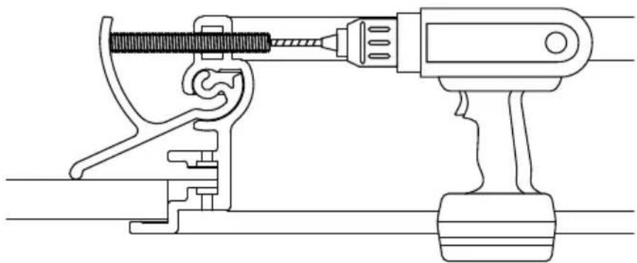
natural_image
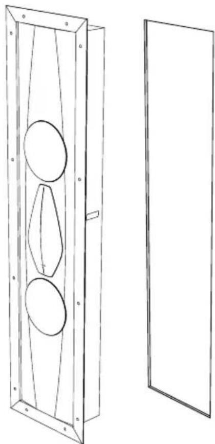
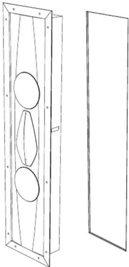
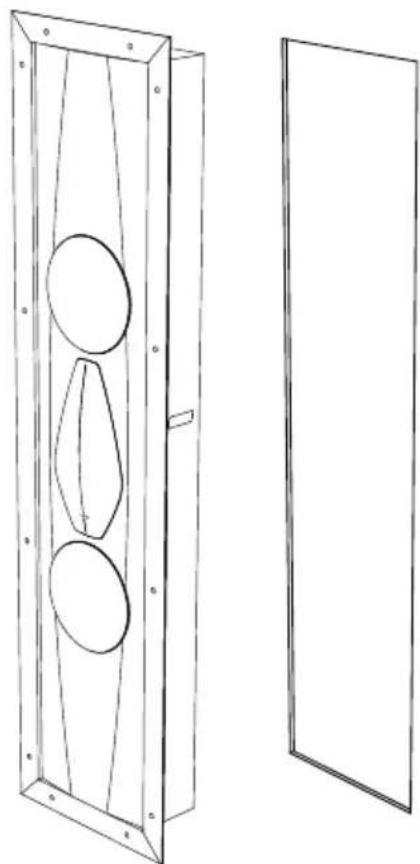
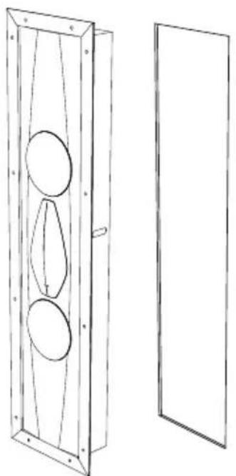
Technical line drawing of a mechanical clamp or tool assembly (no text or symbols)3.3.6 - INSERT THE LOUDSPEAKER IN THE FRAME
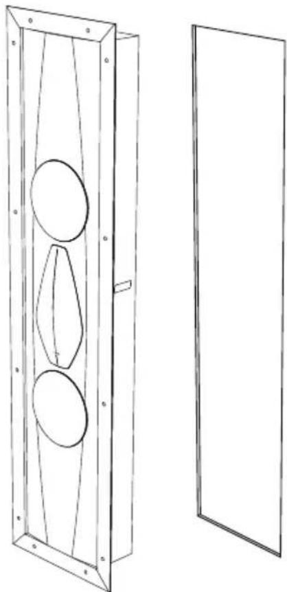
natural_image
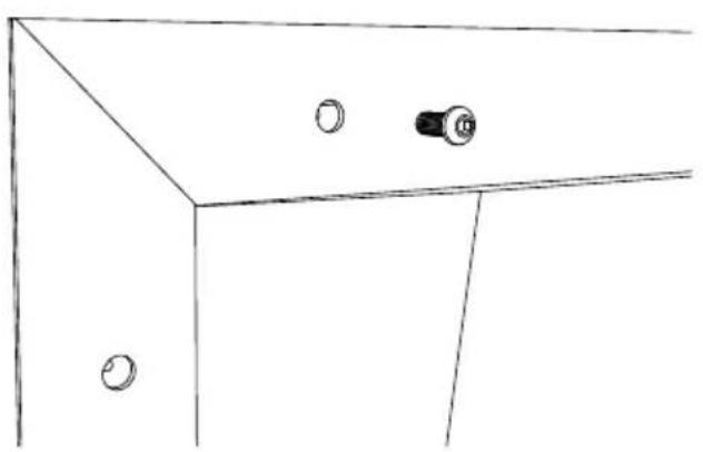
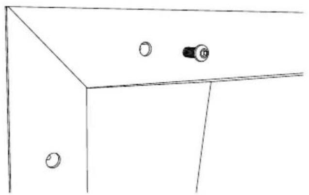
Technical line drawing of a two-panel cabinet with circular cutouts and mounting flanges (no text or symbols)3.3.7 - SCREW THE LOUDSPEAKER TO THE FRAME CLOSE WITH THE SCREW COVERS
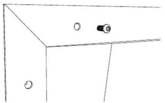
natural_image
Simple line drawing of a cabinet or cabinet with two circular components and a central knob (no text or symbols)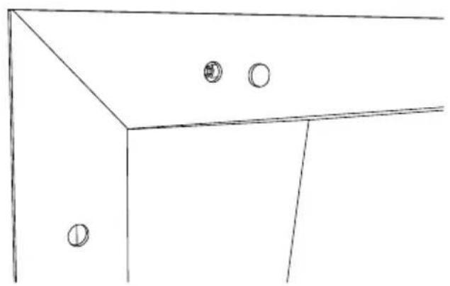
natural_image
Simple line drawing of a cabinet or cabinet with two circular fixtures on one side (no text or symbols)3.4 - REMOVE THE LOUDSPEAKER
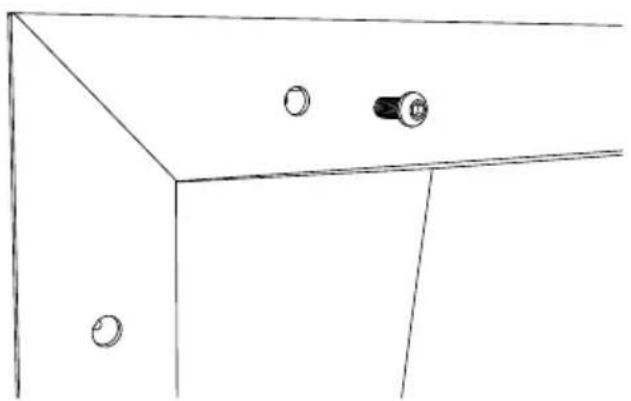
3.4.1 - UNSCREW THE LOUDSPEAKER FROM THE FRAME
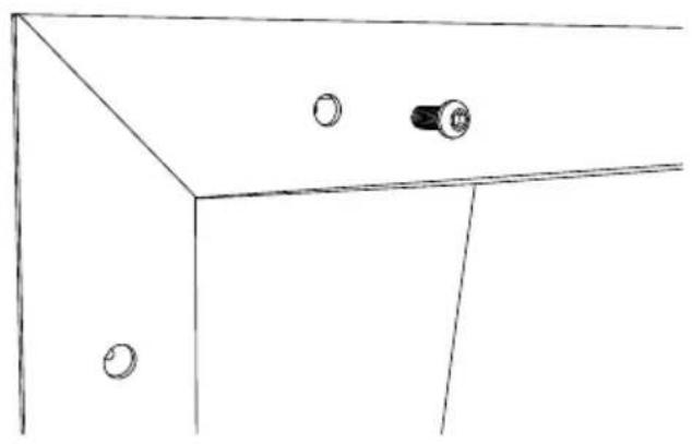
natural_image
Simple line drawing of a cabinet with two circular fixtures on one side (no text or symbols)natural_image
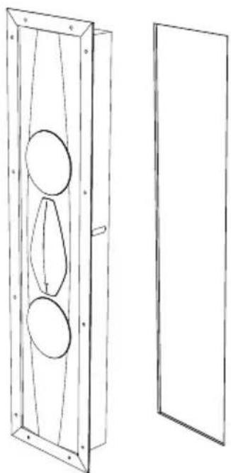
Technical line drawing of a wooden cabinet with three circular cutouts and two empty panels (no text or symbols)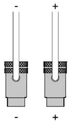
natural_image
Two identical electronic component diagrams with polarity markings, no text or symbols present3.4.3 - UNSCREW THE FRAME AND ALIGN THE METAL FINS REMOVE THE FRAME FROM THE WALL
Perform the operation with the appliances off!
4. INSTALLATION (Arena 10)
4.1 - PACKAGING CONTENTS
- Speaker
- Fabric meshes
- Safety cable
- Protective cover
- Accessory box: Two brackets, screws.
4.2 - UNPACKING
Respect the following general indications:
- It is advisable to open the packaging as close to the final location as possible.
- Use a proper tool to open the packaging. Do not insert the blade too deep to avoid damaging the contents.
- Keep all the packaging elements for any future transport operations.
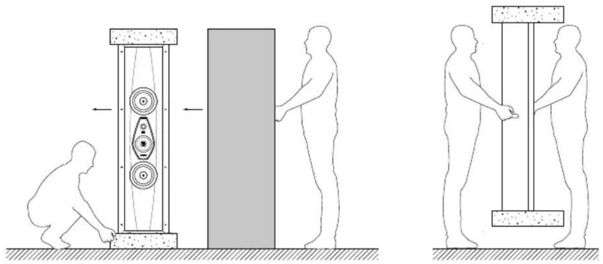
- Do not wear any watches, bracelets, rings, etc., in order to avoid scratching the loudspeakers and their finishes. The same care must be taken in order to protect the loudspeakers from any metal elements present on the clothes you are wearing, such as zippers, buttons, belt clasps, rivets, etc.
- Check the content of the packaging. If one or more of the items is missing, notify the dealer where the product was purchased.
- Do not touch the drivers during the operation.
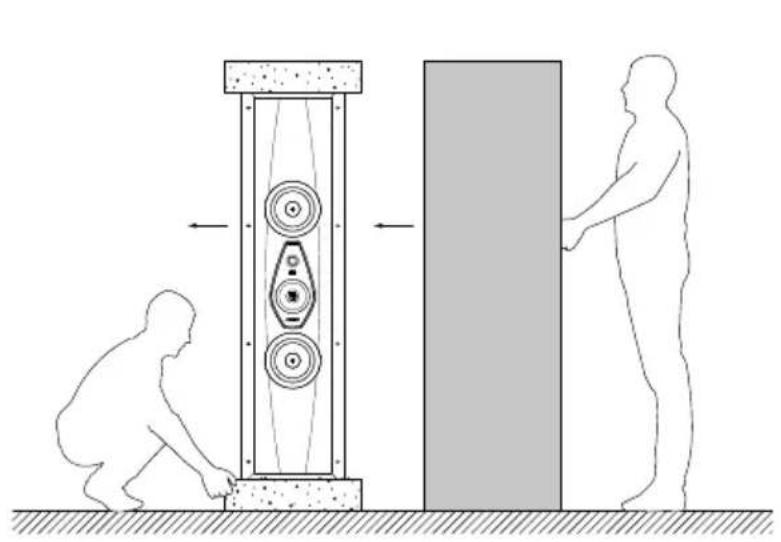
For the safe handling of the loudspeakers, it is strongly recommended to follow the instructions given in the table below:
| Up to 44 lb A person | |
| From 44 lb to 88 lb At least 2 people | |
| From 88 lb to 132 lb At least 3 people | |
| From 132 lb to 176 lb At least 4 people |

Hold the loudspeaker securely with both hands in order to avoid dropping it.
The packaging materials can cause pollution. These materials must not be disposed of as domestic waste and must be brought to a waste collection and recycling center.
Do not leave the packaging materials within the reach of children! They could pose a risk of poisoning or suffocation if ingested.
If using a dedicated stand, do not use it with any speaker system other than the one for which it was designed. Improper use of the stand can result in damage or injury.
4.3 - ASSEMBLY
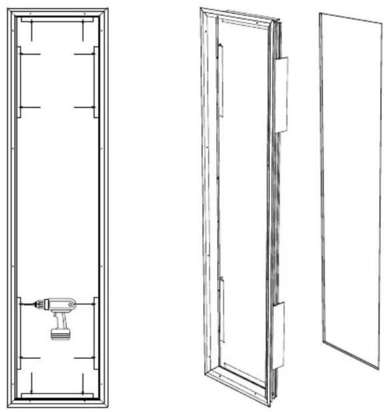
4.3.1 - SCREW THE TWO BRACKETS TO THE CEILING AT THE DISTANCE SHOWN IN THE TEMPLATE PROVIDED
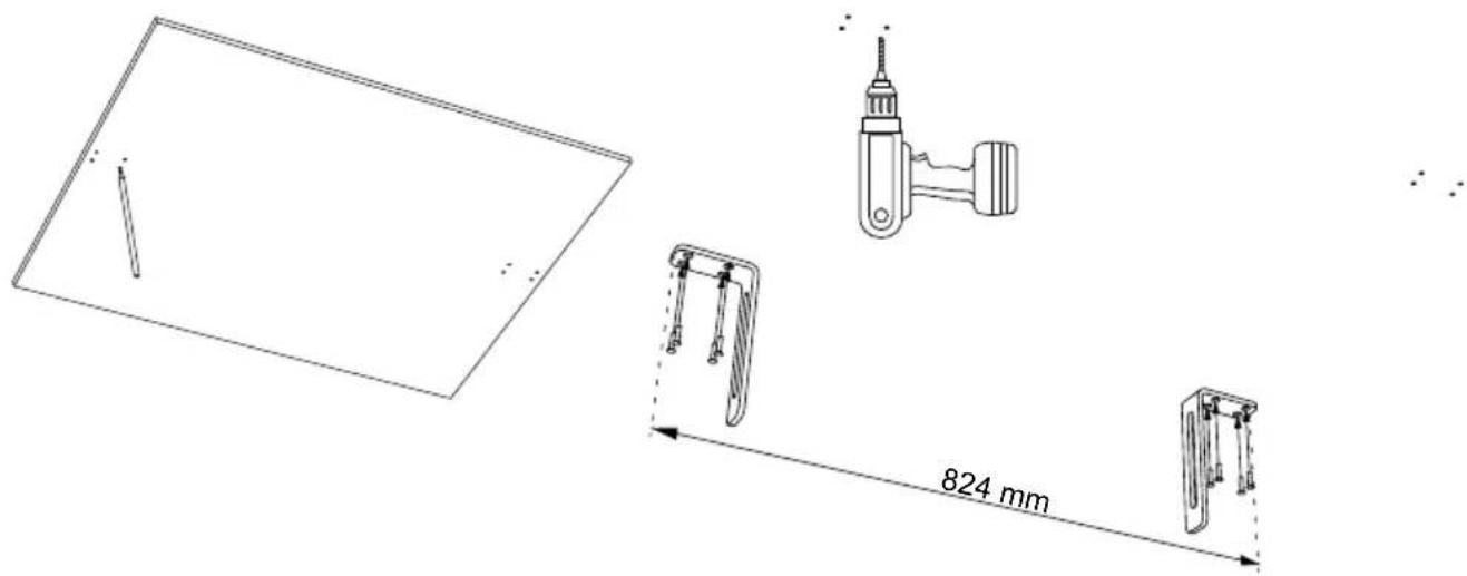

Pay attention to the polarities of the terminals during connection.
The connections must be made with the equipment turned off!
4.3.3 - FIT THE SPEAKER AND TIGHTEN THE SCREW AND WASHER ON BOTH SIDES
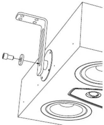
natural_image
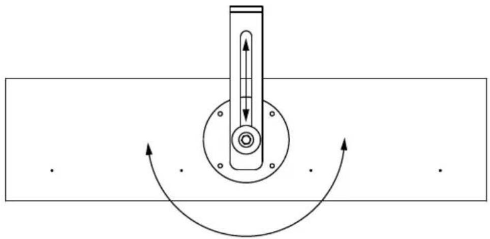
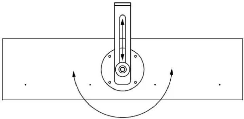
Technical line drawing of a mechanical bracket assembly with mounting holes and a flange (no text or symbols)4.3.4 - ADJUST THE HEIGHT AND INCLINATION OF THE SPEAKER, THEN TIGHTEN SECURING THE SCREW
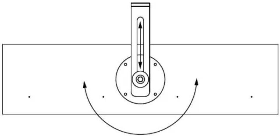
natural_image
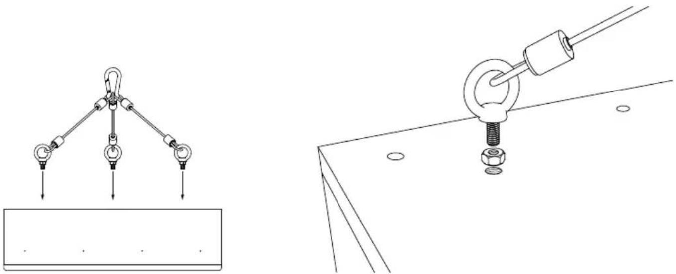
Pure mechanical diagram showing a rotating shaft and housing with curved arrows indicating motion (no text or symbols)4.3.5 – SCREW THE SAFETY CABLE TO THE SPEAKER AND LATCH ON TO A STABLE STRUCTURE
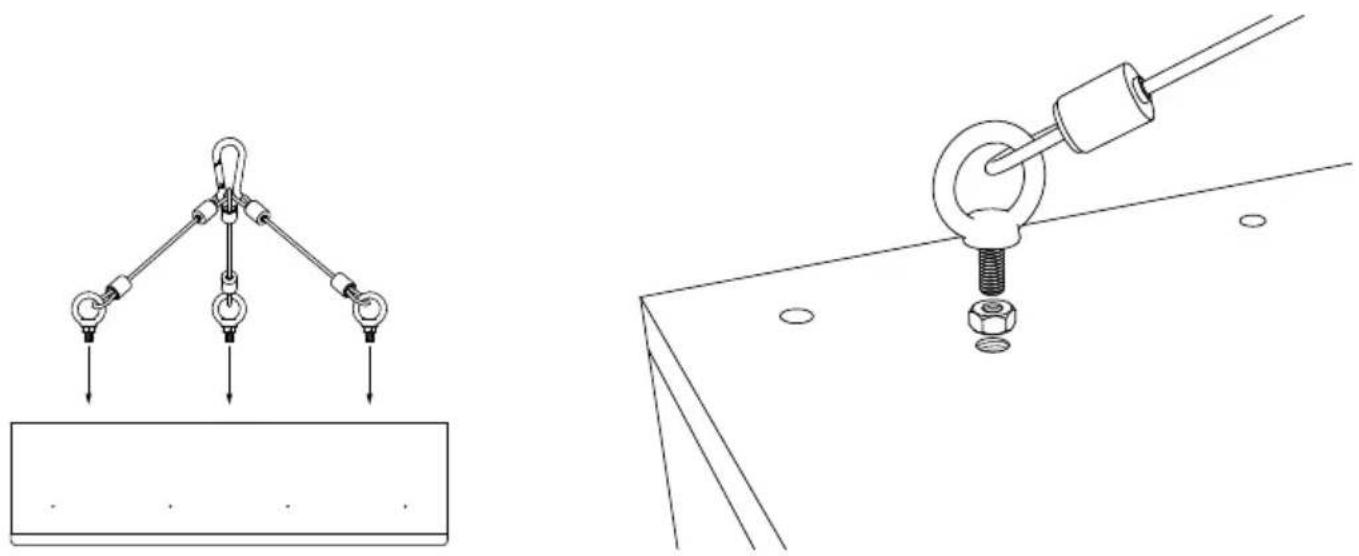
natural_image
Technical line drawings of mechanical lifting and mounting components (no text or symbols)
Perform the operation with the appliances off!
5. MAINTENANCE AND CLEANING
The loudspeakers do not require any particular maintenance operations, just general periodic cleaning.
It is recommended to use a soft brush to eliminate any dust that may have accumulated on the cabinet, the front panels, and the loudspeakers themselves, taking care not to damage the loudspeakers' delicate membranes.
It is recommended to use the supplied cloth and liquid to clean the metal and glass surfaces (where present). Do not use aggressive strong chemical products such as acetone, trichloroethylene, acids, abrasive agents, strong de-greasers, alcohol, lemon or wine. These measures will help you to keep your loudspeakers' working perfectly for years to come. Time will help improve the sound by breaking in the speakers' moving parts (membranes and suspensions), and the acoustic chamber will become accustomed to music being played the more it is used - much like what happens with acoustic string instruments!
6. TECHNICAL SPECIFICATIONS
| ARENA 30 ARENA | 20 ARENA 10 ARENA | S15 | ||
| Speaker type 4 way | 3.5 way 3.0 way | Array Balanced Sub-Woofer | ||
| Low frequency transducer | 2 x 8 in 2 x 8 in 4 x 6.5 in 4 x 6.5 in | |||
| Mid/High frequency transducer | 2 x 6.25 in 38 mm Dome Tw + 19 mm Super Tw | 1 x 6.25 in + 19 mm Dome Tw | 1 x 6.25 in + 19 mm Tw | - |
| Maximum recommended power | 600 W 400 W 400 W 400 W | |||
| Frequency response (-6dB on-axis) | 40 Hz 32,200.0 Hz | 55 Hz 31,500.0 Hz | 36 Hz 31,585.0 Hz | 31.5 Hz 180 Hz |
| Frequency Response (-3dB on-axis) | 50 Hz 26,200.0 Hz | 60 Hz 24,710.0 Hz | 40 Hz 33,580.0 Hz | 29 Hz 180 Hz |
| Max SPL 1 Meter 120,0 dB 117,0 dB | 111.0 dB 117,0 dB | |||
| Sensitivity 2.83 Vrms@1m | 94.0 dB | 92.0 dB | 88.5 dB | 91.0 dB |
| Nominal impedance | 4 Ω | 4 Ω | 4 Ω | 4 Ω |
| Minimal impedance | 2.9 Ω 3.6 Ω | 3.5 Ω | 3.5 Ω | |
| Crossover frequencies | 200 Hz / 2k Hz / 10k Hz | 160 Hz / 220 Hz / 3100 Hz | 250 Hz / 2100 Hz | 160 Hz / 220 Hz / 3100 Hz |
| Enclosure type | Closed Box | Closed Box | Closed Box | Patent Pending Acoustical Load |
| Mounting Depth | 162 mm - 6.4 in | 144 mm - 5.7 in | 150 mm - 5.9 in | 202 mm - 7.9 in |
| Weight | 58.7 kg - 129.4 lb | 47.2 kg - 104.1 lb | 25 kg - 55.1 lb | 38.7 kg - 85.3 lb |
| Depth | 167 mm - 6.6 in | 150 mm - 5.9 in | 150 mm - 5.9 in | 208 mm - 8.1 in |
| Width | 321 mm - 12.6 in | 321 mm - 12.6 in | 590 mm - 23.2 in | 432 mm - 17 in |
| Height | 1,774 mm - 69.8 in | 1,577 mm - 62.1 in | 590 mm - 23.2 in | 947 mm - 37.2 in |
SOMMAIRE
- Installation (Arena 10) 38

natural_image
Three sequential illustrations showing human figures interacting with a mechanical device, illustrating mechanical or electrical assembly (no text or symbols present)3.3 - MONTAGE
3.3.1 - MARQUER LA ZONE DE COUPE SUR LE MUR EN UTILISANT LE GABARIT FOURNI EN DOTATION DÉCOUPER LE LONG DU PÉRIMÈTRE TRACÉ
natural_image
Two simple line drawings of a door frame with dashed outlines and a diagonal line, no text or symbols present.
natural_image
Technical line drawing of a two-panel door frame structure (no text or symbols)FR
3.3.4 - POUSSER LES AILETTES MÉTALLIQUES EN CONTACT AVEC LA PAROI INTÉRIEURE
natural_image
Pure architectural floor plan lines without any text, numbers, or symbols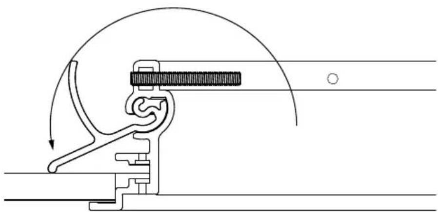
natural_image
Mechanical assembly diagram showing a lever mechanism with motion arrows (no text or labels)
natural_image
Pure technical line drawing of a mechanical component inside a rectangular frame (no text or symbols)
natural_image
Technical line drawing of a mechanical clamp or tool assembly (no text or symbols)3.3.6 - INSÉRER L'ENCEINTE ACOUSTIQUE DANS LE CADRE
natural_image
Technical line drawing of a two-panel cabinet with circular cutouts and mounting flanges (no text or symbols)3.3.7 - VISSER L'ENCEINTE AU CADRE ET FERMER AVEC LES CACHE-VIS
natural_image
Simple line drawing of a cabinet or cabinet with two circular components and a central knob (no text or symbols)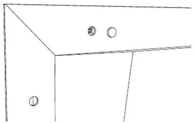
natural_image
Simple line drawing of a cabinet or cabinet with two circular fixtures on one side (no text or symbols)natural_image
Simple line drawing of a cabinet with two circular fixtures and a handle (no text or symbols)3.4.2 - DÉCONNECTER LES CÂBLES AUDIO DE L'ENCEINTE
natural_image
Technical diagram showing two views of a door frame with circular cutouts, alongside two labeled mechanical components with polarity indicators (no text or symbols present)3.4.3 - DÉVISSER LE CADRE ET ALIGNER LES AILETTES MÉTALLIQUES RETIRER LE CADRE DU MUR




natural_image
Technical line drawing of a mechanical assembly with mounting bracket and circular components (no text or symbols)4.3.4 – RÉGLER LA HAUTEUR ET L'INCLINAISON DE L'ENCEINTE, PUIS SERRER EN FIXANT LA VIS
natural_image
Pure mechanical diagram showing a rotating shaft and housing with curved arrows indicating motion (no text or symbols)4.3.5 – VISSER LE CÂBLE DE SÉCURITÉ À L'ENCEINTE ET LE FIXER À UNE STRUCTURE SÉCURISÉE

natural_image
Technical line drawings of mechanical lifting and mounting components (no text or symbols)
| ARENA 30 ARENA | 20 ARENA 10 ARENA | S15 | ||
| Speaker type 4 way | 3.5 way 3.0 way | Array Balanced Sub-Woofer | ||
| Low frequency transducer | 2 x 8 in 2 x 8 in 4 x 6.5 in 4 x 6.5 in | |||
| Mid/High frequency transducer | 2 x 6.25 in 38 mm Dome Tw + 19 mm Super Tw | 1 x 6.25 in + 19 mm Dome Tw | 1 x 6.25 in + 19 mm Tw | - |
| Maximum recommended power | 600 W 400 W 400 W 400 W | |||
| Frequency response (-6dB on-axis) | 40 Hz 32,200.0 Hz | 55 Hz 31,500.0 Hz | 36 Hz 31,585.0 Hz | 31.5 Hz 180 Hz |
| Frequency Response (-3dB on-axis) | 50 Hz 26,200.0 Hz | 60 Hz 24,710.0 Hz | 40 Hz 33,580.0 Hz | 29 Hz 180 Hz |
| Max SPL 1 Meter 120,0 dB 117,0 dB | 111.0 dB 117,0 dB | |||
| Sensitivity 2.83 Vrms@1m | 94.0 dB | 92.0 dB | 88.5 dB | 91.0 dB |
| Nominal impedance | 4 Ω | 4 Ω | 4 Ω | 4 Ω |
| Minimal impedance | 2.9 Ω 3.6 Ω | 3.5 Ω | 3.5 Ω | |
| Crossover frequencies | 200 Hz / 2k Hz / 10k Hz | 160 Hz / 220 Hz / 3100 Hz | 250 Hz / 2100 Hz | 160 Hz / 220 Hz / 3100 Hz |
| Enclosure type | Closed Box | Closed Box | Closed Box | Patent Pending Acoustical Load |
| Mounting Depth | 162 mm - 6.4 in | 144 mm - 5.7 in | 150 mm - 5.9 in | 202 mm - 7.9 in |
| Weight | 58.7 kg - 129.4 lb | 47.2 kg - 104.1 lb | 25 kg - 55.1 lb | 38.7 kg - 85.3 lb |
| Depth | 167 mm - 6.6 in | 150 mm - 5.9 in | 150 mm - 5.9 in | 208 mm - 8.1 in |
| Width | 321 mm - 12.6 in | 321 mm - 12.6 in | 590 mm - 23.2 in | 432 mm - 17 in |
| Height | 1,774 mm - 69.8 in | 1,577 mm - 62.1 in | 590 mm - 23.2 in | 947 mm - 37.2 in |
INHALTSVERZEICHNIS
- Installation (Arena 10) 51
4.1 Packungsinhalt 51
4.2 Auspacken 51
4.3 Montage 52
natural_image
Diagram showing two human figures interacting with a vertical mechanical device, one assisting the other (no text or symbols present)
natural_image
Simple line drawing of two human figures standing under a vertical structure with a block, no text or symbols present.3.3 - MONTAGE
natural_image
Two simple line drawings of a door frame with dashed outlines and a diagonal line, no text or symbols present.natural_image
Technical line drawing of a two-panel door frame structure (no text or symbols)natural_image
Pure architectural floor plan lines without any text, numbers, or symbols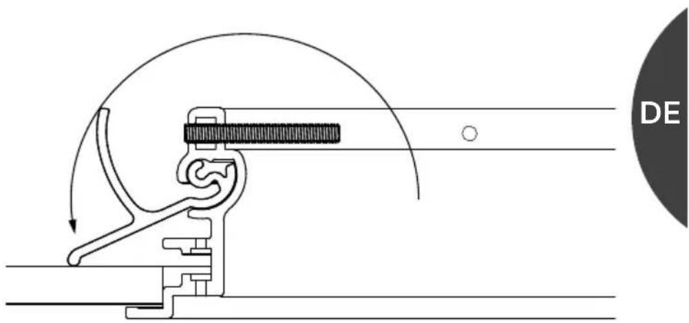
natural_image
Pure technical diagram of a mechanical device inside a rectangular frame, without any text, numbers, or symbols.
natural_image
Technical line drawing of a mechanical clamp or tool assembly (no text or symbols)3.3.6 - DEN LAUTSPRECHER IN DEN RAHMEN EINSETZEN
natural_image
Technical line drawing of a two-panel cabinet with circular cutouts and mounting flanges, alongside an empty door (no text or symbols)natural_image
Simple line drawing of a cabinet or cabinet with two circular components and a central knob (no text or symbols)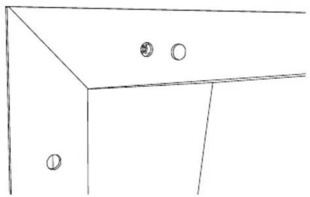
natural_image
Simple line drawing of a cabinet or cabinet with two circular fixtures on one side (no text or symbols)3.4 - AUSBAU DES LAUTSPRECHERS
3.4.1 - DEN LAUTSPRECHER VOM RAHMEN ABSCHRAUBEN
natural_image
Simple line drawing of a cabinet or cabinet with two circular components on top (no text or symbols)3.4.2 - DIE AUDIOKABEL VOM LAUTSPRECHER ABKLEMMEN
natural_image
Technical line drawing of a wooden cabinet with three circular cutouts and two empty panels (no text or symbols)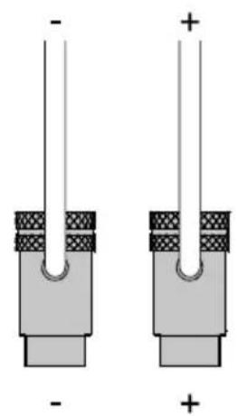
natural_image
Two identical electronic component diagrams with polarity markings, no text or symbols present
natural_image
Technical line drawing of a mechanical bracket assembly with mounting holes and a central fastener (no text or symbols)natural_image
Pure mechanical diagram showing a rotating shaft and housing with curved arrows indicating motion (no text or symbols)natural_image
Technical line drawings of two mechanical lifting or mounting mechanisms with pulleys and bolts (no text or symbols)
| ARENA 30 ARENA | 20 ARENA 10 ARENA | S15 | ||
| Speaker type 4 way | 3.5 way 3.0 way | Array Balanced Sub-Woofer | ||
| Low frequency transducer | 2 x 8 in 2 x 8 in 4 x 6.5 in 4 x 6.5 in | |||
| Mid/High frequency transducer | 2 x 6.25 in 38 mm Dome Tw + 19 mm Super Tw | 1 x 6.25 in + 19 mm Dome Tw | 1 x 6.25 in + 19 mm Tw | - |
| Maximum recommended power | 600 W 400 W 400 W 400 W | |||
| Frequency response (-6dB on-axis) | 40 Hz 32,200.0 Hz | 55 Hz 31,500.0 Hz | 36 Hz 31,585.0 Hz | 31.5 Hz 180 Hz |
| Frequency Response (-3dB on-axis) | 50 Hz 26,200.0 Hz | 60 Hz 24,710.0 Hz | 40 Hz 33,580.0 Hz | 29 Hz 180 Hz |
| Max SPL 1 Meter 120,0 dB 117,0 dB | 111.0 dB 117,0 dB | |||
| Sensitivity 2.83 Vrms@1m | 94.0 dB | 92.0 dB | 88.5 dB | 91.0 dB |
| Nominal impedance | 4 Ω | 4 Ω | 4 Ω | 4 Ω |
| Minimal impedance | 2.9 Ω 3.6 Ω | 3.5 Ω | 3.5 Ω | |
| Crossover frequencies | 200 Hz / 2k Hz / 10k Hz | 160 Hz / 220 Hz / 3100 Hz | 250 Hz / 2100 Hz | 160 Hz / 220 Hz / 3100 Hz |
| Enclosure type | Closed Box | Closed Box | Closed Box | Patent Pending Acoustical Load |
| Mounting Depth | 162 mm - 6.4 in | 144 mm - 5.7 in | 150 mm - 5.9 in | 202 mm - 7.9 in |
| Weight | 58.7 kg - 129.4 lb | 47.2 kg - 104.1 lb | 25 kg - 55.1 lb | 38.7 kg - 85.3 lb |
| Depth | 167 mm - 6.6 in | 150 mm - 5.9 in | 150 mm - 5.9 in | 208 mm - 8.1 in |
| Width | 321 mm - 12.6 in | 321 mm - 12.6 in | 590 mm - 23.2 in | 432 mm - 17 in |
| Height | 1,774 mm - 69.8 in | 1,577 mm - 62.1 in | 590 mm - 23.2 in | 947 mm - 37.2 in |
СОДЕРЖАНИЕ
natural_image
Three sequential diagrams showing human figures interacting with a vertical structure and a platform, illustrating mechanical or structural changes (no text or symbols present)3.3 - МОНТАЖ
natural_image
Technical line drawing of a two-panel door frame structure (no text or symbols)natural_image
Pure architectural floor plan lines without any text, numbers, or symbols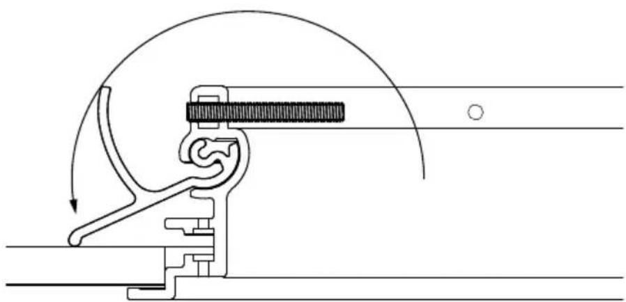
natural_image
Mechanical assembly diagram showing a lever mechanism with motion arrows (no text or labels)
natural_image
Pure technical diagram of a mechanical component inside a rectangular frame, without any text, numbers, or symbols.
natural_image
Technical line drawing of a mechanical clamp or tool assembly (no text or symbols)natural_image
Technical line drawing of a two-panel cabinet with circular cutouts and mounting flanges (no text or symbols)natural_image
Simple line drawing of a cabinet or cabinet with two circular fixtures and a handle (no text or symbols)
natural_image
Simple line drawing of a cabinet or cabinet with two circular fixtures on one side (no text or symbols)natural_image
Simple line drawing of a cabinet or cabinet with three circular components on one side (no text or symbols)3.4.2 - ОТСОЕДИНИТЕ АУДИОКАБЕЛИ ОТ АКУСТИЧЕСКОЙ СИСТЕМЫ
natural_image
Technical line drawing of a wall-mounted device with three circular components mounted on a frame, shown in two orthogonal views (no text or symbols)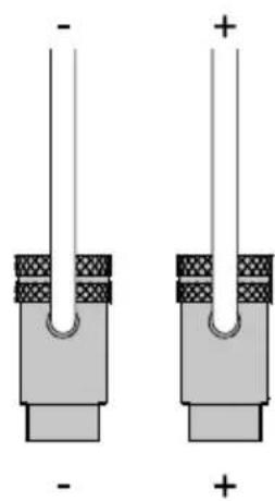
natural_image
Two identical mechanical or electrical component diagrams with no visible text, numbers, or symbols.Py

natural_image
Technical line drawing of a mechanical assembly with mounting bracket and circular components (no text or symbols)4.3.4 – ОТРЕГУЛИРУЙТЕ ВЫСОТУ И УГОЛ НАКЛОНА ДИФФУЗОРА, ЗАТЕМ ЗАТЯНИТЕ ВИНТОМ
natural_image
Pure mechanical diagram showing a rotating shaft and housing with curved arrows indicating motion (no text or symbols)natural_image
Technical line drawings of two mechanical lifting or mounting mechanisms with pulleys and bolts (no text or symbols)
World copyright reserved
Sonus faber reserves the right to change any technical and/or aesthetical feature of its products at any time without any previous notice.





- SOMMARIO
- - MONTAGGIO
- - SPINGERE LE ALETTE METALLICHE A CONTATTO CON IL MURO INTERNO
- - INSERIRE IL DIFFUSORE ACUSTICO NELLA CORNICE
- - AVVITARE IL DIFFUSORE ACUSTICO ALLA CORNICE CHIUDERE CON I COPRI VITI
- - SCOLLEGARE I CAVI AUDIO DAL DIFFUSORE
- - SVITARE LA CORNICE E ALLINEARE LE ALETTE METALLICHE RIMUOVERE LA CORNICE DAL MURO
- CONTENTS
- GENERAL INFORMATION
- - INFORMATION FOR THE USER
- - WARRANTY AND AFTER SALES SUPPORT
- SAFETY INFORMATION
- INSTALLATION (Arena 30 - Arena 20 - Arena S15)
- - PACKAGING CONTENTS
- - UNPACKING
- - INSERT THE FRAME IN THE DRILLED HOLE
- - PUSH THE METALLIC FINS INTO CONTACT WITH THE INTERNAL WALL
- - SCREW THE FRAME
- - INSERT THE LOUDSPEAKER IN THE FRAME
- - SCREW THE LOUDSPEAKER TO THE FRAME CLOSE WITH THE SCREW COVERS
- - UNSCREW THE FRAME AND ALIGN THE METAL FINS REMOVE THE FRAME FROM THE WALL
- INSTALLATION (Arena 10)
- - PACKAGING CONTENTS
- - UNPACKING
- MAINTENANCE AND CLEANING
- TECHNICAL SPECIFICATIONS
- SOMMAIRE
- - MONTAGE
- - POUSSER LES AILETTES MÉTALLIQUES EN CONTACT AVEC LA PAROI INTÉRIEURE
- - INSÉRER L'ENCEINTE ACOUSTIQUE DANS LE CADRE
- - DÉVISSER LE CADRE ET ALIGNER LES AILETTES MÉTALLIQUES RETIRER LE CADRE DU MUR
- INHALTSVERZEICHNIS
- - DEN LAUTSPRECHER IN DEN RAHMEN EINSETZEN
- СОДЕРЖАНИЕ
Brand : Sonus Faber
Model : Arena 10
Category : Loudspeaker