
Palladio PW-562 - Loudspeaker Sonus Faber - Free user manual and instructions
Find the device manual for free Palladio PW-562 Sonus Faber in PDF.


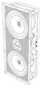
| Product Type | In-wall/ceiling speaker |
| Brand | Sonus Faber |
| Model | Palladio PW-562 |
| Category | Speaker |
| Nominal Impedance | 4 ohms |
| Sensitivity | 92 dB SPL |
| Recommended Amplifier Power (per channel) | 40 W to 125 W RMS depending on listening distance |
| Power Supply | Passive (powered by external amplifier) |
| Main Functions | Audio reproduction, flush-mount installation, removable and paintable magnetic grille |
| Maintenance and Cleaning | Clean with a soft dry cloth; paintable grille |
| Safety | Avoid prolonged exposure to high volume; respect polarity; do not connect in parallel on 100 V line |
| Spare Parts and Repairability | Magnetic grille, protective cover, pre-mount kit (optional); assistance via dealer or Sonus Faber after-sales service |
| General Information | Warranty against manufacturing defects; online registration recommended; keep original packaging |
| Package Contents | Speaker, magnetic grille, cutout template, plastic protective cover |
| Installation | Wall/ceiling cutout; screw fixing; requires external amplifier |
| Optional Accessories | Square magnetic grille (for ceiling), pre-mount kit |
| Amplifier Compatibility | Stereo or home cinema amplifiers with 4 ohms minimum impedance |
Frequently Asked Questions - Palladio PW-562 Sonus Faber
User questions about Palladio PW-562 Sonus Faber
0 question about this device. Answer the ones you know or ask your own.
Ask a new question about this device
Download the instructions for your Loudspeaker in PDF format for free! Find your manual Palladio PW-562 - Sonus Faber and take your electronic device back in hand. On this page are published all the documents necessary for the use of your device. Palladio PW-562 by Sonus Faber.
USER MANUAL Palladio PW-562 Sonus Faber
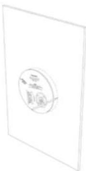
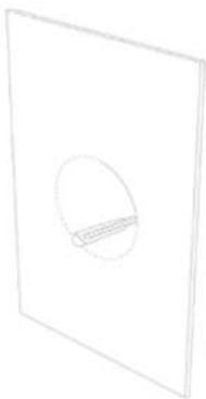
3.3 - TAGLIARE LUNGO IL PERIMETRO SEGNATO
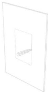
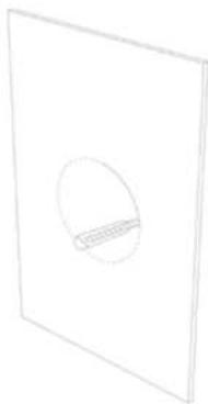
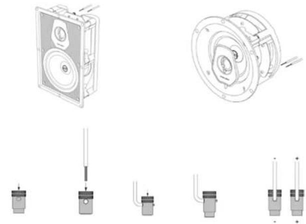
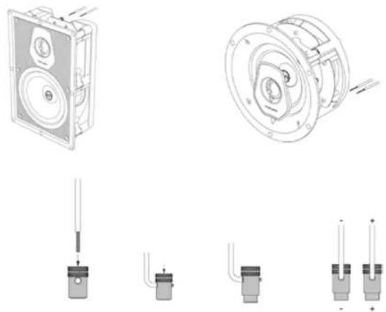
3.4 - COLLEGARE I CAVI AUDIO AL DIFFUSORE

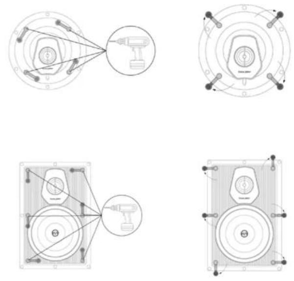
3.6 - FISSARE IL DIFFUSORE ALLA PARETE
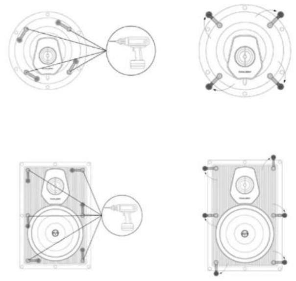
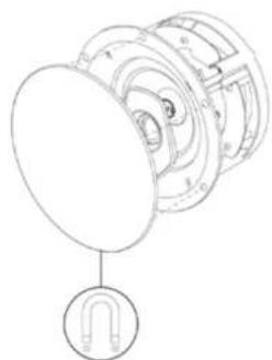
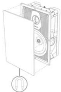
3.8 - APPLICARE LA GRIGLIA MAGNETICA


1.1 Information for the user 13
1.2 Warranty and after sales support 14
- Safety information 14
2.1 Recommendations for choosing the audio amplifier 15
- Installation 15
3.1 Packaging contents 15
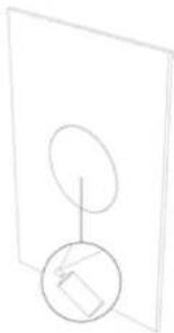
3.2 Mark the area to be cut on the wall using the template supplied 16
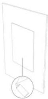
3.3 Cut along the perimeter marked 16
3.4 Connect the audio cables to the speaker 17
3.5 Introduce the speaker into the hole made 17
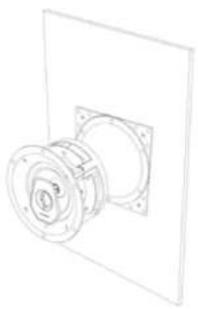
3.6 Fix the speaker to the wall 18
3.7 Positioning the logo (PL-563 E PC-563P models only) 19
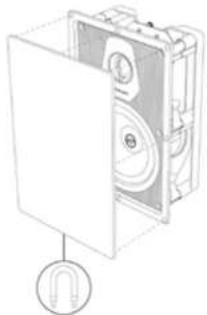
3.8 Apply the magnetic grid 20
- Optional accessories 21
4.1 Square magnetic grid (for In-Ceiling models) 21
4.2 Support bracket and safety cables 21
-
Removing the speaker 22
-
Technical specifications 46 / 47
-
Positioning of the speakers 48
7.1 System configurations 48
1. GENERAL INFORMATION
1.1 INFORMATION FOR USERS
Dear Customer,
We would like to thank and congratulate you on choosing Palladio Level 5 for your audio/audio-video system.
Since we want you to obtain the best possible listening result in full safety, please read this instruction manual carefully before installation.
Should you have any doubts or enquiries, please contact your sales point's technical staff, the official Sonus faber distributor in your country, or Sonus faber directly by writing to customerservice@sonusfaber.com.
Finally, we highly suggest registering online at www.sonusfaber.com in order to keep up to date on all the latest news, initiatives and promotions offered by Sonus faber.
Enjoy your music!
1.2 WARRANTY AND AFTER-SALES ASSISTANCE
Palladio Level 5 loudspeakers are designed and manufactured according to the highest quality standards.
Should, however, a fault or a malfunction occur, the loudspeakers are covered by warranty, in compliance with the regulations in force in the country where the loudspeakers were purchased. In such cases, please contact the dealer from whom you purchased your loudspeakers, or the official Sonus faber distributor for your country; the contact information for all the distributors can be found on our website:
- https://www.sonusfaber.com/distributori-store/
- https://www.sonusfaber.com/en/distributors-stores/
The following should also be kept in mind for your convenience:
• The warranty on the loudspeakers covers any manufacturing defects;
- Keep the receipt as proof of purchase to show to the retailer if necessary;
- Keep the original packaging of the loudspeakers so that they can be transported without undergoing damage, if they need to be shipped to an authorised service centre;
- The loudspeakers must be accompanied by a description of the malfunction or defect encountered.
The product's warranty will be void under the following conditions:
- If the product has been disassembled or modified by persons other than a Sonus faber authorised service centre;
If the product has been used in a manner that is not consistent with the indications contained within this manual.
2. SAFETY INFORMATION
This instruction manual must be read carefully and kept in an accessible location for any needs that may arise.
- Make sure that in-wall/in-ceiling fixing is suitably stable.
- Previously check that the capacity of the mounting surface is sufficient to support the weight of the loudspeaker/s.
- Avoid staying in close proximity to the loudspeakers while the audio system is operating at high volume. This can cause permanent damage to your hearing. Children must be kept at a safety distance of least 50 cm from the loudspeaker.
- The speakers generate an electromagnetic field that is harmless to humans and pets, but can compromise the proper functionality of electronic equipment, such as CRT monitors or TVs, when placed in close proximity. If this occurs, increase the equipment's distance from the loudspeakers.
- The technology underlying the speakers' functionality is based on the principles of electromagnetism, and the user should therefore avoid operating equipment that generates strong electromagnetic fields, as these could affect the loudspeaker's proper functionality.
- Do not connect the loudspeakers parallel to each other or directly to a constant voltage sound distribution system (100 V, 70.7 V or similar). This could result in a serious system overload, with possible damage to the loudspeaker and/or the amplifier.
- Do not place audio cables and electrical power cables in close proximity to one another. An electromagnetic field is present in the vicinity of the power cables, which can cause an unpleasant humming noise. If this should occur, move the audio cables and electrical power cables away from each other.
- The connections must be made with the equipment turned off. Pay attention to the polarities of the terminals during connection.
2.1 - RECOMMENDATIONS FOR CHOOSING THE AUDIO AMPLIFIER
The output power data required by amplifier in average conditions of use, depends on the features of the loudspeaker system (nominal impedance and sensitivity) and listening conditions (average acoustic level and listening point). In the case of loudspeaker with nominal impedance of 4 ohm and sensitivity of 92 dB SPL, the following table is given
| LISTENING DISTANCE | AMPLIFIER OUTPUT POWER (MINIMUM, PER CHANNEL) * | CORRESPONDING INPUT POWER (PER CHANNEL) * |
| 2 m 40 Wrms 0.8 W | ||
| 2.5 m | 63 Wrms | 1,3 W |
| 3 m 90 Wrms 1.8 W | ||
| 3,5 m | 125 Wrms | 2,3 W |
| * for an average volume level at a listening distance equal to 82 dBSPL | ||
Audio programs with higher peak factors require even higher amplification powers.
As it can be seen, the cost in terms of amplification is not so much the maintenance of the listening level as the management of the very short moments in which the musical signal has extraordinarily high levels.

Loudspeaker systems for household use. They must not be used for high volume and continuous sound distribution, as, for example discotheque or sound reinforcement. In this type of application, the powers in question are incompatible with correct operation of the loudspeaker system and can lead to irreversible faults and, in some cases, the start of a fire.
3. INSTALLATION
3.1 PACKAGING CONTENTS
- Speaker
- Magnetic grid
- Template for the hole
• Plastic protective cover
Every optional accessory, which can be purchased separately, is illustrated in Chapter 4.

The packaging materials can cause pollution. These materials must not be disposed of as domestic waste, and must be brought to a waste collection and recycling centre.

Do not leave the packaging materials within the reach of children! They could pose a risk of poisoning or suffocation if ingested.
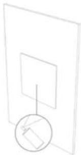
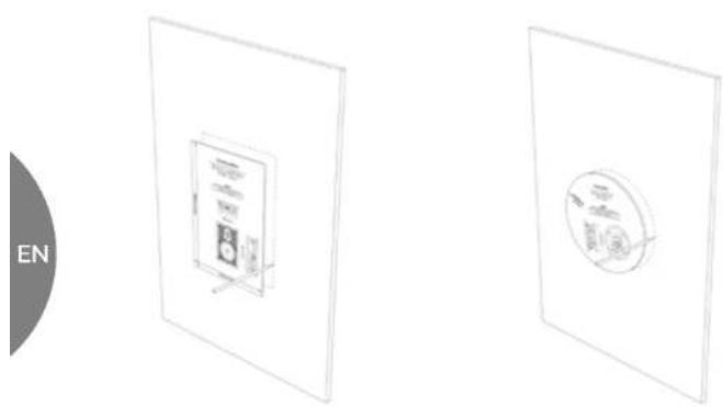
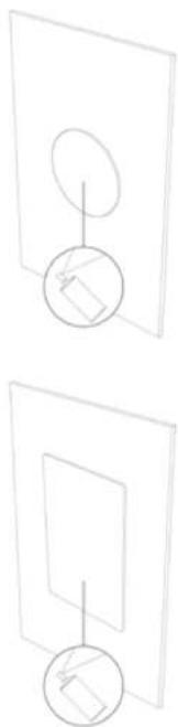
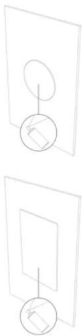
3.2 MARK THE AREA TO BE CUT ON THE WALL USING THE TEMPLATE SUPPLIED

Previously, make sure that the cutting area is between the two uprights. For correct operation of the fixing system, maintain a distance of at least 4 cm between the lateral edge of the hole and the nearest upright.
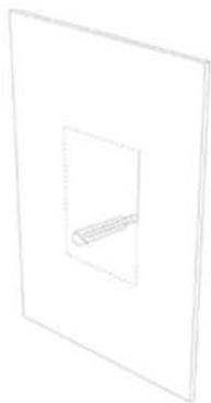
3.3 CUT ALONG THE PERIMETER MARKED
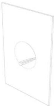
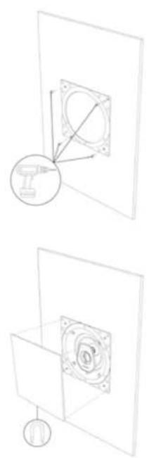
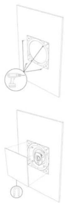
Pay attention to the polarities of the terminals during connection. The connections must be made with the equipment turned off!
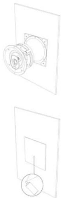
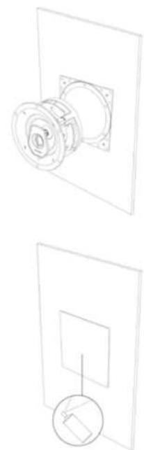
3.5 INTRODUCE THE SPEAKER INTO THE HOLE MADE
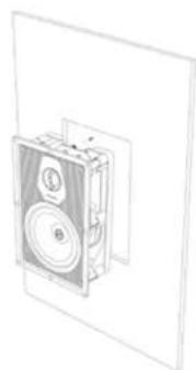
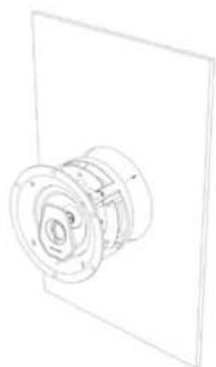
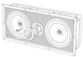
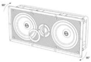
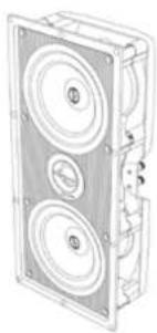
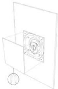
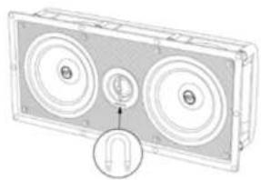
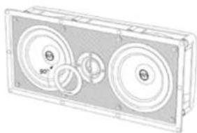
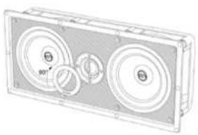
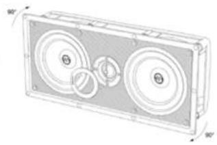
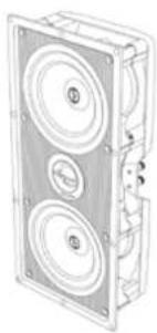
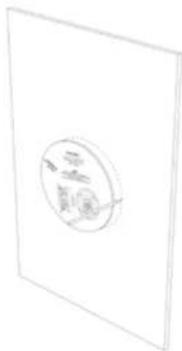
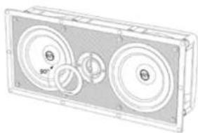
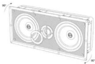
The PL-563 and PC-563P models are set-up to be installed both horizontally and vertically. The ring with the Sonus faber logo around the tweeter, is applied magnetically. To position it according to use desired, approach any metal object to it to remove it and reposition it.

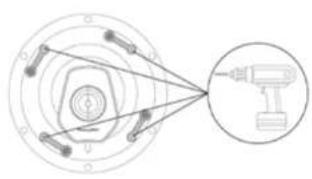
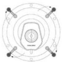
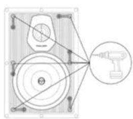
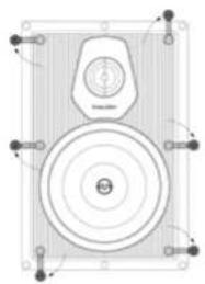
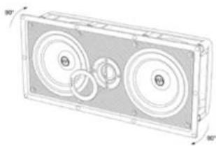
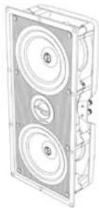

Tighten the locking screws fully home without force, to prevent damage to the locking system.
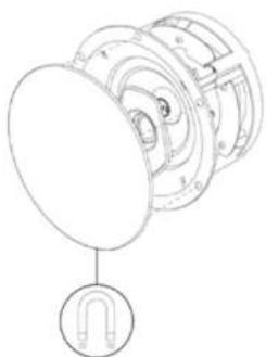
3.8 APPLY THE MAGNETIC GRID
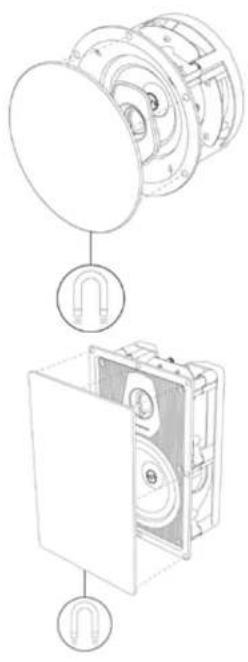
4. OPTIONAL ACCESSORIES
4.1 SQUARE MAGNETIC GRID (FOR IN-CEILING MODELS)

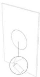
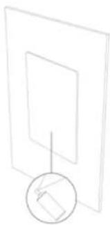
Before introducing the speaker into the hole, screw the relevant support to the wall. The grid can be painted as desired. Painting is recommended outdoors and away from the speaker.
4.2 PRE-ASSEMBLY KIT (NEW CONSTRUCTION)
The pre-assembly kit is available if the Palladio Level 5 collection speakers must be installed in a new construction. For additional information, consult the relevant user manual contained in the packaging of the same.

The grid can be painted as desired.
Painting is recommended outdoors and away from the speaker.
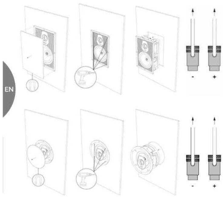
- REMOVING THE SPEAKER
FRANÇAIS
| Loosen the screws fully home to guarantee complete closure of the locking system and easy speaker removal. | |
| Perform the operation with the appliances off! |
TABLE DES MATIÈRES

3.3 DECOUPER LE LONG DU PERIMETRE MARQUE
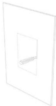
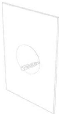
3.4 CONNECTER LES CABLES AUDIO AU HAUT PARLEUR
3.6 FIXER L'ENCEINTE AU MUR
FR

3.4 DIE AUDIO-KABEL AM LAUTSPRECHER ANSCHLIESSEN


3.6 DEN LAUTSPRFECHER AN DER WAND BEFESTIGEN

4. OPTIONALES ZUBEHÖR
4.1 QUADRATISCHES MAGNETISCHES GITTER (NUR FÜR MODELLE IN-CEILING)

| 6. TECHNICAL SPECIFICATIONS | PC-562 PC-562P | PC-582 PC-563P PL-563 | PW-562 PS-G101 | ||||
| Loudspeaker system | 2 way in-ceiling system. Infinite baffle. | 2 way in-ceiling system. Infinite baffle. | 2 way in-ceiling system. Infinite baffle. | 2 way point in-ceiling system. Infinite baffle. | 2 way left/right/center in-wall system. Infinite baffle. | 2 way in-wall system. Infinite baffle. | In-wall passive subwoofer. Infinite baffle. |
| Tweeter DADTM driver | 29 mm1.1 in | 29 mm1.1 in | 29 mm1.1 in | 29 mm1.1 in | 29 mm1.1 in | 29 mm1.1 in | - |
| Woofer / Midwoofer | 165 mm6.5 in | 165 mm6.5 in | 200 mm8 in | 2 x 165 mm2 x 6.5 in | 2 x 165 mm2 x 6.5 in | 165 mm6.5 in | 250 mm10 in |
| Crossover frequency Paracross TopologyTM | 3,000 Hz 3,000 Hz | 3,000 Hz 1,650 Hz 1,650 Hz | 3,000 Hz - | ||||
| Frequency response | 50 - 25,000 Hz | 50 - 25,000 Hz | 45 - 25,000 Hz | 45 - 25,000 Hz | 50 - 25,000 Hz | 50 - 25,000 Hz | 25 - 1,000 Hz (**) |
| Sensitivity (2.83v/1m) | 90 dBSPL | 90 dBSPL | 90 dBSPL | 92 dBSPL | 92 dBSPL | 88 dBSPL | 90 dBSPL |
| Nominal impedance | 4 Ω | 4 Ω | 4 Ω | 4 Ω | 4 Ω | 4 Ω | 4 Ω |
| Coverage Angle (1 kHz, @-6 dB) | ±60° H - ±60° V | ±60° H - ±60° V | ±60° H - ±60° V | ±45° H - ±45° V | ±45° H - ±60° V | ±60° H - ±60° V | - |
| Suggested amplifier power output (*) | 40 - 200W without clipping | 40 - 200W without clipping | 40 - 200W without clipping | 40 - 250W without clipping | 40 - 250W without clipping | 40 - 200W without clipping | 200 - 800W |
| Frame outer | ∅ 234 mm9.2 in | ∅ 265.2 mm10.4 in | ∅ 283 mm11.1 in | 460 x 386 mm18.1 x 15.1 in | 471 x 216 mm18.5 x 8.5 in | 216 x 323 mm8.5 x 12.7 in | 310 x 310 mm12.2 x 12.2 in |
| Cut out | ∅ 208 mm8.19 in | ∅ 244 mm9.6 in | ∅ 257 mm10.1 in | 433 x 359 mm17 x 14.1 in | 448 x 192 mm17.6 x 7.6 in | 192 x 299 mm7.6 x 11.8 in | 280 x 280 mm11 x 11 in |
| Depth behind surface | 115 mm4.52 in | 170 mm6.70 in | 139 mm5.5 in | 148 mm5.82 in | 101 mm3.4 in | 101 mm3.4 in | 98 mm3.8 in |
| Protrusion | 10 mm0.40 in | 10 mm0.40 in | 13 mm0.51 in | 13 mm0.51 in | 13 mm0.51 in | 12 mm0.47 in | 23 mm0.9 in |
| Net Weight | 3.1 Kg6.8 lb | 3.2 Kg7 lb | 3.4 Kg7.5 lb | 6.5 Kg14.3 lb | 6.3 Kg13.9 lb | 3.7 Kg8.2 lb | 5.6 Kg12.4 lb |
| Included in the box | Bezel-Free round magnetic grille | Bezel-Free round magnetic grille | Bezel-Free round magnetic grille | Bezel-Free square magnetic grille | Bezel-Free square magnetic grille | Bezel-Free square magnetic grille | Bezel-Free square magnetic grille |
| Additional fittings | Bezel-Free square magnetic grille | Bezel-Free square magnetic grille | Bezel-Free square magnetic grille | - | - | - | - |
| Pre-mount kit | Pre-mount kit | Pre-mount kit | - | - | - | - |
* See instruction's manual for more information.
** Unfiltered & unequalized. External filtering required.
- Recommended for clear reproduction of the bass sounds
- Extreme configuration for maximum acoustic output
- Recommended for clear reproduction of the bass sounds (additional subwoofer)
- Extreme configuration for maximum acoustic output (additional subwoofer)
NOTE
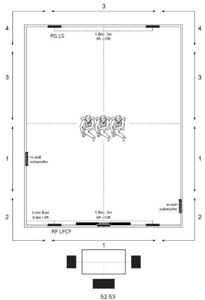
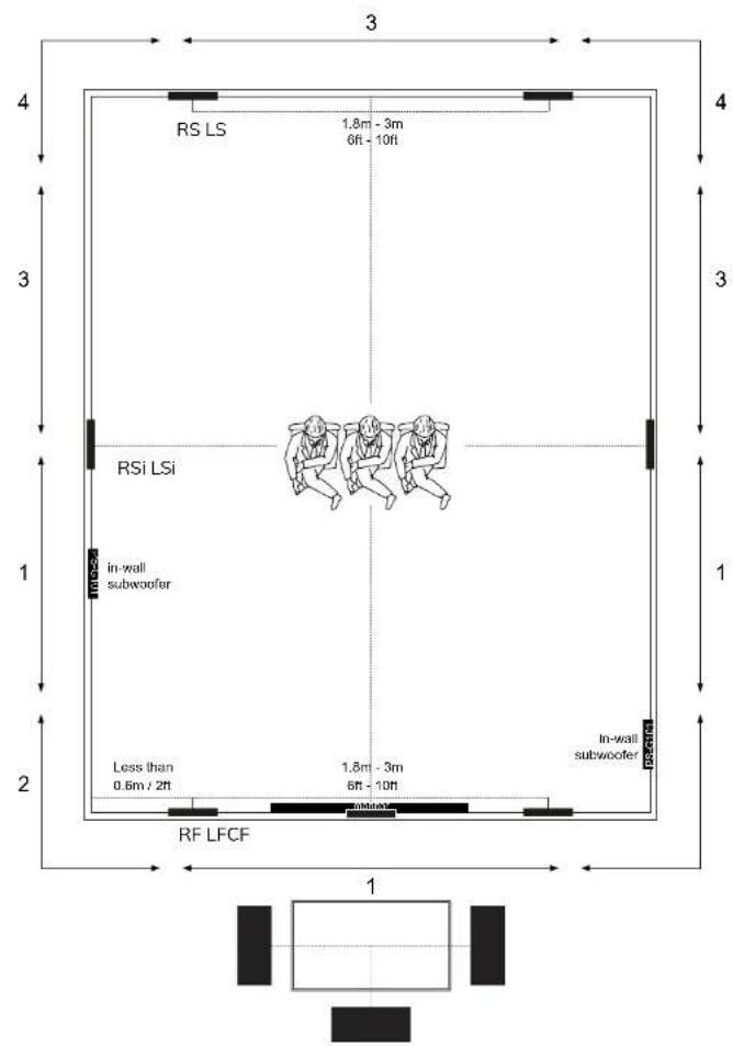
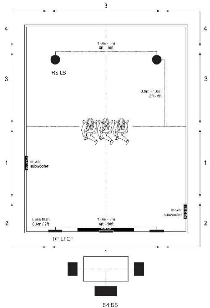
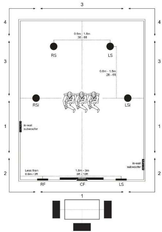
If two subwoofer units are used, it is greatly recommended to install one on the left and one on the right of the listening area. Do not position the subwoofers symmetrically to each other with respect to the main listening point.
7. POSITIONNEMENT DES ENCEINTES
7.1 CONFIGURATIONS DU SYSTEME
LEGENDE - POSITIONNEMENT DE CAISSON(S) DE BASSES
OPTION 3: 5.1 IN-WALL
OPTION 4: 7.1 IN-WALL
OPTION 5:
5.1 IN-CEILING + IN-WALL
OPTION 6: 7.1 IN-CEILING + IN-WALL

© COPYRIGHT 2019
World copyright reserved





- 3.3 - TAGLIARE LUNGO IL PERIMETRO SEGNATO
- 3.8 - APPLICARE LA GRIGLIA MAGNETICA
- GENERAL INFORMATION
- 1.2 WARRANTY AND AFTER-SALES ASSISTANCE
- SAFETY INFORMATION
- 2.1 - RECOMMENDATIONS FOR CHOOSING THE AUDIO AMPLIFIER
- INSTALLATION
- 3.1 PACKAGING CONTENTS
- OPTIONAL ACCESSORIES
- 4.2 PRE-ASSEMBLY KIT (NEW CONSTRUCTION)
- FRANÇAIS
- TABLE DES MATIÈRES
- 3.3 DECOUPER LE LONG DU PERIMETRE MARQUE
- OPTIONALES ZUBEHÖR
- POSITIONNEMENT DES ENCEINTES
Brand : Sonus Faber
Model : Palladio PW-562
Category : Loudspeaker