VIKING 2450 ADV - Welding machine LINCOLN ELECTRIC - Free user manual and instructions
Find the device manual for free VIKING 2450 ADV LINCOLN ELECTRIC in PDF.



User questions about VIKING 2450 ADV LINCOLN ELECTRIC
0 question about this device. Answer the ones you know or ask your own.
Ask a new question about this device
Download the instructions for your Welding machine in PDF format for free! Find your manual VIKING 2450 ADV - LINCOLN ELECTRIC and take your electronic device back in hand. On this page are published all the documents necessary for the use of your device. VIKING 2450 ADV by LINCOLN ELECTRIC.
USER MANUAL VIKING 2450 ADV LINCOLN ELECTRIC
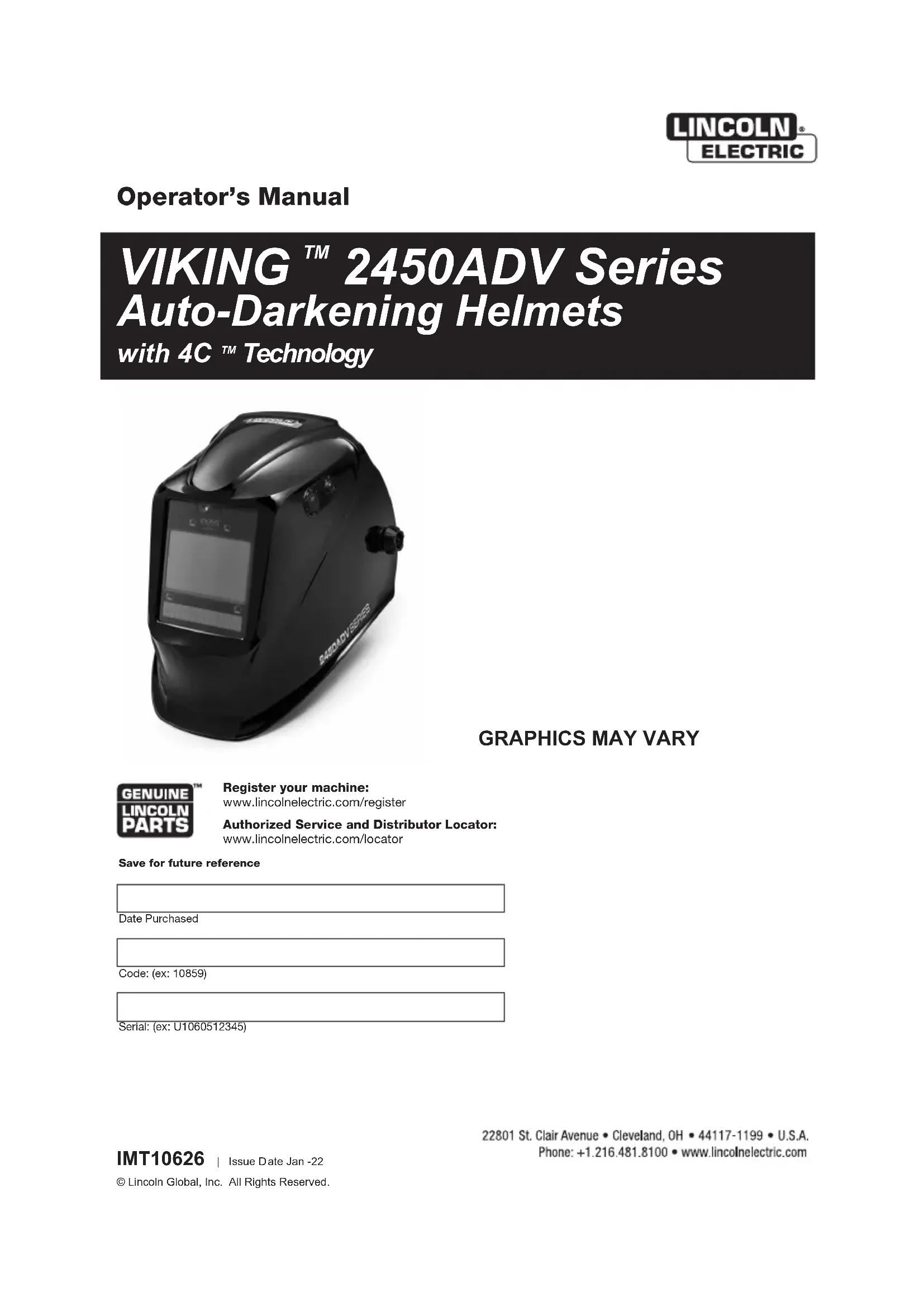
with 4C ^TM Technology
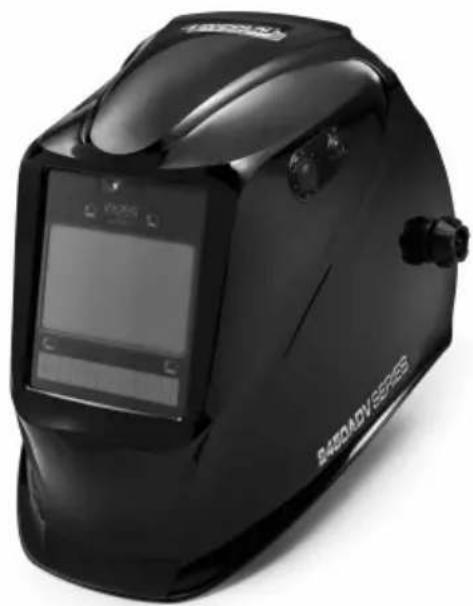
natural_image
Black welding helmet with digital display and 'R450ADV SERIES' branding (no readable text beyond label)GRAPHICS MAY VARY

Register your machine:
www.lincolnelectric.com/register
Authorized Service and Distributor Locator:
www.lincolnelectric.com/locator
Save for future reference
Date Purchased
Code: (ex: 10859)
Serial: (ex: U1060512345)
THANK YOU FOR SELECTING A QUALITY PRODUCT BY LINCOLNELECTRIC.
PLEASE EXAMINE CARTON AND EQUIPMENT FOR DAMAGE IMMEDIATELY
When this equipment is shipped, title passes to the purchaser upon receipt by the carrier. Consequently, claims for material damaged in shipment must be made by the purchaser against the transportation company at the time the shipment is received.
SAFETY DEPENDS ON YOU
Lincoln arc welding and cutting equipment is designed and built with safety in mind. However, your overall safety can be increased by proper installation ... and thoughtful operation on your part. DO NOT INSTALL, OPERATE OR REPAIR THIS EQUIPMENT WITHOUT READING THIS MANUAL AND THE SAFETY PRECAUTIONS CONTAINED THROUGHOUT. And, most importantly, think before you act and be careful.

WARNING
This statement appears where the information must be followed exactly to avoid serious personal injury or loss of life.

CAUTION
This statement appears where the information must be followed to avoid minor personal injury or damage to this equipment.
KEEP YOUR HEAD OUT OF THE FUMES.
DON'T get too close to the arc. Use corrective lenses if necessary to stay a reasonable distance away from the arc.
READ and obey the Safety Data Sheet (SDS) and the warning label that appears on all containers of welding materials.
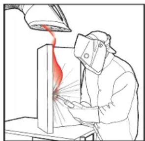
USE ENOUGH VENTILATION or exhaust at the arc, or both, to keep the fumes and gases from your breathing zone and the general area.
natural_image
Illustration of a person in protective gear using a tool to spray or spray from a lamp (no text or symbols present)IN A LARGE ROOM OR OUTDOORS, natural ventilation may be adequate if you keep your head out of the fumes (See below).
USE NATURAL DRAFTS or fans to keep the fumes away from your face.
If you de velop unusual symptoms, see your supervisor. Perhaps the welding atmosphere and ventilation system should be checked.
natural_image
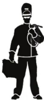
Silhouette of a person wearing a welding helmet and holding a tool, no text or symbols presentWEAR CORRECT EYE, EAR & BODY PROTECTION
PROTECT your eyes and face with welding helmet properly fitted and with proper grade of filter plate (See ANSI Z49.1).
PROTECT your body from welding spatter and arc flash with protective clothing including woolen clothing, flame-proof apron and gloves, leather leggings, and high boots.
PROTECT others from splatter, flash, and glare with protective screens or barriers.
IN SOME AREAS, protection from noise may be appropriate.
BE SURE protective equipment is in good condition.
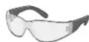
Also, wear safety glasses in work area AT ALL TIMES.
SPECIAL SITUATIONS
DO NOT WELD OR CUT containers or materials which previously had been in contact with hazardous substances unless they are properly cleaned. This is extremely dangerous.
DO NOT WELD OR CUT painted or plated parts unless special precautions with ventilation have been taken. They can release highly toxic fumes or gases.
Additional precautionary measures
PROTECT compressed gas cylinders from excessive heat, mechanical shocks, and arcs; fasten cylinders so they cannot fall.
BE SURE cylinders are never grounded or part of an electrical circuit.
REMOVE all potential fire hazards from welding area.
ALWAYS HAVE FIRE FIGHTING EQUIPMENT READY FOR IMMEDIATE USE AND KNOW HOW TO USE IT.

SECTION A: WARNINGS

CALIFORNIA PROPOSITION 65 WARNINGS

WARNING: Breathing diesel engine exhaust exposes you to chemicals known to the State of California to cause cancer and birth defects, or other reproductive harm.
- Always start and operate the engine in a well-ventilated area.
- If in an exposed area, vent the exhaust to the outside.
- Do not modify or tamper with the exhaust system.
- Do not idle the engine except as necessary.
For more information go to www.P65 warnings.ca.gov/diesel
WARNING: This product, when used for welding or cutting, produces fumes or gases which contain chemicals known to the State of California to cause birth defects and, in some cases, cancer. (California Health & Safety Code § 25249.5 et seq.)

WARNING: Cancer and Reproductive Harm www.P65warnings.ca.gov
ARC WELDING CAN BE HAZARDOUS. PROTECT YOURSELF AND OTHERS FROM POSSIBLE SERIOUS INJURY OR DEATH. KEEP CHILDREN AWAY. PACEMAKER WEARERS SHOULD CONSULT WITH THEIR DOCTOR BEFORE OPERATING.
Read and understand the following safety highlights. For additional safety information, it is strongly recommended that you purchase a copy of "Safety in Welding & Cutting - ANSI Standard Z49.1" from the American Welding Society, P.O. Box 351040, Miami, Florida 33135 or CSA Standard W117.2. A Free copy of "Arc Welding Safety" booklet E205 is available from the Lincoln Electric Company, 22801 St. Clair Avenue, Cleveland, Ohio 44117-1199.
BE SURE THAT ALL INSTALLATION, OPERATION, MAINTENANCE AND REPAIR PROCEDURES ARE PERFORMED ONLY BY QUALIFIED INDIVIDUALS.

FOR ENGINE POWERED EQUIPMENT.
1.a. Turn the engine off before troubleshooting and maintenance work unless the maintenance work requires it to be running.
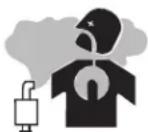
1.b. Operate engines in open, well-ventilated areas or vent the engine exhaust fumes outdoors.
1.c. Do not add the fuel near an open flame welding arc or when the engine is running. Stop the engine and allow it to cool before refueling to prevent spilled fuel from vaporizing on contact

with hot engine parts and igniting. Do not spill fuel when filling tank. If fuel is spilled, wipe it up and do not start engine until fumes have been eliminated.
1.d. Keep all equipment safety guards, covers and devices in position and in good repair. Keep hands, hair, clothing and tools away from V-belts, gears, fans and all other moving parts when starting, operating or repairing equipment.

1.e. In some cases it may be necessary to remove safety guards to perform required maintenance. Remove guards only when necessary and replace them when the maintenance requiring their removal is complete. Always use the greatest care when working near moving parts.
1.f. Do not put your hands near the engine fan. Do not attempt to override the governor or idler by pushing on the throttle control rods while the engine is running.
1.g. To prevent accidentally starting gasoline engines while turning the engine or welding generator during maintenance work, disconnect the spark plug wires, distributor cap or magneto wire as appropriate.
1.h. To avoid scalding, do not remove the radiator pressure cap when the engine is hot.
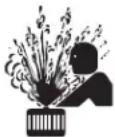
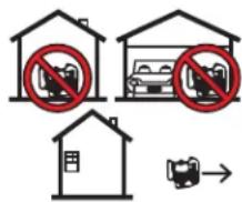
1.i. Using a generator indoors CAN KILL YOU IN MINUTES.
1.j. Generator exhaust contains carbon monoxide. This is a poison you cannot see or smell.
1.k. NEVER use inside a home or garage, EVEN IF doors and windows are open.
1.I. Only use OUTSIDE and far away from windows, doors and vents.
1.m. Avoid other generator hazards. READ MANUAL BEFORE USE.
text_image
Diagram showing three scenarios of a vehicle with no parking, including a house and a car, with a rightward arrow indicating direction.
ELECTRIC AND MAGNETIC FIELDS MAY BE DANGEROUS
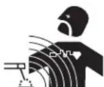
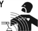
2.a. Electric current flowing through any conductor causes localized Electric and Magnetic Fields (EMF). Welding current creates EMF fields around welding cables and welding machines
2.b. EMF fields may interfere with some pacemakers, and welders having a pacemaker should consult their physician before welding.
2.c. Exposure to EMF fields in welding may have other health effects which are now not known.
2.d. All welders should use the following procedures in order to minimize exposure to EMF fields from the welding circuit:
2.d.1. Route the electrode and work cables together - Secure them with tape when possible.
2.d.2. Never coil the electrode lead around your body.
2.d.3. Do not place your body between the electrode and work cables. If the electrode cable is on your right side, the work cable should also be on your right side.
2.d.4. Connect the work cable to the workpiece as close as possible to the area being welded.
2.d.5. Do not work next to welding power source.
Safety 02 of 04 - 10/08/2021

ELECTRIC SHOCK CAN KILL.
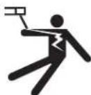
3.a. The electrode and work (or ground) circuits are electrically "hot" when the welder is on. Do
not touch these "hot" parts with your bare skin or wet clothing. Wear dry, hole-free gloves to insulate hands.
3.b. Insulate yourself from work and ground using dry insulation. Make certain the insulation is large enough to cover your full area of physical contact with work and ground.
In addition to the normal safety precautions, if welding must be performed under electrically hazardous conditions (in damp locations or while wearing wet clothing; on metal structures such as floors, gratings or scaffolds; when in cramped positions such as sitting, kneeling or lying, if there is a high risk of unavoidable or accidental contact with the workpiece or ground) use the following equipment:
- Semiautomatic DC Constant Voltage (Wire) Welder.
• DC Manual (Stick) Welder.
• AC Welder with Reduced Voltage Control.
3.c. In semiautomatic or automatic wire welding, the electrode, electrode reel, welding head, nozzle or semiautomatic welding gun are also electrically "hot".
3.d. Always be sure the work cable makes a good electrical connection with the metal being welded. The connection should be as close as possible to the area being welded.
3.e. Ground the work or metal to be welded to a good electrical (earth) ground.
3.f. Maintain the electrode holder, work clamp, welding cable and welding machine in good, safe operating condition. Replace damaged insulation.
3.g. Never dip the electrode in water for cooling.
3.h. Never simultaneously touch electrically "hot" parts of electrode holders connected to two welders because voltage between the two can be the total of the open circuit voltage of both welders.
3.i. When working above floor level, use a safety belt to protect yourself from a fall should you get a shock.
3.j. Also see It ems 6.c. and 8.

ARC RAYS CAN BURN.
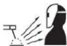
4.a. Use a shield with the proper filter and cover plates to protect your eyes from sparks and the rays of the arc when welding or observing open arc welding. Headshield and filter lens should conform to ANSI Z87. I standards.
4.b. Use suitable clothing made from durable flame-resistant material to protect your skin and that of your helpers from the arc rays.
4.c. Protect other nearby personnel with suitable, non-flammable screening and/or warn them not to watch the arc nor expose themselves to the arc rays or to hot spatter or metal.

5.a. Welding may produce fumes and gases hazardous to health. Avoid breathing these fumes and gases. When welding, keep your head out of the fume. Use enough ventilation and/or exhaust at the arc to keep fumes and gases away from the breathing zone. When welding hardfacing (see instructions on container or SDS) or on lead or cadmium plated steel and other metals or coatings which produce highly toxic fumes, keep exposure as low as possible and within applicable OSHA PEL and ACGIH TLV limits using local exhaust or mechanical ventilation unless exposure assessments indicate otherwise. In confined spaces or in some circumstances, outdoors, a respirator may also be required. Additional precautions are also required when welding on galvanized steel.
- b. The operation of welding fume control equipment is affected by various factors including proper use and positioning of the equipment, maintenance of the equipment and the specific welding procedure and application involved. Worker exposure level should be checked upon installation and periodically thereafter to be certain it is within applicable OSHA PEL and ACGIH TLV limits.
5.c. Do not weld in locations near chlorinated hydrocarbon vapors coming from degreasing, cleaning or spraying operations. The heat and rays of the arc can react with solvent vapors to form phosgene, a highly toxic gas, and other irritating products.
5.d. Shielding gases used for arc welding can displace air and cause injury or death. Always use enough ventilation, especially in confined areas, to insure breathing air is safe.
5.e. Read and understand the manufacturer's instructions for this equipment and the consumables to be used, including the Safety Data Sheet (SDS) and follow your employer's safety practices. SDS forms are available from your welding distributor or from the manufacturer.
5.f. Also see item 1.b.

WELDING AND CUTTING SPARKS CAN CAUSE FIRE OR EXPLOSION.
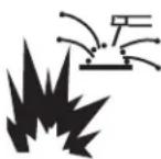
6.a. Remove fire hazards from the welding area. If this is not possible, cover them to prevent the welding sparks from starting a fire. Remember that welding sparks and hot materials from welding can easily go through small cracks and openings to adjacent areas. Avoid welding near hydraulic lines. Have a fire extinguisher readily available.
6.b. Where compressed gases are to be used at the job site, special precautions should be used to prevent hazardous situations. Refer to "Safety in Welding and Cutting" (ANSI Standard Z49.1) and the operating information for the equipment being used.
6.c. When not welding, make certain no part of the electrode circuit is touching the work or ground. Accidental contact can cause overheating and create a fire hazard.
6.d. Do not heat, cut or weld tanks, drums or containers until the proper steps have been taken to insure that such procedures will not cause flammable or toxic vapors from substances inside. They can cause an explosion even though they have been "cleaned". For information, purchase "Recommended Safe Practices for the Preparation for Welding and Cutting of Containers and Piping That Have Held Hazardous Substances", AWS F4.1 from the American Welding Society (see address above).
6.e. Vent hollow castings or containers before heating, cutting or welding. They may explode.
6.f. Sparks and spatter are thrown from the welding arc. Wear oil free protective garments such as leather gloves, heavy shirt, cuffless trousers, high shoes and a cap over your hair. Wear ear plugs when welding out of position or in confined places. Always wear safety glasses with side shields when in a welding area.
6.g. Connect the work cable to the work as close to the welding area as practical. Work cables connected to the building framework or other locations away from the welding area increase the possibility of the welding current passing through lifting chains, crane cables or other alternate circuits. This can create fire hazards or overheat lifting chains or cables until they fail.
6.h. Also see item 1.c.
6.I. Read and follow NFPA 51B "Standard for Fire Prevention During Welding, Cutting and Other Hot Work", available from NFPA, 1 Batterymarch Park, PO box 9101, Quincy, MA 022690-9101.
6.j. Do not use a welding power source for pipe thawing.

CYLINDER MAY EXPLODE IF DAMAGED.
7.a. Use only compressed gas cylinders containing the correct shielding gas for the process used and properly operating regulators designed for the gas and pressure used. All hoses, fittings, etc. should be suitable for the application and maintained in good condition.
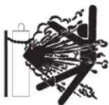
7.b. Always keep cylinders in an upright position securely chained to an undercarriage or fixed support.
7.c. Cylinders should be located:
- Away from areas where they may be struck or subjected to physical damage.
- A safe distance from arc welding or cutting operations and any other source of heat, sparks, or flame.
7.d. Never allow the electrode, electrode holder or any other electrically "hot" parts to touch a cylinder.
7.e. Keep your head and face away from the cylinder valve outlet when opening the cylinder valve.
7.f. Valve protection caps should always be in place and hand tight except when the cylinder is in use or connected for use.
7.g. Read and follow the instructions on compressed gas cylinders, associated equipment, and CGA publication P-I, "Precautions for Safe Handling of Compressed Gases in Cylinders," available from the Compressed Gas Association, 14501 George Carter Way Chantilly, VA 20151.

FOR ELECTRICALLY POWERED EQUIPMENT.

8.a. Turn off input power using the disconnect switch at the fuse box before working on the equipment.
8.b. Install equipment in accordance with the U.S. National Electrical Code, all local codes and the manufacturer's recommendations.
8.c. Ground the equipment in accordance with the U.S. National Electrical Code and the manufacturer's recommendations.
Refer to
http://www.lincolnelectric.com/safety for additional safety information.
| TABLE OF CONTENTS Page | |
| SAFETY WARNINGS – READ BEFORE USING | 1 |
| HELMET INFORMATION | 2 |
| SPECIFICATIONS | 3 |
| OPERATING INSTRUCTIONS | 4 |
| GRIND MODE OPERATION | 5 |
| LED LIGHT OPERATION | 5 |
| LED BATTERY REPLACEMENT | 6 |
| CARTRIDGE OPERATIONS/FEATURES | 7 |
| HELMET CARE AND MAINTENANCE | 10 |
| SHADE GUIDE SETTINGS | 10 |
| CARTRIDGE AND LENS REPLACEMENT | 11 |
| TROUBLESHOOTING | 12 |
| WARRANTY INFORMATION | 13 |
| REPLACEMENT PARTS | 13 |
| OPTIONAL ACCESSORIES | 14 |
SAFETY WARNINGS – READ BEFORE USING

WARNING
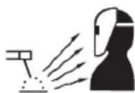
ARC Rays can injure eyes and burn skin
- Before welding, always inspect helmet and filter lens to be sure they are fitted properly, in good condition and not damaged.
- Check to see that the clear lens is clean and securely attached to the helmet.
- Always wear safety glasses or goggles under the welding helmet and protective clothing to protect your skin from radiation, burns and spatter.
- Ensure that optical radiation from other welder's arcs in the immediate area does not enter in from behind the helmet and auto-darkening filter.
Note: Auto-darkening filters in Lincoln helmets are designed to protect the user against harmful ultra-violet and infrared rays both in the dark and light states. No matter what shade the filter is set to, the UV/IR protection is always present.
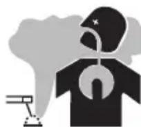
FUMES AND GASES can be dangerous to your health.
- Keep your head out of fumes.
- Use enough ventilation or exhaust at the arc or both to keep fumes and gases from your breathing zone and general area.
- When welding with electrodes which require special ventilation such as stainless or hard facing (see instructions on container or MSDS) or on lead or cadmium plated steel and other metals or coatings which produce highly toxic fumes, keep exposure as low as possible and within applicable OSHA PEL and ACGIH TLV limits using local exhaust or mechanical ventilation. In confined spaces or in some circumstances, outdoors, a respirator may be required. Additional precautions are also required when welding on galvanized steel.
Refer to http://www.lincolnelectric.com/safety for additional safety information.
HELMET INFORMATION
This Auto-Darkening Welding Helmet will automatically change from a light state (shade 3.5) to a dark state (Shade 5-13) when arc welding starts.
The filter automatically returns to a light state when the arc stops.
Match your welding application to the shade indicated on the shade chart. (See Page 10)
- Operating temperature: 14^ 131^ (-10^ 55^) .
- Do not use or open the auto-darkening filter if damaged by shock, vibration or pressure.
- Keep the sensors and solar cell clean. Clean the filter cartridge using a soapy water solution and soft cloth which should be damp but not saturated.
This Auto-Darkening Welding Helmet is designed for use with GMAW, GTAW, MMAW welding, or Plasma Arc and air carbon arc cutting.
The cartridge provides protection from harmful UV and IR radiation, in both dark and light states.
The cartridge contains four sensors to detect the light from the welding arc, resulting in the lens darkening to a selected welding shade.
- Do not use solvents or abrasive cleaning detergent.
- If cover lens is spattered or covered with dirt, it should be replaced immediately.
- Use only replacement parts specified in this manual.
- Do not use the helmet without inside and outside cover lenses properly installed.
SPECIFICATIONS
| Optical Class 1/1/1/1 | |
| LCD Viewing Area 97 x 62mm (3.82 x 2.44in.) | |
| Cartridge size 114 x 133mm (4.50 x 5.25in.) | |
| UV/IR Protection Up to Shade DIN 16 at all times | |
| Arc Sensors 4 | |
| Light State Shade DIN 3.5 | |
| Variable Welding Shades DIN 5 to 13 | |
| Shade Control | Variable shade digital control |
| Power Supply Solar cell with battery assist | |
| Low Battery Warning Red Light | |
| Grind Warning Green Light | |
| Battery | CR2450 Lithium (1 Required) |
| Power On/Off Fully automatic | |
| Light to Dark Switching Time 0.00004 sec. (1/25,000 sec.) | |
| Dark to Light Switching Time 0.1 sec. (Short) to 1.0 sec. (Long) | |
| Sensitivity Control | Variable |
| TIG Rating DC≥ 2 amps; | AC≥ 2 amps |
| Operating Temperature | 14°F ~ 131°F (-10°C ~ 55°C) |
| Storage Temperature -4° ~ 158°F (-20°C ~ 70°C) | |
| Total Weight | Black 639.5g (22.56 Oz.)Black with LED 680g (23.98 Oz.)Graphic 646.5g (22.80 Oz.)Graphic with LED 687g (24.23 Oz.) |
| Compliance | ANSI Z87.1, CSA Z94.3 |
OPERATING INSTRUCTIONS
Headgear Adjustment
text_image
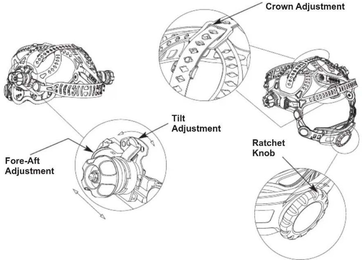
Crown Adjustment Tilt Adjustment Fore-Aft Adjustment Ratchet KnobHEAD SIZE ADJUSTMENT: HEADGEAR TIGHTNESS is adjusted by turning the Ratchet Knob to the right or left for the desired head size. This knob is located at the back of the helmet. HEADGEAR CROWN ADJUSTMENT is made by adjusting the comfort then placing the strap under the guide and snapping the pins into the holes to lock securely in place.
TILT: Tilt adjustment is located on the right side of the helmet. Loosen the right headgear tension knob and push the top end of the adjustment lever outward until the lever's Stop Tab clears the notches. Then rotate the lever forward or back to the desired tilt position. The Stop will automatically engage again when released locking the helmet into position.
FORE / AFT ADJUSTMENT: Adjusts the distance between the user's face and lens. To adjust, slide and hold the spring loaded caps upward while moving the headgear into one of four slotted locations. Once the desired distance has been achieved let go of the cap and it will return to its resting position once the adapter is secured in one of the four slots. NOTE: Make sure both sides are equally positioned for proper orientation.
natural_image
Technical line drawing of a mechanical component with two circular features and a handle (no text or symbols)In order to switch the Auto Darkening Filter from a Cutting or Welding Shade into Grind Mode first locate the silicone button on the left side of the helmet. After the button has been located press and hold it for 3 seconds. A green LED on the cartridge should blink every 3 seconds after the button is pressed to indicate you are in Grind mode. To switch back to the previous Cutting or Welding shade simply press and hold the button for 3 seconds. Grind mode is intended for grinding only not for welding.
LED LIGHT OPERATION
natural_image
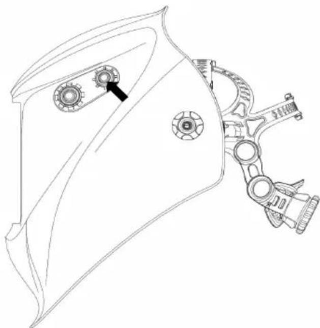
Technical line drawing of a mechanical component with gears and a handle (no text or symbols)In order to turn on the external LED, press and hold the second smaller silicone button for 3 seconds, as shown in the image. When activated the green LED light on the cartridge will turn on. To turn the external LED off, press and hold the same button for 3 seconds.
LED BATTERY REPLACEMENT
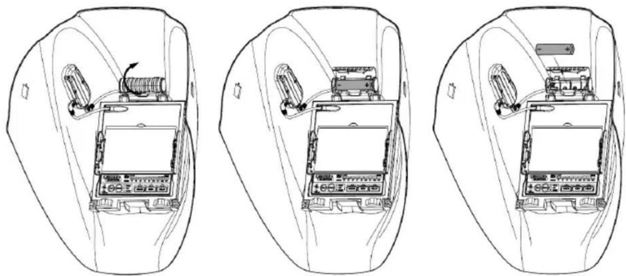
The LED uses a standard AA battery. To replace the battery, open the battery compartment door as shown in the image below. Orient the battery as shown.
CARTRIDGE OPERATION/FEATURES
Variable Shade Control
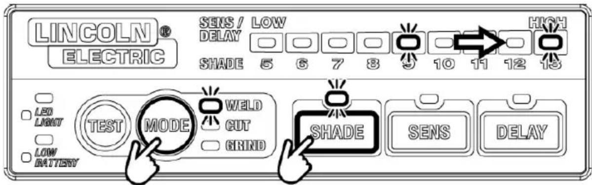
The shade can be adjusted from shade 5 to 13 based upon welding process or application (refer to Shade selection chart on Page 10). Press the MODE button to select Weld Mode. Press the SHADE button to select the desired shade between 9 and 13 displayed on the LED scale. The scale will illuminate green for Shade Control Mode.
text_image
LINCOLN® ELECTRIC SENS / LOW DELAY SHADE 5 6 7 8 9 10 11 12 13 LED LIGHT TEST MODE WELD CUT GRIND SHADE SENS DELAYPress the MODE button to select Cut Mode. Press the SHADE button to select the desired shade between 5 and 8 displayed on the LED scale. The scale will illuminate green for Shade Control Mode.

text_image
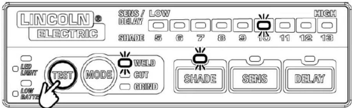
LINCOLN® ELECTRIC SENS / LOW DELAY SHADE 5 6 7 8 9 10 11 12 13 HIGH LED LIGHT TEST MODE WELD CUT GRIND SHADE SENS DELAY LOW BATTERYTest Button
Press and hold test to preview shade selection before welding. When released, the viewing window will automatically return to the light state (3.5 Shade).
text_image
LINCOLN® ELECTRIC SENS / LOW DELAY SHADE 5 6 7 8 9 10 11 12 13 HIGH LED LIGHT TEST MODE WELD CUT GRIND SHADE SENS DELAY LOW BATTESensitivity Control
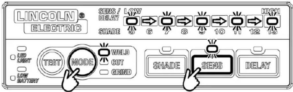
Press the MODE button to select Weld or Cut Mode. Adjust the light sensitivity by pressing the SENS button to select Sensitivity Control Mode. Press the SENS button to select the desired sensitivity level displayed on the LED scale. The scale will illuminate orange for Sensitivity Control Mode. HIGH increases the sensitivity which makes the ADF cartridge more sensitive to light. When the helmet is used in the presence of excess ambient light or with another welding machine close by, improved helmet performance can be obtained with a lower setting indicated by LOW. There are 5 increments of sensitivity control.
text_image
LINCOLN® ELECTRIC SENS / DELAY SHADE LOW 6 7 8 9 10 11 12 13 HIGH LED LIGHT TEST MODE WELD CUT GRIND SHADE SENS DELAYDelay Control
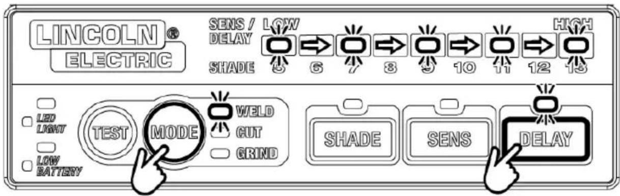
This control is designed to protect the welder's eyes from the strong residual rays after welding. Changing the delay settings will vary the dark to light time between 0.1 seconds (LOW) and 1.0 seconds (HIGH). Press the MODE button to select Weld or Cut Mode. Press the DELAY button to select Delay Control Mode. Press the DELAY button to select the desired sensitivity level displayed on the LED scale. The scale will illuminate orange for Delay Control Mode. There are 5 increments of delay control. The HIGH setting is recommended for high amperage applications where the weld puddle is still very bright after the welding arc has ceased and for situations where the filter may be temporarily blocked from seeing the welding arc.
text_image
LINCOLN® ELECTRIC SENS / LOW DELAY SHADE 5 6 7 8 9 10 11 12 13 LED LIGHT TEST MODE WELD GUT GRIND SHADE SENS DELAY LOW BATTERYPower
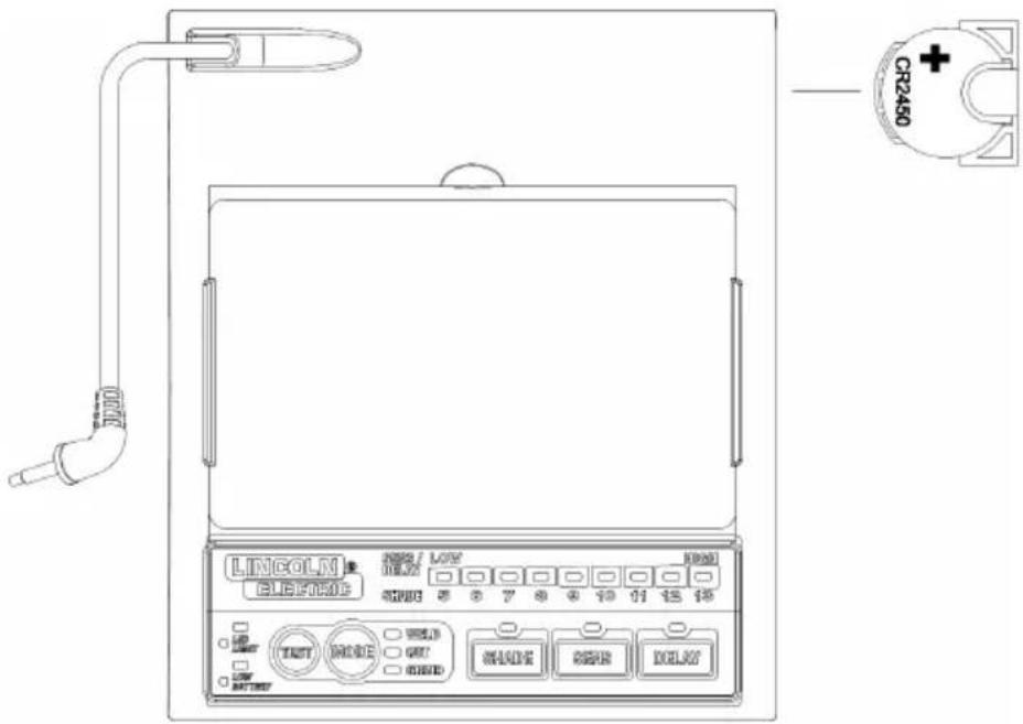
This ADF is powered by a replaceable battery and solar power. The battery is located at the top corner of the ADF cartridge. Replace the battery when the LOW BATTERY light is lit. See the specification chart on page 3 for the type of battery required.
text_image
CR240 LINCOLN ELECTRIC OFF LWY 1000 5 6 7 8 9 10 11 12 13 TEST MODE OFF MADK RESET DELAYHELMET CARE AND MAINTENANCE
Cleaning: Clean helmet by wiping with a soft cloth. Clean cartridge surfaces regularly. Do not use strong cleaning solutions. Clean sensors and solar cells with soapy water solution and a clean cloth and wipe dry with a lint-free cloth. Do NOT submerge shade cartridge in water or other solution.
Storage: Store in a clean, dry location.
SHADE GUIDE SETTINGS
| GUIDEFORSHADENUMBERS | ||||
| OPERATIONELECTRODESIZEARCMINIMUMSUGGESTED(1)1/32in.(mm)CURRENT(A)PROTECTIVESHADENO. | ||||
| SHADE(COMFORT) | ||||
| Shielded metal arc welding | Less than 3 (2.5)3-5 (2.5–4)5-8 (4–6.4) 160-250More than 8 (6.4) | Less than 6060-16010250-550 | 781211 | –1014 |
| Gas metal arc welding and flux cored arc welding | Less than 6060-160160-250250-500 | 7101010 | –111214 | |
| Gas tungsten arc welding | Less than 5050-150150-500 | 8810 | 101214 | |
| Air carbonArc cutting | (Light)(Heavy) | Less than 500500-1000 | 1011 | 1214 |
| Plasma arc welding | Less than 2020-100100-400400-800 | 681011 14 | 6 to 81012 | |
| Plasma arc cutting | (Light)^(2) (Medium)^(2) (Heavy)^(2) | Less than 300300-400400-800 | 8910 | 91214 |
| Torch brazing | – | – | 3 or 4 | |
| Torch soldering | – | – | 2 | |
| Carbon arc welding | – | – | 14 | |
| PLATETHICKNESSin. mm | ||||
| Gas weldingLightMediumHeavy | Under 1/81/8 to 1/2Over 1/2 | Under 3.23.2 to 12.7Over 12.7 | 4 or 55 or 66 or 8 | |
| Oxygen cuttingLightMediumHeavy | Under 11 to 6Over 6 | Under 2525 to 150Over 150 | 3 or 44 or 55 or 6 | |
(1) As a rule of thumb, start with a shade that is too dark, then go to a lighter shade which gives sufficient view of the weld zone without going below the minimum. In oxyfuel gas welding or cutting where the torch produces a high yellow light, it is desirable to use a filter lens that absorbs the yellow or sodium line the visible light of the (spectrum) operation.
(2) These values apply where the actual arc is clearly seen. Experience has shown that lighter filters may be used when the arc is hidden by the workpiece.
Data from ANSI Z49.1-2005
If your helmet does not include any one of the shades referenced above, it is recommended you use the next darker shade.
CARTRIDGE AND LENS REPLACEMENT
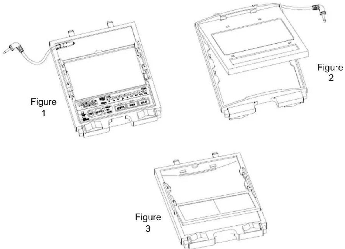
Replacing Front Clear Cover Lens: Replace the front cover lens if it is damaged. Remove ADF holder assembly per Figure 1. Remove front cover lens from helmet assembly. Carefully remove gasket from cover lens. Install new cover lens into gasket and assemble to helmet shell. Make sure to assemble cover lens and gasket into helmet shell the same way as it was removed.
Replacing Inside Clear Lens: Replace the inside clear lens if it is damaged. Place your fingernail in recess above cartridge view window and flex lens upwards until it releases from edges of cartridge view window.
Change the Shade Cartridge: Remove ADF holder assembly from helmet shell. See figure 1 for removal. Flex bottom end of the ADF holder to allow ADF cartridge to be remove from frame. Install new ADF cartridge into frame per figure 2 below. Make sure that the ADF cartridge is inserted in ADF holder correctly as shown. Install ADF holder assembly into helmet shell.
INSTALLING AN AFTERMARKET MAGNIFYING LENS:
Simply slide the magnifying lens into the short rail located on the sides of ADF holder per Figure 3.
text_image
Figure 1 Figure 2 Figure 311
TROUBLESHOOTING GUIDE
Test your shade cartridge prior to welding by directing the front of the cartridge toward a bright source of light. Then, using your fingers, rapidly cover and uncover the sensors. The cartridge should darken momentarily as the sensor is exposed. A torch striker can also be used.
| PROBLEM | POSSIBLE CAUSE $OLUTION | |
| Difficult to see through filter. Fr | Front cover lens dirty. Clean or replace front cover lens. | |
| Cartridge dirty. Clean the Auto | -Darkening cartridge with soapy water solution and soft cloth. | |
| Filter does not darken when arc is struck. | Sensitivity is set too low. Adjust sensitivity to required level. | |
| Front cover lens dirty. Clean or replace front cover lens. | ||
| Front cover lens is damaged. | Check for cracked or pitted front cover lens and replace as required. | |
| Sensors are blocked or Solar panel is blocked. | Make sure you are not blocking the sensors or solar panels with your arm or other obstacle while welding. Adjust your position so that the sensors can see the weld arc. | |
| Grind Mode Selected Make sure proper shade is selected. | ||
| Filter darkening without arc being struck. | Sensitivity set too high. Adjust sensitivity to required level. | |
| Filter remains dark after completing a weld. | Delay time set too high. Adjust delay time to required level. | |
| Helmet will not switch to grind mode after pressing button. | Button was not held for 3 seconds. | Press and hold button for 3 seconds. |
| Plug-in jack from filter is not completely inserted in the button port. | Remove plug-in jack from the button port and re-insert it into the port. | |
| Filter does not darken when TEST button is pushed. | Low battery. Replace battery. | |
| LED indicator light flashes, but the LED will not turn on after pressing button. | Low battery. | Replace AA Battery. |
| Plug-in jack from filter is not completely inserted in the button port. | Remove plug-in jack from the button port and re-insert it into the port. | |
| WARNING | ||
ADF is cracked. Weld spatter is damaging the filter. Weld spatter is damaging the filter. | Cease (STOP) using this product if this problem exists. UV/IR protection may be compromised resulting in burns to the eyes and skin. | |
| Missing, damaged, broken, cracked or distorted front cover lens. | Replace front cover lens as needed. | |
WARRANTY INFORMATION - Reference IMWS1 included in Literature.
SPATTER DAMAGE IS NOT COVERED BY WARRANTY:
Do not use this product without the correct protective clear lenses installed properly on both sides of the Auto-Darkening Filter cartridge (ADF). The clear lenses supplied with this helmet are properly sized to work with this product and substitutions from other suppliers should be avoided.
REPLACEMENT PARTS
text_image
Technical diagram of a car's internal components with numbered parts, including engine, dashboard, and battery modules.| ITEM | PART NO. | DESCRIPTION | QTY |
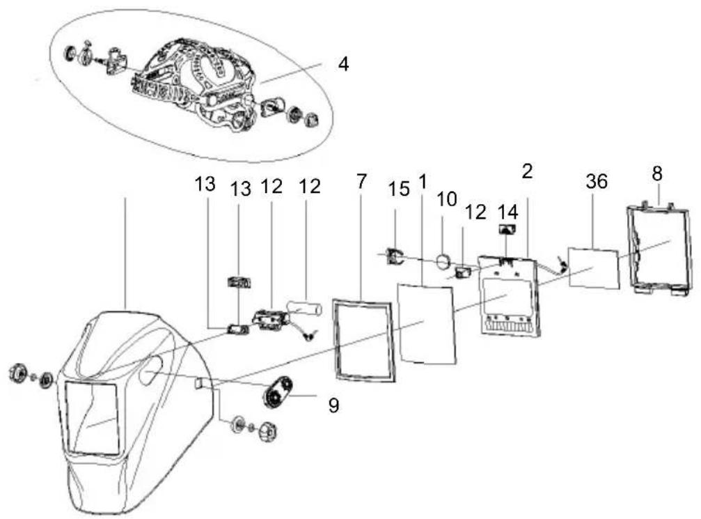
| 1 | KP2898-1 | OUTSIDE CLEAR LENS (PKG. QTY: 5) | 1 |
| 2 | KP2932-5 | ADF CARTRIDGE | 1 |
| 3 | KP2931-1 | INSIDE CLEAR LENS (PKG. QTY: 5) | 1 |
| 4 | KP4470-1 | HEADGEAR ASSEMBLY (INCLUDING SWEATBAND & RETROFIT WASHER) | 1 |
| 5* | KP2930-1 | SWEATBAND (PKG. QTY: 2) | 1 |
| 6 | KP4560-2 | GLOSSY BLACK REPLACEMENT SHELL | 1 |
| 7 | S27978-206 | OUTSIDE CLEAR LENS SEAL | 1 |
| 8 | S27978-153 | ADF HOLDER | 1 |
| 9 | KP5246-1 | GRIND BUTTON ASSEMBLY | 1 |
| 10 | KP4491-1 | REPLACEMENT BATTERY | 1 |
| 11* | KP4541-1 | HEADGEAR CUSHIONED BACK PAD (PKG QTY 2) | 1 |
| 12 | KP5245-1 | LED LIGHT KIT | 1 |
| 13 | S27978-211 | LED BATTERY HOUSING ATTACHED COVER | 1 |
| 14 | S27978-217 | LED ATTACHMENT COVER | 1 |
| 15 | S27978-218 | ADF BATTERY CLIP | 1 |
*Not illustrated
| OPTIONAL ACCESSORIES | ||
| PART NO. | DESCRIPTION | QTY |
| KP3046-100 | CHEATER LENS 1.00 MAGNIFICATION | 1 |
| KP3046-125 | CHEATER LENS 1.25 MAGNIFICATION | 1 |
| KP3046-150 | CHEATER LENS 1.50 MAGNIFICATION | 1 |
| KP3046-175 | CHEATER LENS 1.75 MAGNIFICATION | 1 |
| KP3046-200 | CHEATER LENS 2.00 MAGNIFICATION | 1 |
| KP3046-225 | CHEATER LENS 2.25 MAGNIFICATION | 1 |
| KP3046-250 | CHEATER LENS 2.50 MAGNIFICATION | 1 |
| KP3047-1 | HALO STYLE HARD HAT ADAPTER | 1 |
| KP3486-1 | SLOTTED HARD HAT ADAPTER | 1 |
 |  |  |  | ||||
| WARNING | ● Do not touch electrically live parts of electrode with skin or wet clothing.● Insulate yourself from work and ground. | ● Keep flammable materials away. | ● Wear eye, ear and body protection. | ||||
| SpanishAVISO DE PRECAUCION | ● No toque las partes o los electrodos bajo carga con la piel o ropa moja-da.● Aislese del trabajo y de la tierra. | ● Mantenga el material combustible fuera del área de trabajo. | ● Protéjase los ojos, los oídos y el cuerpo. | ||||
| FrenchATTENTION | ● Ne laissez ni la peau ni des vête-ments mouillés entrer en contact avec des pièces sous tension.● Isolez-vous du travail et de la terre. | ● Gardez à l'écart de tout matériel inflammable. | ● Protégez vos yeux, vos oreilles et votre corps. | ||||
| GermanWARNUNG | ● Berühren Sie keine stromführenden Teile oder Elektroden mit Ihrem Körper oder feuchter Kleidung!● Isolieren Sie sich von den Elektroden und dem Erdboden! | ● Entfernen Sie brennbarres Material! | ● Tragen Sie Augen-, Ohren- und Kör-perschutz! | ||||
| PortugueseATENÇÃO | ● Não toque partes elétricas e elec-trodos com a pele ou roupa molha-da.● Isole-se da peça e terra. | ● Mantenha inflamáveis bem guarda-dos. | ● Use proteção para a vista, ouvido e corpo. | ||||
| Japanese注意事項 | ● 通電中の電気部品、又は溶材にヒフやぬれた布で触れないこと。● 施工物やアースから身体が絶縁されている様にして下さい。 | ● 燃えやすいものの側での溶接作業は絶対にしてはなりません。 | ● 目、耳及び身体に保護具をして下さい。 | ||||
| Chinese警告 | ● 皮肤或濕衣物切勿接觸帶電部件及錚條。● 使你自己與地面和工件絶縁。 | ● 把一切易燃物品移離工作場所。 | ● 佩戴眼、耳及身體勞動保護用具。 | ||||
| Korean위험 | ● 전도체나 용접봉을 젖은 형갑 또는 피부로 절대 접촉치 마십시오.● 모재와 접지를 접촉치 마십시오. | ● 인화성 물질을 접근 시키지 마시요. | ● 눈、귀와 몬에 보호장구를 착용하십시오. | ||||
| Arabicتحذير | ● لا تلمس الاجزاء التي يسري فيها التيار ● الكهربائي أو الاكترود ب JFKد الجسم أو بالملابس المبللة بالعاء. ● ضع عازلا على جسمك خلال العمل. ● | ● ضع #: ● ضع #: ● ضع #: ● ضع #: ● ضع #: ● ضع #: ● ضع #: ● ضع #: ● ضع #: ● ضع #: ● ضع #: ● ضع #: ● ضع #: ● ضع #: ● ضع #: ● ضع #: ● ضع #: ● ضع #: ● ضع #: ● ضع #: ● ضع #: ● ضع #: ● ضع #: ● ضع #: ● ضع #: ● ضع #: ○ ● ضع #: ○ ● ضع #: ○ ● ضع #: ○ ● ضع #: ○ ● ضع #: ○ ● ضع #: ○ ● ضع #: ○ ● ضع #: ○ ● ضع #: ○ ● ضع #: ○ ● ضع #: ○ ● ضع #: ○ ● ضع #: ○ ● ضع #: ○ ● ضع #: ○ ● ضع #: ○ ● ضع #: ○ ● ضع #: ○ ● ضع #: ○ ● ضع #:○ ● ضع #: ○ ● ضع #: ○ ● ضع #: ○ ● ضع #: ○ ● ضع #: ○ ● ضع #: ○ ● ضع #: ○ ● ضع #: ○ ● ضع #: ○ ● ضع #: ○ ● ضع #: ○ ● ضع #: ○ ● ضع #: ○ ● ضع #: ○ ● ضع #: ○ ● ضع #: ○ ● ضع #: ○ ● ضع #: ○ ● ضع #: ○ ● ضع #: O ● ضع #: ○ ● ضع #: ○ ● ضع #: ○ ● ضع #: ○ ● ضع #: ○ ● ضع #: ○ ● ضع #: ○ ● ضع #: ○ ● ضع #: ○ ● ضع #: ○ ● ضع #: ○ ● ضع #: ○ ● ضع #: ○ ● ضع #: ○ ● ضع #: ○ ● ضع #: ○ ● ضع #: ○ ● ضع #: ○ ● ضع #: ○ ● ضع #: ◎ ● ضع #: ◎ ● ضع #: ◎ ● ضع #: ◎ ● ضع #: ◎ ● ضع #: ◎ ● ضع #: ◎ ● ضع #: ◎ ● ضع #: ◎ ● ضع #: ◎ ● ضع #: ◎ ● ضع #: ◎ ● ضع #: ◎ ● ضع #: ◎ ● ضع #: ◎ ● ضع #: ◎ ● ضع #: ◎ ● ضع#: ◎ ● ضع #: ◎ ● ضع #: ◎ ● ضع #: ◎ ● ضع #: ◎ ● ضع #: ◎ ● ضع #: ◎ ● ضع #: ◎ ● ضع #: ◎ ● ضع #: ◎ ● ضع #: ◎ ● ضع #: ◎ ● ضع #: ◎ ● ضع #: ◎ ● ضع #: ◎ ● ضع #: ◎ ● ضع #: ◎ ● Sunshine: ◎ ● ضع #: ◎ ● Sunshine: ◎ ● ضع #: ◎ ● Sunshine: ◎ ● ضع #: ◎ ● Sunshine: ◎ ● ضع #: ◎ ● Sunshine: ◎ ● ضع #: ◎ ● Sunshine: ◎ ● ضع #: ◎ ● Sunshine: ◎ ● ضع #: ◎ ● Sunshine: ◎ ● ضع #: ◎ ● Sunshine: ◎ ● ضع #: ◎ ● Sunshine:◇ ◎ ● ◎ ● ◎ ● ◎ ● ◎ ● ◎ ● ◎ ● ◎ ● ◎ ● ◎ ● ◎ ● ◎ ● ◎ ● ◎ ● ◎ ● ◎ ● ◎ ● ◎ ● ◎ ● ◎ ● ◎ ● ◎ ● ◎ ● ◎ ● ◎ ● ◎ ● ◎ ● ◎ ● ◎ ● ◎ ● ◎ ● ◎ ● ◎ ● ◎ ●◆ ◎ ● ◎ ● ◎ ● ◎ ● ◎ ● ◎ ● ◎ ● ◎ ● ◎ ● ◎ ● ◎ ● ◎ ● ◎ ● ◎ ● ◎ ● ◎ ● ◎ ● ◎ ● ◎ ● ◎ ● ◎ ● ◎ ● ◎ ● ◎ ● ◎ ● ◎ ● ◎ ● ◎ ● ◎ ● ◎ ● ◎ ● ◎ ● ◎ ●◇ ◎ ● ◎ ● ◎ ● ◎ ● ◎ ● ◎ ● ◎ ● ◎ ● ◎ ● ◎ ● ◎ ● ◎ ● ◎ ● ◎ ● ◎ ● ◎ ● ◎ ● ◎ ● ◎ ● ◎ ● ◎ ● ◎ ● ◎ ● ◎ ● ◎ ● ◎ ● ◎ ● ◎ ● ◎ ● ◎ ● ◎ ● ◎ ● ◎● ◎ ● ◎ ● ◎ ● ◎ ● ◎ ● ◎ ● ◎ ● ◎ ● ◎ ● ◎ ● ◎ ● ◎ ● ◎ ● ◎ ● ◎ ● ◎ ● ◎ ● ◎ ● ◎ ● ◎ ● ◎ ● ◎ ● ◎ ● ◎ ● ◎ ● ◎ ● ◎ ● ◎ ● ◎ ● ◎ ● ◎ ● ◎ ● ◎ ● □ ◎ ● ◎ ● ◎ ● ◎ ● ◎ ● ◎ ● ◎ ● ◎ ● ◎ ● ◎ ● ◎ ● ◎ ● ◎ ● ◎ ● ◎ ● ◎ ● ◎ ● ◎ ● ◎ ● ◎ ● ◎ ● ◎ ● ◎ ● ◎ ● ◎ ● ◎ ● ◎ ● ◎ ● ◎ ● ◎ ● ◎ ● ◎ ● ◎ ● | |||||
READ AND UNDERSTAND THE MANUFACTURER'S INSTRUCTION FOR THIS EQUIPMENT AND THE CONSUMABLES TO BE USED AND FOLLOW YOUR EMPLOYER'S SAFETY PRACTICES.
CUSTOMER ASSISTANCE POLICY
The business of The Lincoln Electric Company is manufacturing and selling high quality welding equipment, consumables, and cutting equipment. Our challenge is to meet the needs of our customers and to exceed their expectations. On occasion, purchasers may ask Lincoln Electric for advice or information about their use of our products. We respond to our customers based on the best information in our possession at that time. Lincoln Electric is not in a position to warrant or guarantee such advice, and assumes no liability, with respect to such information or advice. We expressly disclaim any warranty of any kind, including any warranty of fitness for any customer's particular purpose, with respect to such information or advice. As a matter of practical consideration, we also cannot assume any responsibility for updating or correcting any such information or advice once it has been given, nor does the provision of information or advice create, expand or alter any warranty with respect to the sale of our products.
Lincoln Electric is a responsive manufacturer, but the selection and use of specific products sold by Lincoln Electric is solely within the control of, and remains the sole responsibility of the customer. Many variables beyond the control of Lincoln Electric affect the results obtained in applying these types of fabrication methods and service requirements.
Subject to Change – This information is accurate to the best of our knowledge at the time of printing. Please refer to www.lincolnelectric.com for any updated information.
natural_image
Black welding helmet with digital display, no visible text or symbols on the helmet itselfLES IMAGES PEUVENT VARIER

natural_image
Illustration of a person in protective gear using a tool to generate red light from a lamp (no text or symbols)natural_image
Silhouette of a worker in protective gear holding tools and a briefcase (no text or symbols)PORTEZ UN DISPOSITIF DE PROTECTION ADÉQUAT POUR LES YEUX, LES OREILLES ET LE CORPS
natural_image
Silhouette of a person with a medical cross symbol inside, next to a downward arrow and a small figure (no text or symbols)natural_image
Technical line drawing of a mechanical component with gears and a bracket (no text or symbols)natural_image
Technical line drawing of a mechanical component with no visible text or symbolstext_image
Figure 1 Figure 2 Figure 3GUIDE DE DÉPANNAGE
text_image
Exploded view diagram of a car's internal components with numbered parts for identification| ARTICLE | No DE PIECE. | DESCRIPTION | QTE |
| 1 | KP2898-1 | LENTILLE TRANSPARENTE EXTERIEURE (QTE PAR PAQUET : 5) | 1 |
| 2 | KP2932-5 | CARTOUCHE DE FILTRE A LENTILLE PHOTOSENSIBLE | 1 |
| 3 | KP2931-1 | LENTILLE TRANSPARENTE INTÉRIEURE (QTE DU PAQUET : 5) | 1 |
| 4 | KP4470-1 | ENSEMBLE DE SERRE-TÊTE (Y COMPRIS LE BANDEAU ANTISUDATION ET LA RONDELLE DE REMISE À NEUF) | 1 |
| 5* | KP2930-1 | BANDEAU ANTISUDATION (QTE DU PAQUET : 2) | 1 |
| 6 | KP4560-2 | COQUE DE REMPLACEMENT NOIRE LUSTREE | 1 |
| 7 | S27978-206 | JOINT D'ÉTANCHÉITÉ EXTÉRIEUR TRANSPARENT | 1 |
| 8 | S27978-153 | SUPPORT DU FILTRE A LENTILLE PHOTOSENSIBLE | 1 |
| 9 | KP5246-1 | ASSEMBLAGE DE BOUTON DE MEULAGE | 1 |
| 10 | KP4491-1 | PILE DE RECHANGE | 1 |
| 11* | KP4541-1 | COUSSINET ARRIÈRE REMBOURRE POUR SERRE-TÊTE (QTÉ PAR PAQUET : 2) | 1 |
| 12 | KP5245-1 | TROUSSE D'ECLAIRAGE A DEL | 1 |
| 13 | S27978-211 | COUVERCLE FIXÉ AU BOÎTIER DE PILE DE LA DEL | 1 |
| 14 | S27978-217 | COUVERCLE DE FIXATION DE LA DEL | 1 |
| 15 | S27978-218 | CONNECTEUR DE LA BATTERIE DE LA LUNETTE PHOTOSENSIBLE | 1 |
*Non illustré
| ACCESSOIRES OPTIONNELS | ||
| No DE PIECE. | DESCRIPTION | QTE |
| KP3046-100 | LENTILLE TRICHEUR 1,00 D'AGRANDISSEMENT | 1 |
| KP3046-125 | LENTILLE TRICHEUR 1,25 D'AGRANDISSEMENT | 1 |
| KP3046-150 | LENTILLE TRICHEUR 1,50 D'AGRANDISSEMENT | 1 |
| KP3046-175 | LENTILLE TRICHEUR 1,75 D'AGRANDISSEMENT | 1 |
| KP3046-200 | LENTILLE TRICHEUR 2,00 D'AGRANDISSEMENT | 1 |
| KP3046-225 | LENTILLE TRICHEUR 2,25 D'AGRANDISSEMENT | 1 |
| KP3046-250 | LENTILLE TRICHEUR 2,50 D'AGRANDISSEMENT | 1 |
| KP3047-1 | ADAPTATEUR DE CASQUE DUR DE STYLE HALO | 1 |
| KP3486-1 | ADAPTATEUR POUR CASQUE DUR À FENTE | 1 |
 |  |  |  |
| WARNING | ● Do not touch electrically live parts or electrode with skin or wet clothing.● Inudate yourself from work and ground. | ● Keep fluorescent materials every. | ● Wear eyes ear and body protection. |
| Cap agricilAVISO DE PRECAUCION | ● No torque les parties ou les électrodes bajo carga con la piede rouge mege de sa.● Ainsse de trabujay de la terre. | ● Mantenga si material combinable terre del área de trabajo. | ● Protégue les opres, los cédits y el cuerpo. |
| FrançaiseATTENTION | ● Are insurand le moment des véléments modifiés entre en contact avec des piéons sous tend on.● l'indat-von du travail et de la terre. | ● Restes à l'acart de tu un matériel inflammable. | ● Protégue van year, ses amélles et autre corps. |
| AfrikaandAVERTISSEMENT | ● Sedhmen Sie keine strom Ekmorden Talle oder Ektrodes nonl Parent/Körper oder kouteir Kielung!● Iadkenn Sie sich von den Ektrodes und dem Erdbesert | ● Erdkenn Sie terribumes Material | ● Tragen Sie Augen, Osten- und Non-perschutzaf |
| PortugatsATENÇÃO | ● Não torque partes siktifica e elec tendos sont a pile ou roupe metho-de.● Iade-se de depa e terre. | ● Mantena influminiva terrquardé dos. | ● Use protégie para a vista ouvràle corps. |
| Supérie注意事項 | ● 通電中の電気部品、又は溶材にヒフやぬれた巻で触れないこと。● 施工物やアースから身体が動機されている様にして下さい。 | ● 燃えやすいものの側での演操作業は離対にしてはありません。 | ● 目、耳及び身体に保護具をして下さい。 |
| Chenes警告 | ● 皮肤或黑色衣物切勿能擦毒電部件及評価。● 使你自己與地面和工作絕醒。 | ● 把一切易燃物品移離工作場所。 | ● 保護機、耳及身體等助保護用具。 |
| Covers위험 | ● 전도하나 용層분을 찾ن 喜업 또는 피루로 缠대 접촉치 미십시오.● コ재의 접지를 접촉치 미십시오. | ● 전화성 물질을 접근 시키지 미시오. | ● 눈、마와 못에 보호장구를 적용하십시오. |
| Auteتحذير | ● لا تىस ا Grazées ثى يسرى فيها التبار لثەھرلىيى وى الالترّدود، بجتك النبسموأو يالملايسى المبلقة پېتماد.● ضع عازلا على جيمك خالل العمل. | ● ضع اللواد القابلة للاشتمال في مChannel بعد. | ● ضع أورات وملابس وقابلة على هبنده وان pipelines ● وجست. |
READ AND UNDERSTAND THE MANUFACTURER'S INSTRUCTION FOR THIS EQUIPMENT AND THE CONSUMABLES TO BE USED AND FOLLOW YOUR EMPLOYEES SAFETY DRACTICES
- Keep your head out of fumes.
- Use ventilation or exhaust to remove fumes from breathing zone.
- Los humos fuera de la zona de res- piración.
- Mantenga la cabeza fuera de los humos. Utilice ventilación o aspiración para gases.
- Gardez votre tête à distance des émanations. I Utilisez une ventilation ou un échappement pour éliminer les émanations de la zone
• de respiration.
● Vermeiden Sie das Einatmen von Schweibrauch! - Sorgen Sie für gute Be- und Entlüftung des Arbeitsplatzes!
- Mantenha seu rosto da fumaça.
- Use ventilação e exhaustão para remover fumo da zona respiratória.
● Turn power off before servicing.
- Desconectar el cable de ali- mentación de poder de la máquina antes de iniciar cualquier servicio.
- Débranchez le courant avant l'entretien.
- Strom vor Wartungsarbeiten abschalten! (Netzstrom völlig öff- nen; Maschine anhalten!)
- Não opere com as tampas removidas.
- Desligue a corrente antes de fazer serviço.
- Não toque as partes elétricas nuas.
- Do not operate with panel open or guards off.
- No operar con panel abierto o guardas quitadas.
- N'opérez pas avec les panneaux ouverts ou avec les dispositifs de protection enlevés.
● Anlage nie ohne Schutzgehäuse oder Innenschutzverkleidung in Betrieb setzen! - Mantenha-se afastado das partes moventes.
- Não opere com os paineis abertos ou guardas removidas.
WARNING
Espagnol
AVISO DE PRECAUCION
Français
ATTENTION
Allemand
AVERTISSEMENT
Portugais
ATENÇÃO
Japonais
注意事項
Chinois
警告
Coréen
LEIA E COMPREENDA AS INSTRUÇÕES DO FABRICANTE PARA ESTE EQUIPAMENTO E AS PARTES DE USO, E SIGA AS PRÁTICAS DE SEGURANÇA DO EMPREGADOR.
POLITIQUE D'AIDE À LA CLIENTÈLE
natural_image
Black welding helmet with visible display screen and branding (no readable text or symbols beyond branding)LOS GRÁFICOS PUEDEN VARIAR

Registre su máquina:
www.lincolnelectric.com/register
natural_image
Illustration of a person in protective gear using a tool to drive a glowing red-orange substance from a platform (no text or symbols)UTILICE VENTILACIÓN
natural_image
Silhouette of a person in military-style attire holding a tool and helmet (no text or symbols)text_image
Diagram showing three scenarios of a parking garage with no parking, including a house icon and a vehicle symbol.
LOS CAMPOS ELÉCTRICOS Y MAGNÉTICOS PUEDEN SER PELIGROSOS
natural_image
Silhouette of a person with a medical device and a small figure, no text or symbols presentnatural_image
Technical line drawing of a mechanical component with gears and a handle (no text or symbols)natural_image
Technical line drawing of a mechanical component with gears and a bracket (no text or symbols)natural_image
Line drawing of a car interior showing internal components like a battery pack and coiled cable (no text or symbols)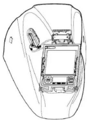
natural_image
Line drawing of a car interior showing the dashboard and rearview compartment (no text or symbols)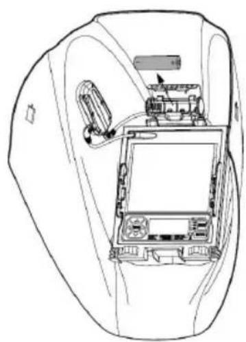
natural_image
Line drawing of a car interior showing internal components like dashboard, camera, and steering wheel (no text or symbols)USO/CARACTERÍSTICAS DEL CARTUCHO
Control de tono variable
text_image
Technical diagram of a car's internal components with numbered parts, including engine, dashboard, and control panel.| ARTICULO | N.° DE PIEZA | DESCRIPCIÓN | CANT. |
| 1 | KP2898-1 | LENTES TRANSPARENTES EXTERIORES (CANT.PAQUETE: 5) | 1 |
| 2 | KP2932-5 | CARTUCHO ADF | 1 |
| 3 | KP2931-1 | LENTE INTERIOR TRANSPARENTE (PAQ. CANT.: 5) | 1 |
| 4 | KP4470-1 | CONJUNTO DE CASCO (INCLUYE BANDA DETRANSPIRACIÓN Y ARANDELA DE RETROADAPTACIÓN | 1 |
| 5* | KP2930-1 | BANDA DE TRANSPIRACION (PAQUETE. CANT.: 2) | 1 |
| 6 | KP4560-2 | CUBIERTA NEGRO BRILLANTE PROTECTORA DEREMPLAZO | 1 |
| 7 | S27978-206 | SELLO DE LENTE EXTERNA TRANSPARENTE | 1 |
| 8 | S27978-153 | SOPORTE ADF | 1 |
| 9 | KP5246-1 | CONJUNTO DE BOTON DE RECTIFICADO | 1 |
| 10 | KP4491-1 | BATERIA DE REEMPLAZO | 1 |
| 11* | KP4541-1 | ALMOHADILLA DE RESPALDO ACOLCHADA DEL CASCO(CANT. PAQUETE 2) | 1 |
| 12 | KP5245-1 | KIT DE LUZ LED | 1 |
| 13 | S27978-211 | CUBIERTA DE LA CARCASA DE LA BATERIA DEL LED | 1 |
| 14 | S27978-217 | CUBIERTA DE FIJACION DE LED | 1 |
| 15 | S27978-218 | CLIP DE BATERIA DE ADF | 1 |
*No ilustrado