Dual Maverick 200 - Welding machine LINCOLN ELECTRIC - Free user manual and instructions
Find the device manual for free Dual Maverick 200 LINCOLN ELECTRIC in PDF.


User questions about Dual Maverick 200 LINCOLN ELECTRIC
0 question about this device. Answer the ones you know or ask your own.
Ask a new question about this device
Download the instructions for your Welding machine in PDF format for free! Find your manual Dual Maverick 200 - LINCOLN ELECTRIC and take your electronic device back in hand. On this page are published all the documents necessary for the use of your device. Dual Maverick 200 by LINCOLN ELECTRIC.
USER MANUAL Dual Maverick 200 LINCOLN ELECTRIC
MANUEL D'INSTRUCTIONS
Dual Maverick® 200/200X
natural_image
Technical line drawing of an industrial server chassis with visible internal components and mounting brackets (no text or labels)APPLICATIONS RECOMMANDÉES......C-4
GÉNÉRATEUR,......C-4
INSTRUCTION DE DÉMARRAGE AUTOMATIQUE,......C-4
PÉRIODE DE RODAGE....C-5
DÉMARRAGE ET ARRÊT DU MOTEUR......C-6
CONSOMMATION DE CARBURANT TYPIQUE...... C-6
FONCTIONNEMENT DE LA SOUDEUSE.... C-7
MISE EN PARALLÈLE...... C-11
FONCTIONNEMENT DE L'ALIMENTATION AUXILIAIRE...... C-12
FONCTIONNEMENT DE L'AFFICHAGE...... C-12
ÉCRAN D'ACCUEIL,...... C-13
SOUDAGE À LA BAGUETTE...... C-13
SOUDAGE MIG/FCAW......C-16
CROSSLINC......C-18
PISTOLET À BOBINE......C-19
MODE DE CONTRÔLE SYNERGIQUE DU PISTOLET À BOBINE....C-20
MODE IMPULSION...... C-21
MODE TEMPS DE POINTAGE....C-22
ÉCRAN D'ÉTAT DU MOTEUR......C-23
INFO MOTEUR......C-24
CONFIGURATION......C-25
SÉLECTION DE LA MACHINE...... C-30
CROSSLINC ON/OFF (MARCHE/ARRÊT)...... C-31
ÉTALONNAGE DU PISTOLET À BOBINE......C-32
KIT D'ENTRETIEN MOTEUR......C-33
MÉTRIQUES DE PRODUCTIVITÉ......C-33
ACCESSOIRES ET OPTIONS......SECTIOND
ACCESSOIRES......D-1
ENTRETIEN......SECTIONE
CONSIGNES DE SÉCURITÉ....E-1
ENTRETIEN DE ROUTINE ET PÉRIODIQUE,....E-1
ENTRETIEN DU MOTEUR....E-1
FILTRE À AIR....E-2
INSTRUCTIONS D'ENTRETIEN DU FILTRE À AIR....E-3
FILTRES À CARBURANT....E-5
SYSTÈME DE REFROIDISSEMENT....E-5
ENTRETIEN DES PLAQUES SIGNALÉTIQUES / AUTOCOLLANTS D'AVERTISSEMENT,......E-6
ENTRETIEN DE LA SOUDEUSE / GÉNÉRATEUR......E-7
CHANGEMENT DE LA COURROIE DE VENTILATEUR....E-7
VIDANGE D'HUILE....E-7
MANIPULATION DE LA BATTERIE....E-8
PRÉVENTION DES DOMMAGES ÉLECTRIQUES...... E-8
PRÉVENTION DE LA DÉCHARGE DE LA BATTERIE......E-8
PRÉVENTION DU GONDOLEMENT DE LA BATTERIE,....E-9
CHARGE DE LA BATTERIE....E-9
DÉPANNAGE......SECTIONF
COMMENT UTILISER LE GUIDE DE DÉPANNAGE....F-1
GUIDE DE DÉPANNAGE.... F-2
CODES D'ERREUR CLIGNOTANTS DE DÉFAILLANCE MOTEUR SUR L'ECG....F-6
ANNEXE...... SECTIONG
SCHÉMA DE CÂBLAGE....G-1
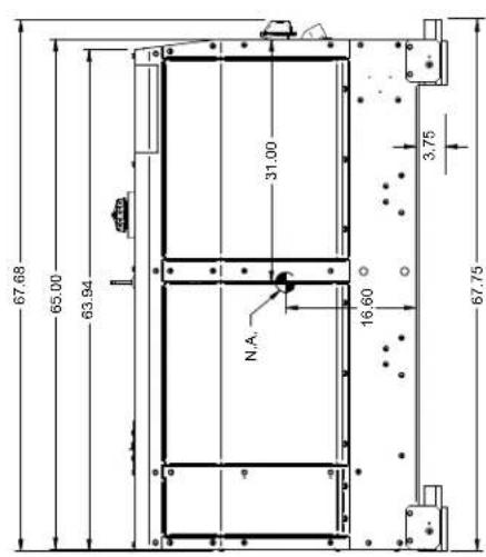
IMPRESSION DES DIMENSIONS....G-2
POLITIQUE D'AIDE À LA CLIENTÈLE
LES RENSEIGNEMENTS RELATIFS À LA SÉCURITÉ
LA SÉCURITÉ DÉPEND DE VOUS
https://www.lincolnelectric.com/register
https://www.lincolnelectric.com/locator
RENSEIGNEMENTS SUPPLÉMENTAIRES SUR LA SÉCURITÉ
natural_image
Technical line drawing of an industrial machine casing with internal components and mounting holes (no text or symbols)Illustration 1 :
INSTALLATION
natural_image
Pure electrical circuit board layout without any text, numbers, or symbolsIllustration 2 :
text_image
Technical diagram of an electronic device front panel with numbered components for identificationIllustration 3 :
text_image
Weld Output Override Remote Output OFF (OUTPUT CONTROLLED BY TORCH/FOOT PEDAL SWITCH) ON (OUTPUT ALWAYS ON) Press knob to select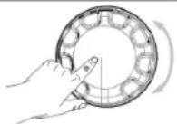
Illustration 4 :
CÂBLES DE SORTIE DE SOUDAGE
text_image
Electrode Work LeadCONFIGURATION DU SOUDAGE DE FILS, PISTOLET DÉVIDOIR
text_image
K586-1 Deluxe Gas Regulator and hose kit Work cable (part of K2150-1) Work clamp (part of K2150-1) Spool Gun with mechanical gas valve (K3569-2)Illustration 6 :
CONNEXION DE LF-72, LF-74, FLEX FEED 74 HT, FLEX FEED 84, LN-25 PRO DOUBLE ALIMENTATION AU Dual Maverick 200/200X
text_image
WIRE FEEDER A 14 PIN Operator A ENGINE WELDER Operator B 14 PIN K1797-xx CABLE ELECTRODE CABLE TO WIRE FEED UNIT TO WORK WIRE FEEDER B K1797-xx CABLE ELECTRODE CABLE TO WIRE FEED UNIT TO WORKIllustration 8 :
PRISES D'ALIMENTATION AUXILIAIRE
(CROSSLINC WIRE FEEDER)

flowchart
graph LR
    subgraph_Operator_A["Operator A"]
        A1["14 PIN CONNECTOR"] --> A2["Engine Welder"]
        A2 --> A3["6 PIN CONNECTOR"]
        A3 --> A4["14 PIN CONNECTOR"]
        A4 --> A5["Engine Welder"]
        A5 --> A6["6 PIN CONNECTOR"]
    end
    subgraph_Operator_B["Operator B"]
        B1["14 PIN CONNECTOR"] --> B2["Engine Welder"]
        B2 --> B3["6 PIN CONNECTOR"]
        B3 --> B4["14 PIN CONNECTOR"]
        B4 --> B5["Engine Welder"]
    end
    C1["CROSSLINC WIRE FEEDER"] --> E1["TO WORK"]
    E1 --> E2["EXTRONDE CABLE"]
    E2 --> E3["TO WORK"]
    E3 --> E4["EXTRONDE CABLE"]
    E4 --> F1["TO WORK"]
    F1 --> F2["EXTRONDE CABLE"]
    F2 --> F3["EXTRONDE CABLE"]
    F3 --> G1["EXTRONDE CABLE"]
    G1 --> H1["EXTRONDE CABLE"]
    H1 --> H2["EXTRONDE CABLE"]
    H2 --> I1["EXTRONDE CABLE"]
    I1 --> J1["EXTRONDE CABLE"]
    J1 --> J2["EXTRONDE CABLE"]
    J2 --> K1["EXTRONDE CABLE"]
    K1 --> L1["EXTRONDE CABLE"]
    L1 --> M1["EXTRONDE CABLE"]
    M1 --> N1["EXTRONDE CABLE"]
    N1 --> O1["EXTRONDE CABLE"]
    O1 --> P1["EXTRONDE CABLE"]
    P1 --> Q1["EXTRONDE CABLE"]
    Q1 --> R1["EXTRONDE CABLE"]
    R1 --> S1["EXTRONDE CABLE"]
    S1 --> T1["EXTRONDE CABLE"]
    T1 --> U1["EXTRONDE CABLE"]
    U1 --> V1["EXTRONDE CABLE"]
    V1 --> W1["EXTRONDE CABLE"]
    W1 --> X1["EXTRONDE CABLE"]
Illustration 9 :
(CROSSLINC REMOTE)

flowchart
graph LR
    A["Operator A"] -->|14 PIN CONNECTOR| B["Engine Welder"]
    A -->|8 PIN CONNECTOR| C["Engine Welder"]
    A -->|14 PIN CONNECTOR| D["Engine Welder"]
    A -->|8 PIN CONNECTOR| E["Engine Welder"]
    F["Operator B"] -->|14 PIN CONNECTOR| G["Engine Welder"]
    F -->|8 PIN CONNECTOR| H["Engine Welder"]
    F -->|14 PIN CONNECTOR| I["Engine Welder"]
    J["CROSSLINC WIRE FEEDER"] --> K["TO WORK"]
    L["CROSSLINC WIRE FEEDER"] --> M["TO WORK"]
    N["CROSSLINC WIRE FEEDER"] --> O["TO WORK"]
    P["CROSSLINC WIRE FEEDER"] --> Q["TO WORK"]
    R["CROSSLINC WIRE FEEDER"] --> S["TO WORK"]
    T["CROSSLINC WIRE FEEDER"] --> U["TO WORK"]
    V["CROSSLINC WIRE FEEDER"] --> W["TO WORK"]
    X["CROSSLINC WIRE FEEDER"] --> Y["TO WORK"]
    Z["CROSSLINC WIRE FEEDER"] --> AA["TO WORK"]
    AB["WORK CLIP LEAD"] --> AC["TO WORK"]
    AD["EXTRONDE CABLE"] --> AE["TO WORK"]
    AF["WORK CLIP LEAD"] --> AG["TO WORK"]
    AH["EXTRONDE CABLE"] --> AI["TO WORK"]
Illustration 10 :
UTILISATION D'APPAREILS ÉLECTRIQUES AVEC CE PRODUIT
natural_image
Technical line drawing of an internal engine assembly (no text or labels)APPLICATIONS RECOMMANDÉES
Soudage Downhill Pipe
text_image
Electrode Work Lead Electrode Work LeadSoudage TIG
text_image
Foot Pedal K870 Work Lead PTA-17, 2 Cable, K1782-2 12.5' PTA-17, 2 Cable, K1782-4 25' Work Lead PTA-17, 2 Cable, K1782-2 12.5' PTA-17, 2 Cable, K1782-4 25' Foot Pedal K870text_image
Stick Welding Press knob to selectSOUDAGE À LA BAGUETTE
flowchart
graph TD
    A["Stick Welding Basic OCV"] --> B["Stick Welding Basic OCV w Remote"]
    B --> C["Stick Welding Basic Arc is struck"]
    C --> D["Stick Welding Basic 5 seconds after arc goes out"]
    D --> E["Actual arc amps"]
    D --> F["Actual arc volts"]
    D --> G["Flashes"]

    subgraph OCVs
        H["100A"] --> I["Press knob for Options"]
        J["360B SEC UNTIL AUTO SHUTDOWN"] --> K["Press knob for Options"]
    end

    style OCVs fill:#f9f,stroke:#333,stroke-width:2px
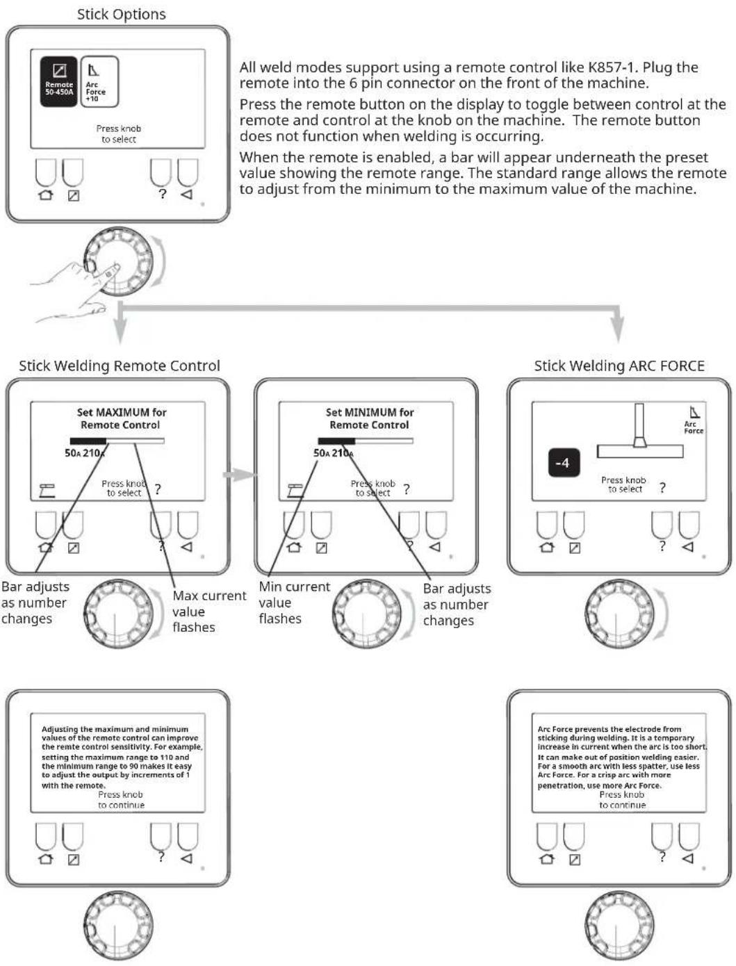
All weld modes support using a remote control like K857-1. Plug the remote into the 6 pin connector on the front of the machine.
Press the remote button on the display to toggle between control at the remote and control at the knob on the machine. The remote button does not function when welding is occurring.
When the remote is enabled, a bar will appear underneath the preset value showing the remote range. The standard range allows the remote to adjust from the minimum to the maximum value of the machine.
SOUDAGE MIG/FCAW
flowchart
graph TD
    A["MIG/FCAW-GS Welding"] --> B["MIG Welding Basic OCV"]
    B --> C["33.1v Press knob for Options"]
    C --> D["Shows present voltage"]
    D --> E["MIG Options"]
    E --> F["Press knob for select"]
    F --> G["?"]
    H["MIG Welding Basic OCV w Remote"] --> I["3600 SEC UNTIL AUTO SHUTDOWN"]
    I --> J["Press knob for Options"]
    J --> K["Shows present voltage"]
    K --> L["MIG Settings"]
    L --> M["Weld Output Override"]
    M --> N["Remote ON"]
    M --> O["Output ON"]
    P["Pinch Mode Info"] --> Q["Pinch, also called inductance, changes the rate of current rise when the electrode short circuits to the work. More pinch may reduce splatter, while less pinch makes the puddle more fluid, resulting in a flatter, smoother weld bead. Press knob to continue"]
    Q --> R["?"]
    S["Pinch Mode"] --> T["-4"]
    T --> U["Press knob to select"]
    U --> V["?"]
FONCTIONNEMENT
text_image
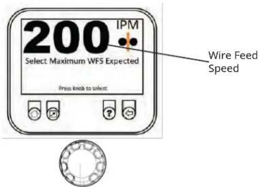
200 IPM Select Maximum WFS Expected Press limit to select: Wire Feed Speedtext_image
3600 SEC UNTIL AUTO SHUTDOWN 33.1v Output OFF Pass to Media +10 Crossline Indicator 2400 +100 1/16"PISTOLET À BOBINE
flowchart
graph TD
    A["Spool Gun Welding Basic OCV"] --> B["Spool Gun Welding Basic OCV w Remote"]
    B --> C["Spool Gun Options"]
    subgraph Spool Gun Welding Basic OCV
        D["331 in min"] --> E["23.1v"]
        F["4%"] --> G["23.1v"]
        H["E"] --> I["23.1v"]
        J["Press knob for Options"] --> K["1/16°"]
        L["Output OFF"] --> M["1/16°"]
        N["Pulse OFF"] --> O["1/16°"]
        P["Spot Time Off"] --> Q["1/16°"]
        R["Shows present wire feed speed"] --> S["23.1v"]
        T["Shows present voltage"] --> U["23.1v"]
    end
MODE DE CONTRÔLE SYNERGIQUE DU PISTOLET À BOBINE
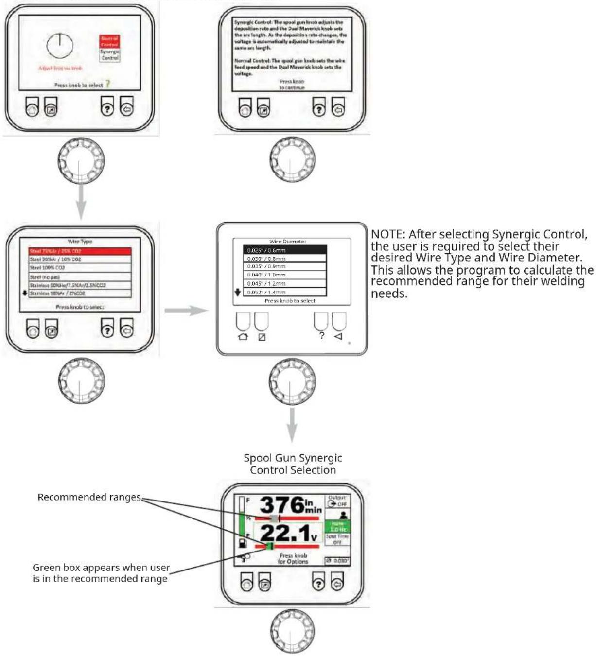
Synergic Control Selection Synergic Control Mode Info
flowchart
graph TD
    A["Adjust from wire knob\nPress knob to select?"] --> B["Wire Type\nSteel 75%Ar / 35% CO2\nSteel 90%Ar / 10% CO2\nSteel 100% CO2\nSteel (no gas)\nStainless 00%Ar/7.5%Ar/0.5%CO2\nStainless 95%Ar / ZNCO2\nPress knob to select."] --> C["Wire Diameter\n0.025"/0.6mm\n0.030"/0.8mm\n0.035"/0.9mm\n0.040"/1.0mm\n0.045"/1.2mm\n0.052"/1.4mm\nPress knob to select."] --> D["Spool Gun Synergic Control Selection"]
    D --> E["Recommended ranges\nGreen box appears when user is in the recommended range"]
MODE IMPULSION
text_image
Pulse welding is useful to lower heat input when welding thin materials or working out of position. It helps to agitate the puddle when welding aluminum and can produce a "stacked dime" weld appearance. Press knob to continue
MODE TEMPS DE POINTAGE
text_image
10.0 seconds Press knob to select
text_image
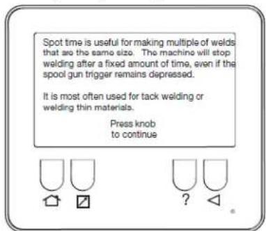
Spot time is useful for making multiple of welds that are the same size. The machine will stop welding after a fixed amount of time, even if the spool gun trigger remains depressed. It is most often used for tack welding or welding thin materials. Press knob to continue
text_image
Engine Press knob to select 80 Hours Remaining Oil Air Filter Fan Belt Fuel Filter Water Separator Press and hold knob to reset: 12.1 V0 210.5 Hrs ?INFO MOTEUR
text_image
33.1v Press knob for Options Output OFF High Main 10 XLINE READY ≤200 1/10° Engine Info OK 23°C 12.9 V 0 RPM ENGINE HOURS 0.00 Press question to navigate to Engine Info screen Press the encoder knob or the back button to return to previous screenCONFIGURATION
text_image
Setup Press Knob to select Auto-Start No Load Period Top Start Active Period Auto-Start On/Off PIN Display Brightness Diagnostic Information Press knob to selecttext_image
Display Brightness Brightness: 100 Press kindo to selecttext_image
Operator PIN OFF 8 1 2 3 Supervisor PIN OFF 8 1 2 3 Press knob to select

FONCTIONNEMENT
text_image
Variable Speed On/Off Feature: ON Press knob to select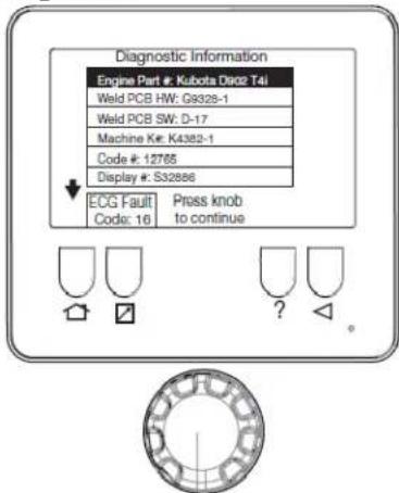
text_image
Diagnostic Information Engine Part #: Kubota D902 T4i Weld PCB HW: G9328-1 Weld PCB SW: D-17 Machine Ke: K4382-1 Code #: 12765 Display #: S32866 ECG Fault Code: 16 Press knob to continuetext_image
Ensure in Stick Mode and Output Volts > 50 Mode: Stick Welding Stud Volts: 0V Weld Amps: 1A Press knob to continue
text_image
Ensure in Single Mode and Stick Mode at 150A Setpoint Mode: Stick Welding Stud Volts: 0V Weld Amps: 2A Press knob to continue

text_image
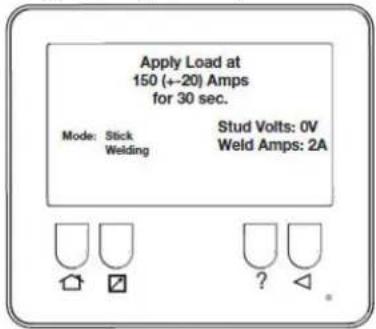
Apply Load at 150 (+-20) Amps for 30 sec. Mode: Stick Welding Stud Volts: 0V Weld Amps: 2A
SÉLECTION DE LA MACHINE
text_image
Display Brightness Diagnostic Information New PCB Calibration Variable Speed On/Off Restore Factory Settings Machine Select Press knob to select Machine Select K#: K0000-0 CODE#: 00000 Press knob to select Machine Select Welder Accepted! Press knob to continueCROSSLINC ON/OFF (MARCHE/ARRÊT)
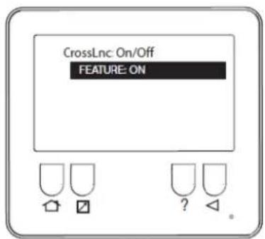
text_image
CrossLnc: On/Off FEATURE: ON
text_image
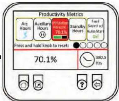
Productivity Metrics Arc Hours Auxiliary Hours Utilization Percept 70.1% Standby Hours Fuel Sayed w/ Auto-Stat Press and hold knob to reset: 70.1% 380.3 Hrs
text_image
Productivity Metrics Arc Hours Auxiliary Hours Utilization Present 70.1% Standby Hours Fuel Seated w/ Auto-Start Gas Press and hold knob to reset: 70.1% 380.5 Hrs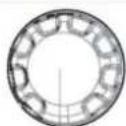
FONCTIONNEMENT
ACCESSOIRES ET OPTIONS
ACCESSOIRES
ACCESSOIRES OPTIONNELS INSTALLÉS SUR LE TERRAIN
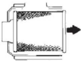
Rotate the filter while pulling straight out.
natural_image
Pure diagram of a cylindrical container with internal structure and arrow, no text or symbols presentnatural_image
Hand washing a circular object with a textured surface (no text or symbols)Outer edge of the outlet tube
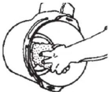
Wipe both sides of the outlet tube clean.
natural_image
Simple line drawing of a hand washing a circular object with a textured interior (no text or symbols)Inner edge of the outlet tube
natural_image
Illustration of a person holding a cylindrical object (no text or symbols visible)natural_image
Line drawing of a person holding a large cylindrical object (no text or symbols)natural_image
Pure diagram of a mechanical component with two arrows pointing outward (no text or symbols)text_image
Remove battery cover for oil change.MANIPULATION DE LA BATTERIE
! AVERTISSEMENT

text_image
FOR TRAILER MOUNTING PURPOSES, SEE DIMENSIONS BELOW: 59.50 28.86 1.25 Ø 0.62 DETAIL A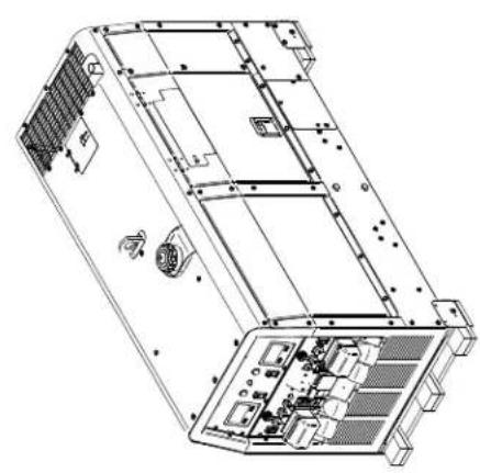
natural_image
Technical line drawing of an electronic device chassis showing internal components and mounting points (no text or labels)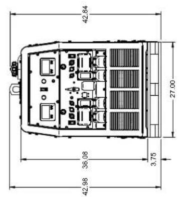
text_image
42.84 27.00 36.08 3.75 42.98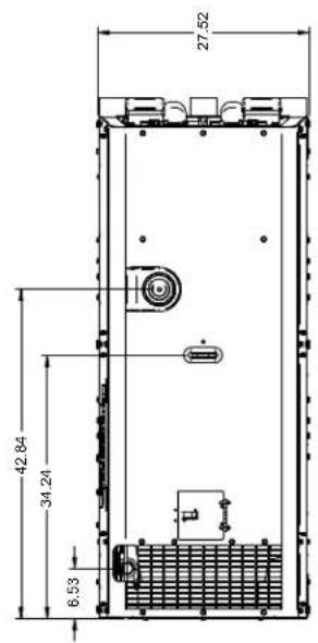
text_image
27.52 42.84 34.24 6.53