DCB119 - Battery charger DEWALT - Free user manual and instructions
Find the device manual for free DCB119 DEWALT in PDF.

User questions about DCB119 DEWALT
0 question about this device. Answer the ones you know or ask your own.
Ask a new question about this device
Download the instructions for your Battery charger in PDF format for free! Find your manual DCB119 - DEWALT and take your electronic device back in hand. On this page are published all the documents necessary for the use of your device. DCB119 by DEWALT.
USER MANUAL DCB119 DEWALT
If you have questions or comments, contact us.
IF YOU HAVE ANY QUESTIONS OR COMMENTS ABOUT THIS OR ANY DEWALT TOOL, CALL US TOLL FREE AT: 1-800-4-DEWALT (1-800-433-9258).

WARNING! Read and understand all instructions. Failure to follow all instructions listed below may result in electric shock, fire and/or serious personal injury.
SAVE THESE INSTRUCTIONS
Safety Instructions for Lasers
- Do not operate the laser in explosive atmospheres, such as in the presence of flammable liquids, gases, or dust. Power tools create sparks which may ignite the dust or fumes.
- Use the laser only with the specifically designated batteries. Use of any other batteries may create a risk of fire.
- Store idle laser out of reach of children and other untrained persons. Lasers are dangerous in the hands of untrained users.
- Use only accessories that are recommended by the manufacturer for your model. Accessories that may be suitable for one laser, may create a risk of injury when used on another laser.
- Tool service MUST be performed only by qualified repair personnel. Repairs, service or maintenance performed by unqualified personnel may result in injury. To locate your nearest DEWALT service center call 1-800-4-DEWALT (1-800-433-9258) or go to http://www.dewalt.com on the Internet.
- Do not use optical tools such as a telescope or transit to view the laser beam. Serious eye injury could result.
-
Do not place the laser in a position which may cause anyone to intentionally or unintentionally stare into the laser beam. Serious eye injury could result.
-
Do not position the laser near a reflective surface which may reflect the laser beam toward anyone's eyes. Serious eye injury could result.
- Turn the laser off when it is not in use. Leaving the laser on increases the risk of staring into the laser beam.
- Do not operate the laser around children or allow children to operate the laser. Serious eye injury may result.
- Do not remove or deface warning labels. If labels are removed user or others may inadvertently expose themselves to radiation.
- Position the laser securely on a level surface. Damage to the laser or serious injury could result if the laser falls.
- Dress properly. Do not wear loose clothing or jewelry. Contain long hair. Keep your hair, clothing, and gloves away from moving parts. Loose clothing, jewelry, or long hair can be caught in moving parts. Air vents often cover moving parts and should also be avoided.
⚠ WARNING: Use of controls or adjustments or performance of procedures other than those specified herein may result in hazardous radiation exposure.
WARNING! DO NOT DISASSEMBLE THE ROTARY LASER. There are no user serviceable parts inside. Disassembling the rotary laser will void all warranties on the product. Do not modify the product in any way. Modifying the tool may result in hazardous laser radiation exposure.
- The label on your tool may include the following symbols.
V .....volts nm .....wavelength in nanometers mW .....milliwatts IIIa .....Class IIIa Laser
* .....laser warning symbol

text_image
CLASS B: LAYER PROJECT DANGER LAYER REFLECTIVE AVOID SHORT COLD CONNECT 1000 METER EFFECT FINGER 2000 METER DIFF FINGER REFLECTIVE DELEGE, ENTRATE LA EXPRESSION RATIO DE LEA DAJAM EXPENDENCE TO LAUD, ENTRATE EXPENDENCE DIFF OUT. THIS PRODUET COMPLES WITH THE APPLENSIBLE REQUIREMENTS OF 2 LEMON PARTS 3400 TO 500 3400 TO 500 3400 TO 500 TO AVOID DIRECT EYE EXPENSES SEE STANDARD MODE WHEN WARNING ROLLAR. PARA ENTRAT LA EXPESICION DIRECTA DE LOS OLIVOS, UTRACE EL MISO EN SUPERAL VISUALIZAZA LA SURBLUA. POUR EVTER TOUTE EXPOSITION DIRECTA VASIL VIDE, UTILIS LE MODE CTATTENTS, POUR VISUALIZAR LA BULLE.
text_image
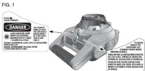
DW074 ROTARY LASER WARNING: THE RISK OF PLANTY. VOLT WHO READ AND UNDERSTAND INSTRUCTION MANUAL. ADVERTENCIA: PARA EL MANSUS SUEBOS EL EL MANSUS DE INSTRUCIO COMES. AVERTISSEMENT: A TINIC PENDANTUO LIKE LE SAAGLE. DANGER RADATING LAYER DE LAURA LEVERA BAUTRIGO, ME FOR USA FOR LANSUS REPROVATION, FLOR OR AVANT www.dw074.com PENIERO LASER UNITS PELIGRO LASER UNITS RADATING LANSUS DATA TRANSMID. NO FEET VS. VISUE EN EL HAZ. DANGER RADATING LASER DE LONGOUT DANCE, ME FOR USA IS FABRICAN.- For your convenience and safety, the following labels are on your laser (Fig. 1).
AVOID EXPOSURE: LASER RADIATION IS EMITTED FROM THIS APERTURES.
DANGER: LASER RADIATION. AVOID DIRECT EYE EXPOSURE.
Laser Information
The DW074 Cordless Rotary Laser is listed as a CLASS IIIA LASER PRODUCT and complies with the applicable requirement of title 21 of the Code of Federal Regulations set forth by: the Department of Health, Education, and Welfare; the Food and Drug Administration; the Center for Devices and Radiological Health.
These devices comply with Part 15 of the FCC Rules. Operation is subject to the following two conditions: (1) this device may not cause harmful interference, and (2) this device must accept any interference received, including interference that may cause undesired operation.
NOTE: This equipment has been tested and found to comply with the limits for a Class B digital device, pursuant to Part 15 of the FCC Rules. These limits are designed to provide reasonable protection against harmful interference in a residential installation. This equipment generates, uses and can radiate radio frequency energy and, if not installed and used in accordance with the instructions, may cause harmful interference to radio communications. However, there is no guarantee that interference will not occur in a particular installation. If this equipment does cause harmful interference to radio and television reception, which can be determined by turning the equipment off and on, the user is encouraged to try to correct the interference by one or more of the following measures:
- Reorient or relocate the receiving antenna.
-
Increase the separation between the equipment and receiver.
-
Connect the equipment into an outlet on a circuit different from that which the receiver is connected.
- Consult the dealer or an experienced radio/TV technician for help.
These Class B digital devices comply with Canadian ICES-003.
| SPECIFICATIONS | |
| Light Source Semiconductor laser diode | |
| Laser Wavelength 630 | -680 nm Visible |
| Laser Power <5mw, CLASS IIIa LASER PRODUCT | |
| Rotation Speed 0 – 600 rpm | |
| Self-Leveling Range ± 5° | |
| Indoor Visible Range 200' (61 m) diameter | |
| Range with Detector 1500' (450 m) diameter | |
| Level Accuracy ± 1/4" per 100' ( ± 2 mm per 10 m) | |
| Power Source 2 D-cell batteries | |
| Operating Temperature | 23°F to 122°F (-5°C to 50°C) |
| Storage Temperature | -4°F to 158°F (-20°C to 70°C) |
| Environmental | Water resistant |
Important Safety Instructions for Batteries
AWARNING: Batteries can explode, or leak, and can cause injury or fire. To reduce this risk:
- Carefully follow all instructions and warnings on the battery label and package.
- Always insert batteries correctly with regard to polarity (+ and -), marked on the battery and the equipment.
- Do not short battery terminals.
- Do not charge batteries.
-
Do not mix old and new batteries. Replace all of them at the same time with new batteries of the same brand and type.
-
Remove dead batteries immediately and dispose of per local codes.
- Do not dispose of batteries in fire.
- Keep batteries out of reach of children.
- Remove batteries if the device will not be used for several months.
SAVE THESE INSTRUCTIONS FOR FUTURE USE
LASER OPERATION
• To extend battery life, turn the laser off when it is not in use.
- To ensure the accuracy of your work, check the laser calibration often. Refer to Field Calibration Check under Laser Maintenance.
- Before attempting to use the laser, make sure the tool is positioned on a relatively smooth, secure surface.
- Always mark the center of the laser line or dot. If you mark different parts of the beam at different times you will introduce error into your measurements.
- To increase working distance and accuracy, set up the laser in the middle of your working area.
- When attaching to a tripod or wall, mount the laser securely.
- When working indoors, a slow rotary head speed will produce a visibly brighter line, a faster rotary head speed will produce a visibly solid line.
- To increase beam visibility, wear Laser Enhancement Glasses and/or use a Laser Target Card to help find the beam.
- Extreme temperature changes can cause movement or shifting of building structures, metal tripods, equipment, etc., which can effect accuracy. Check your accuracy often while working.
- When working with the DEWALT Digital Laser Detector, set the laser's rotation speed to the fastest setting.
- If the laser is dropped or has suffers a sharp blow, have the calibration system checked by a qualified service center before using the laser.
text_image
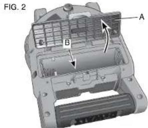
FIG. 2 A B CInstalling and Removing the Batteries (Fig. 2)
NOTE: This tool is powered by two D-cell batteries.
INSTALLING THE BATTERY PACK
- Lift up the battery compartment cover (A) as shown in Figure 1.
- Insert two fresh D-cell batteries in the compartment, placing the batteries according to embossed icon (B) on the inside of the compartment.
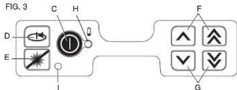
Laser Control Panel
The laser is controlled by the power button (C), the speed/rotation button (D) and the standby button (E). The four arrow buttons
(F, G) are used to adjust the bubble vial in vertical mode. The two LED indicator lights are used to indicate power/low battery (H) and standby mode (I).
Powering On
Be sure that the batteries are properly installed and the battery door is securely closed.
CAUTION: The laser will operate even if battery door is not fully latched. To secure the batteries, always ensure battery door is closed and latched.
text_image
FIG. 3 C H D E I F GTURNING THE LASER ON IN HORIZONTAL MODE (SELF-LEVELING) (FIG. 3)
- Gently press the power button (C) to power the laser on. The power LED indicator light (H) will illuminate.
- The unit will automatically self-level.
- When the unit is finished leveling, the laser beam will turn on and the rotor will operate at the most recent speed setting.
- Press the speed/rotation button (D) to select a different rotation speed if desired.
NOTE: The power LED indicator light (H) is used to indicate on (steady) and low battery (flashing).
NOTE: The head will begin or resume rotation once the laser is level.
TURNING THE LASER ON IN VERTICAL MODE (MANUAL LEVELING)
- Gently press the power button (C) to power the laser on. The power LED indicator light (H) will illuminate and the Standby Mode LED (I) will begin to flash.
NOTE: The unit automatically enters Standby Mode when put in Vertical Mode.
- Manually level the unit using the four arrow buttons (F, G).
- Gently press the standby button (E) or speed/rotation button (D) to disengage Standby Mode.
- Press the speed/rotation button (D) to select the desired rotation speed.
LEVELING THE LASER IN VERTICAL MODE
- Gently press the standby button (E) to engage Standby Mode. ▲CAUTION: To reduce the risk of direct eye exposure to the laser beam, always engage Standby Mode before viewing the bubble vial.
- View the position of the bubble vial by sighting straight down from above the unit.
NOTE: Viewing the bubble from any angle other than straight down will result in an inaccurate reading.
- Center the bubble exactly midpoint between the hatchmarks on the vial. The bubble is adjusted by pressing the up and down arrow buttons (F, G). The single arrow buttons move the bubble slowly; the double arrow buttons allow fast adjustment of the bubble.
- Gently press the standby button (E) or speed/rotation button (D) to disengage Standby Mode.
TURNING THE LASER OFF
Gently press the power button (C) to turn the laser off. The power LED indicator light (H) will no longer be illuminated.
Laser Control Panel Buttons
POWER BUTTON
Press the power button (H) to power the unit on and off.
ARROW BUTTONS
The arrow buttons (F, G) are used to adjust/level the bubble in the vial. The single arrow buttons (F) move the bubble slowly; the double arrow buttons (G) allow fast adjustment of the bubble.
SPEED/ROTATION BUTTON
The speed/rotation button (D) is used to adjust the rotation speed of the laser beam through its 3 preset speeds.
The head speed will cycle through 3 speeds, then repeat the sequence as the speed/rotation button is pressed.
REMEMBER:
Slow speed = Bright Beam Fast Speed = Solid Beam
STANDBY BUTTON
Press the standby button (E) to engage Standby Mode. This turns off the laser beam and stops the laser head from rotating. The standby LED indicator light (I) will flash when the unit is in Standby Mode.
NOTE: Pressing any of the arrow buttons (F, G) will also engage Standby Mode.
⚠️CAUTION: To reduce the risk of direct eye exposure to the laser beam, always engage Standby Mode before viewing the bubble vial.
LOW BATTERY INDICATION
When the batteries approach end of life, the power LED indicator light (H) will begin to flash. When this signal is observed, only a short period of runtime is left before the unit will completely shut down. The batteries should be replaced with new batteries as soon as possible.
Using the Laser on a Tripod
- Position the tripod securely and set it to the desired height.
- Make sure that the top of the tripod is roughly level. The laser will self-level only if the top of the tripod is within ±5' of level. If the laser is set up too far out of level, it will beep when it reaches the limit of its leveling range. No damage will be done to the laser, but it will not operate in an "out of level" condition.
- Secure the laser to the tripod by screwing the threaded knob on the tripod into the female thread on the bottom of the laser. NOTE: Be sure that the tripod you are working with has a 5/8"-11 threaded screw to ensure secure mounting.
- Turn the laser on and adjust the rotation speed and controls as desired.
FIG. 4
natural_image
Close-up of a Siemens PLUMB mode dial with no visible text or symbols on the device itself.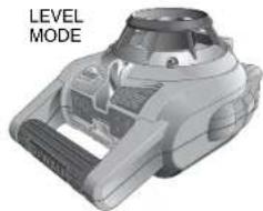
natural_image
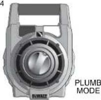
3D rendered mechanical component with no visible text or symbolsUsing the Laser on a Floor (Fig. 4)
The laser level can be positioned directly on the floor for leveling and plumbing applications such as framing walls.
- Place the laser on a relatively smooth and level surface where it will not be disturbed.
- Position the laser for a level or plumb setting as shown.
- Turn the laser on and adjust the rotation speed and controls as desired.
NOTE: The laser will be easier to set up for wall applications if the rotation speed is set to 0 rpms and if the remote control is used to line up the laser with control marks. The remote allows one person to set up the laser.
Manual Head Rotation
The laser is designed with a protective roll cage around the rotary head to prevent accidental damage from work site activities. You can still access the rotary head and manually direct the beam to establish or transfer a mark.
Laser Accessories
Recommended accessories for use with your tool are available for purchase at your factory-owned local service center.
▲WARNING: Since accessories, other than those offered by DEWALT, have not been tested with this product, use of such accessories with this tool could be hazardous. To reduce the risk of injury, only DEWALT, recommended accessories should be used with this product.
If you need assistance in locating any accessory, please contact DEWALT Industrial Tool Co., 701 East Joppa Road, Baltimore, MD 21286, call 1-800-4-DEWALT (1-800-433-9258) or visit our website www.dewalt.com.
Laser Enhancement Glasses
Some laser kits include a pair of Laser En hancement Glasses (Fig. 5). These red lens glasses improve the visibility of the laser beam under bright light conditions or over long distances when the laser is used for interior applications. These glasses are not required to operate the laser.
FIG. 5
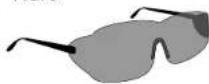
CAUTION: These glasses are not ANSI approved safety glasses and should not be worn while operating other tools. These glasses do not keep the laser beam from entering your eyes.
▲DANGER: TO REDUCE THE RISK OF SERIOUS PERSONAL INJURY, NEVER STARE DIRECTLY INTO THE LASER BEAM, WITH OR WITHOUT THESE GLASSES.
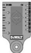
Target Card
Some laser kits include a Laser Target Card (Fig. 6) to aid in locating and marking the laser beam. The target card enhances the visibility of the laser beam as the beam crosses over the card. The card is marked with standard and metric scales. The laser beam passes through the red plastic and reflects off of the reflective tape on the reverse side. The magnet at the top of the card is designed to hold the target card to ceiling track or steel studs to determine plumb and level positions. For best performance when using the Target Card, the DEWALT logo should be facing you
FIG. 6
Digital Laser Detector: DW0742
(Fig. 7, 8)
Some laser kits include a DEWALT Digital Laser Detector. The DEWALT Digital Laser Detector allows you to locate a laser beam emitted by a rotary laser in bright light conditions or over long distances. The detector can be used in both indoor and outdoor situations where it is difficult to see the laser beam.
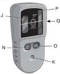
The detector is not for use with non-rotating lasers but is compatible with most rotary red-beam or infrared (invisible) beam lasers on the market. The detector gives both visual signals through the display window (J) and audio signals through the speaker (K) to indicate the location of the laser beam.
The DEWALT Digital Laser Detector can be used with or without the detector clamp. When used with the clamp, the detector can be positioned on a grade rod, leveling pole, stud or post.
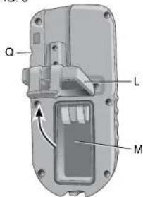
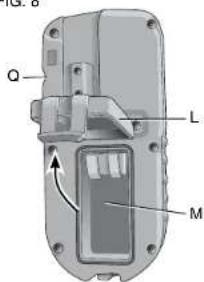
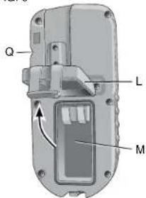
BATTERIES (FIG. 7)
The digital laser detector is powered by a 9-volt battery. To install the battery provided, lift up on the battery compartment cover (L). Place the
FIG. 7
text_image
J P Q N O KFIG. 8
text_image
Q L M9-volt battery in the compartment, aligning the battery as shown on the embossed icon (M).
DETECTOR CONTROLS (FIG. 8)
The detector is controlled by the power button (N) and the volume button (O).
When the power button is pushed once, the detector is turned on. The top of the display window shows the ON icon and the volume icon.
The DEWALT Digital Laser Detector also has an auto shut-off feature. If a rotary laser beam does not strike the beam detection window, or if no buttons are pressed, the detector will shut itself off in about 15 minutes.
To turn off the audible signal push the button a third time; the volume icon will disappear.
Detector Operation (Fig. 9)
- Set up and position the rotary laser that you will be using according to the manufacturer's directions. Turn the laser on and make sure that the laser is rotating and emitting a laser beam.
NOTE: This detector has been designed to be used only with a rotating laser. The detector will not work with a stationary beam laser level.
- Turn the detector on by pressing the power button (N).
- Adjust the volume as desired as described in the Detector Controls.
- Position the detector so that the detector window (P) is facing the laser beam produced by the rotary laser. Move the detector up or down within the approximate area of the beam, until you have centered the detector. For information about the display window indicators and the audible signal indicators, refer to the table titled Indicators (Fig. 9).
FIG. 9
INDICATORS
| Above Grade | Slightly Above Grade | On Grade | Slightly below Grade | below Grade | |
| [ZX02] | fast beep | fast beep steady tone | slow beep slow beep | ||
 |  |  |  | 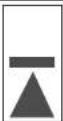 |  |
- Use the marking notches (Q) to accurately mark the position of the laser beam.
FIG. 10
text_image
G. 10 V T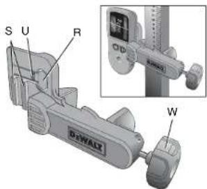
text_image
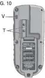
S U R DcWALX WMOUNTING ON A GRADE ROD (FIG. 10)
- To secure your detector to a grade rod, first attach the detector to the clamp by pushing in on the clamp latch (R). Slide the tracks (S) on the clamp around the rail (T) on the detector until the latch (U) on the clamp pops into the latch hole (V) on the detector.
- Open the jaws of the clamp by turning the clamp knob (W) counterclockwise.
- Position the detector at the height needed and turn the clamp knob clockwise to secure the clamp on the rod.
- To make adjustments in height, slightly loosen the clamp, reposition and retighten.
Detector Cleaning and Storage
- Dirt and grease may be removed from the exterior of the detector using a cloth or soft, non-metallic brush.
- The ☐WALT digital laser detector is rain resistant but not immersible. Do not pour water on the unit or submerge it under water.
- The best storage place is one that is cool and dry—away from direct sunlight and excess heat or cold.
Detector Service
Except for batteries, there are no user serviceable parts in the Digital Laser Detector. Do not disassemble the unit. Unauth orized tampering with the laser detector will void all warranties.
Detector Troubleshooting
THE DETECTOR WILL NOT TURN ON.
- Press and release the power button.
- Check to see that the battery is in place and in the proper position.
- If the detector is very cold, allow it to warm up in a heated area.
- Replace the 9-volt battery. Turn the unit on.
- If the detector still does not turn on, take the detector to a DEWALT service center.
THE DETECTOR'S SPEAKER MAKES NO SOUND.
- Ensure that the detector is on.
- Press the volume button. It will toggle from high, to low, to mute.
- Ensure that the rotary laser is spinning and that it is emitting a laser beam.
- If the detector is still not making any sound, take it to a D EWALT service center.
THE DETECTOR DOES NOT RESPOND TO A STATIONARY LASER BEAM.
- The BWALT Digital Laser Detector has been designed to work only with rotary lasers.
THE DETECTOR GIVES OFF A TONE BUT THE LCD DISPLAY WINDOW DOES NOT FUNCTION.
- If the detector is very cold, allow it to warm up in a heated area.
- If the LCD display window is still not functioning, take the detector to a DEWALT service center.
Construction Grade Rod
▲DANGER: NEVER attempt to use a grade rod in a storm or near overhanging electric wires. Death or serious personal injury will occur.
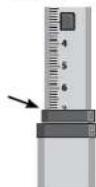
Some laser kits include a grade rod. The DEWALT Grade Rod is marked with measurement scales on both sides and is constructed
in telescoping sections. A spring-loaded button actuates a lock to hold the grade rod at various lengths.
The front of the grade rod has the measurement scale starting at the bottom. Use this for measuring from the ground up when grading or leveling jobs.
The back of the grade rod is designed to measure the height of ceilings, joists, etc. Fully extend the top section of the grade rod until the button locks into the previous section. Extend that section
either until it locks into the adjacent section or until the grade rod touches the ceiling or joist. The height is read where the last extended section exits the previous lower section, as shown in Figure 11.
FIG. 11
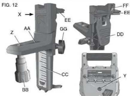
Using the Laser with a Wall Mount (Fig. 12)
Some laser kits include a Wall Mount. It can be used for attaching the tool to track or ceiling angle and to aid in acoustical ceiling installation. Follow the directions below for using the wall mount.
CAUTION: Before attaching the laser level to wall track or ceiling angle, be sure that the track or angle is properly secured.
- Place the laser on the mounting base (X) aligning the hole (Y) on the bottom of the laser with the hole (Z) in the mounting base. Place rear rubber foot into the mounting base slot (AA). Turn the mounting knob (BB) to secure the laser.
- With the wall mount measuring scale (CC) facing you, push the clamp lever (DD) in to open the clamp jaws (EE).
- Position the clamp jaws (EE) around the wall track or ceiling angle and release the clamp lever (DD) to close the clamp
jaws on the track. Be sure that the wall mount is secure before proceeding.
CAUTION: Always use a ceiling wire hanger or equivalent material, in addition to the wall mount clamp locking knob, to help secure the laser level while mounting it to a wall. Thread the wire through the handle of the laser level. DO NOT thread the wire through the protective roll cage. Additionally, screws may be used to fasten the wall mount directly to the wall as a back up. A screw holes (FF) is located at the top of the wall mount.
text_image
FIG. 12 X → Z AA EE GG CC BB DD FF EE Y-
The tool can be adjusted up and down to the desired offset height for working. To change the height, loosen the locking knob (GG) located on the side of the wall mount to move the laser level up and down to the desired height. Support the mounting base when adjusting the height.
-
Use the wall mount measuring scale (CC) to pinpoint your mark.
NOTE: It may be helpful to turn the power on and turn the rotary head so that it puts a dot on one of the laser scales. The DEWALT target card is marked at 1-1/2" (38 mm), therefore, it may be easiest to set the offset of the laser to 1-1/2" (38 mm) below the track.
- Once you have positioned the laser at the desired height, tighten the locking knob (GG) to maintain this position.
LASER MAINTENANCE
- Under some conditions, the glass lens inside the rotary head may collect some dirt or debris. This will affect beam quality and operating range. The lens should be cleaned with a cotton swab moistened with water as shown in Figure 13.
- The flexible rubber shield can be cleaned with a wet lint-free cloth such as a cotton cloth. USE WATER ONLY — DO NOT use cleansers or solvents. Allow the unit to air dry before storing.
• To maintain the accuracy of your work, check the calibration of the laser often. Refer to Field Calibration Check.
- Calibration checks and other maintenance repairs can be performed by DEWALT service centers. Two free calibration checks are included under the DEWALT One Year Free Service Contract.
- When the laser is not in use, store it in the kit box provided.
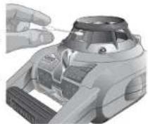
FIG. 13
- Do not store your laser in the kit box if the laser is wet. Dry exterior parts with a soft, dry cloth and allow the laser to air dry.
- Do not store your laser at temperatures below 0°F (-18°C) or above 105°F (41°C).
⚠ WARNING: Never use solvents or other harsh chemicals for cleaning the non-metallic parts of the tool. These chemicals may weaken the materials used in these parts. Use a cloth dampened only with water and mild soap. Never let any liquid get inside the unit; never immerse any part of the unit into a liquid. Never use compressed air to clean the laser.
Field Calibration Check (Fig. 14-16)
Field calibration checks should be done frequently. This section provides instructions for performing simple field calibration checks of your DEWALT Rotary Laser. Field calibration checks do not calibrate the laser. That is, these checks do not correct errors in the leveling or plumbing capability of the laser. Instead, the checks indicate whether or not the laser is providing a correct level and plumb line. These checks cannot take the place of professional calibration performed by a DEWALT service center.
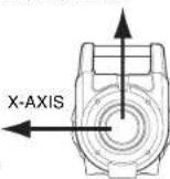
LEVEL CALIBRATION CHECK (X-AXIS)
FIG. 14 Y-AXIS
-
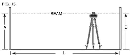
Set up a tripod between two walls that are at least 50 feet (15.3 m) apart. The exact location of the tripod is not critical.
-
Mount the laser unit on the tripod so that the X-axis points directly toward one of the walls.
-
Turn the laser unit on and allow it to self-level.
-
Mark and measure points A and B on the walls as shown in Figure 15.
text_image
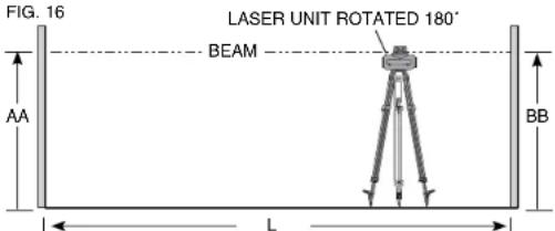
FIG. 15 BEAM A B L- Turn the entire laser unit 180° so the X-axis points directly toward the opposite wall.
- Allow the laser unit to self-level, and mark and measure points AA and BB on the walls as shown in Figure 16.
text_image
FIG. 16 LASER UNIT ROTATED 180° BEAM AA L BB- Calculate the total error using the equation:
Total Error = (AA - A) - (BB - B)
- Compare total error to the allowable limits shown in the following table.
| Distance between walls | Allowable Error |
| L = 50 ft. (15.3 m) 1/4" | (6 mm) |
| L = 75 ft. (22.9 m) 3/8" | (9 mm) |
| L = 100 ft. (30.5 m) 1/2" | (12 mm) |
LEVEL CALIBRATION CHECK (Y-AXIS)
Repeat the procedure above, but with the laser unit positioned so the Y-axis is pointed directly toward the walls.
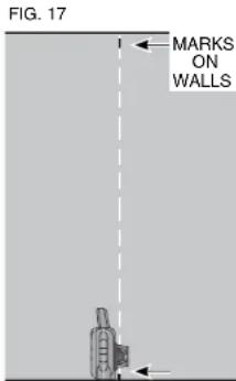
PLUMB ERROR CHECK (FIG. 17)
- Using a standard plumb bob as a reference, mark the top and bottom of a wall (Be sure to mark the wall and not the floor and ceiling.)
- Position the rotary laser securely on the floor approximately 1 m (3 ft.) from the wall.
- Turn the laser on and level it using the arrow buttons to center the bubble. Put the unit in low speed rotation for maximum visibility, making sure the beam passes through the mark on the bottom of the wall. Recheck the bubble position to confirm it is still centered.
- If the center of the beam lines up with the marks at the bottom and top of the wall, the laser is properly calibrated.
NOTE: This check should be done with a wall no shorter than the allest wall for which this laser will be used.
text_image
FIG. 17 MARKS ON WALLSRepairs
To assure product SAFETY and RELIABILITY, repairs, maintenance and adjustments should be performed by a DEWALT factory service center, a DEWALT authorized service center or other qualified service personnel. Always use identical replacement parts.
Three Year Limited Warranty
DEWALT will repair, without charge, any defects due to faulty materials or workmanship for three years from the date of purchase. This warranty does not cover part failure due to normal wear or tool abuse. For further detail of warranty coverage and warranty repair information, visit www.dewalt.com or call 1-800-4-DEWALT (1-800-433-9258). This warranty does not apply to accessories or damage caused where repairs have been made or attempted by others. This warranty gives you specific legal rights and you may have other rights which vary in certain states or provinces.
In addition to the warranty, DEWALT tools are covered by our:
1 YEAR FREE SERVICE
DEWALT will maintain the tool and replace worn parts caused by normal use, for free, any time during the first year after purchase.
90 DAY MONEY BACK GUARANTEE
If you are not completely satisfied with the performance of your DEWALT Power Tool, Laser, or Nailer for any reason, you can return it within 90 days from the date of purchase with a receipt for a full refund – no questions asked.
LATIN AMERICA: This warranty does not apply to products sold in Latin America. For products sold in Latin America, see country specific warranty information contained either in the packaging, call the local company or see website for warranty information.
FREE WARNING LABEL REPLACEMENT: If your warning labels (Fig. 1) become illegible or are missing, call 1-800-4-DEWALT for a free replacement.
POUR TOUTE QUESTION OU COMMENTAIRE RELATIF À CET OUTIL OU TOUT AUTRE OUTIL DEWALT, COMPOSEZ GRATUITEMENT LE : 1-800-4-DEWALT (1-800-433-9258).
text_image
FIG. 3 C H D E I F GMISE EN MARCHE DU LASER EN MODE HORIZONTAL (AUTO-NIVELAGE) (FIG. 3)
text_image
J P Q N O KFIG. 8
text_image
Q L Mtext_image
FIG. 10 V T S U R W DWALYINSTALLATION SUR UNE TIGE GRADUÉE (FIG. 10)
text_image
FIG. 12 X → Z AA EE GG CC BB FF EE DD Ynatural_image
3D mechanical component diagram showing internal structure with labeled parts A and B (no text or symbols beyond labels)text_image
FIG. 3 C H D E I F Gtext_image
J P Q N O KFIG. 8
text_image
Q L Mtext_image
G. 10 V T S U R CTD W DEWALTMONTAJE SOBRE UNA VARA GRADUADA. (FIG. 10)
text_image
FIG. 12 X → Z AA GG CC BB EE DD FF EE YLocal D, Col. Obrera (55) 5588 9377
MERIDA, YUC
Calle 63 #459-A - Col. Centro (999) 928 5038
MONTERREY, N.L.
Av. Francisco I. Madero 831 Poniente - Col. Centro (818) 375 23 13
PUEBLA. PUE
17 Norte #205 - Col. Centro (222) 246 3714
QUERETARO, QRO
Av. San Roque 274 - Col. San Gregorio (442) 2 17 63 14
SAN LUIS POTOSI, SLP
3,0 = -¥ 0 - 600Crpm
SOLAMENTE PARA PROPÓSITO DE MÉXICO:
IMPORTADO POR: DEWALT S.A. DE C.V.
BOSQUES DE CIDROS, ACCESO RADIATAS NO.42
DEWALT Industrial Tool Co., 701 East Joppa Road, Baltimore, MD 21286 (FEB08) Part No. 648768-00 DW074 Copyright © 2008 DEWALT The following are trademarks for one or more DEWALT power tools: the yellow and black color scheme; the "D" shaped air intake grill; the array of pyramids on the handgrip; the kit box configuration; and the array of lozenge-shaped humps on the surface of the tool.