DCB117 - Battery charger DEWALT - Free user manual and instructions
Find the device manual for free DCB117 DEWALT in PDF.

User questions about DCB117 DEWALT
0 question about this device. Answer the ones you know or ask your own.
Ask a new question about this device
Download the instructions for your Battery charger in PDF format for free! Find your manual DCB117 - DEWALT and take your electronic device back in hand. On this page are published all the documents necessary for the use of your device. DCB117 by DEWALT.
USER MANUAL DCB117 DEWALT
Before returning this product call
1-800-4-DEWALT
IF YOU SHOULD EXPERIENCE A PROBLEM WITH YOUR DEWALT PURCHASE,
CALL 1-800-4-DEWALT
IN MOST CASES, A DEWALT REPRESENTATIVE CAN RESOLVE YOUR PROBLEM OVER THE PHONE.
IF YOU HAVE A SUGGESTION OR COMMENT, GIVE US A CALL. YOUR FEEDBACK IS VITAL TO THE SUCCESS OF DEWALT'S QUALITY IMPROVEMENT PROGRAM.
Questions? Visit us at www.dewalt.com
16 Gauge Cordless Nailer
text_image
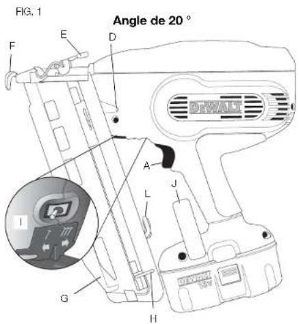
FIG. 1 Angled 20° DEWALF A L J G H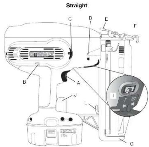
text_image
Straight C D E F B A J L G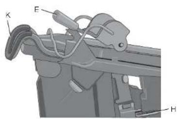
text_image
Technical diagram of a mechanical device with labeled parts K, E, and H| TOOL SPECIFICATIONS | ||
| DC616 DC618 | ||
| Firing Mode | Selective | Selective |
| Voltage | 18 | 18 |
| Height | 12" (305 mm) | 12.4" (315 mm) |
| Width | 4.18" (106 mm) | 4.18" (106 mm) |
| Length 12.75" (324 mm) | 12.5" (317 mm) | |
| Weight | .5lbs. (3.8 kg) | 8.5lbs (3.8 kg) |
| Magazine Angle | Straight | Angled 20° |
| Loading Capacity | Up to 110 Nails | Up to 120 Nails |
A. Trigger
B. Contact trip lock-off
C. Depth adjustment
wheel
D. Headlights/Low
battery indicator
E. Jam clearing latch
F. Contact trip
G. Magazine
H. Pusher
1. Bump/sequential
selector switch
J. Reversible suspension
hook
K. No-mar pad
L. No-mar tip storage

| NAIL SPECIFICATIONS | ||
| Nail Lengths Angled | -1/4", 1-1/2", 1-3/4", 2", 2-1/2"(32 mm, 38 mm, 44 mm, 51 mm, 65 mm) | Straight1-1/4", 1-1/2", 1-3/4", 2", 2-1/2"(32 mm, 38 mm, 44 mm, 51 mm, 65 mm) |
| Shank Diameters | 16 gauge 16 gauge | |
| Nail Stick Angles | 20° 0° | |
Definitions: Safety Guidelines
The definitions below describe the level of severity for each signal word. Please read the manual and pay attention to these symbols.
▲DANGER: Indicates an imminently hazardous situation which, if not avoided, will result in death or serious injury.
A WARNING: Indicates a potentially hazardous situation which, if not avoided, could result in death or serious injury.
▲CAUTION: Indicates a potentially hazardous situation which, if not avoided, may result in minor or moderate injury.
NOTICE: Indicates a practice not related to personal injury which, if not avoided, may result in property damage.
IF YOU HAVE ANY QUESTIONS OR COMMENTS ABOUT THIS OR ANY DEWALT TOOL, CALL US TOLL FREE AT: 1-800-4-DEWALT (1-800-433-9258).

WARNING: To reduce the risk of injury, read the instruction manual.
General Power Tool Safety Warnings
WARNING! Read all safety warnings and all instructions. Failure to follow the warnings and instructions may result in electric shock, fire and/or serious injury.
SAVE ALL WARNINGS AND INSTRUCTIONS FOR FUTURE REFERENCE
The term "power tool" in the warnings refers to your mains-operated (corded) power tool or battery-operated (cordless) power tool,
1) WORK AREA SAFETY
a) Keep work area clean and well lit. Cluttered or dark areas invite accidents.
b) Do not operate power tools in explosive atmospheres, such as in the presence of flammable liquids, gases or dust. Power tools create sparks which may ignite the dust or fumes.
c) Keep children and bystanders away while operating a power tool. Distractions can cause you to lose control.
2) ELECTRICAL SAFETY
a) Power tool plugs must match the outlet. Never modify the plug in any way. Do not use any adapter plugs with earthed (grounded) power tools. Unmodified plugs and matching outlets will reduce risk of electric shock.
b) Avoid body contact with earthed or grounded surfaces such as pipes, radiators, ranges and refrigerators. There is an increased risk of electric shock if your body is earthed or grounded.
c) Do not expose power tools to rain or wet conditions. Water entering a power tool will increase the risk of electric shock.
d) Do not abuse the cord. Never use the cord for carrying, pulling or unplugging the power tool. Keep cord away from heat, oil, sharp edges or moving parts. Damaged or entangled cords increase the risk of electric shock.
e) When operating a power tool outdoors, use an extension cord suitable for outdoor use. Use of a cord suitable for outdoor use reduces the risk of electric shock.
i) If operating a power tool in a damp location is unavoidable, use a ground fault circuit interrupter (GFCI) protected supply. Use of a GFCI reduces the risk of electric shock.
3) PERSONAL SAFETY
a) Stay alert, watch what you are doing and use common sense when operating a power tool. Do not use a power tool while you are tired or under the influence of drugs, alcohol or medication. A moment of inattention while operating power tools may result in serious personal injury.
b) Use personal protective equipment. Always wear eye protection. Protective equipment such as dust mask, non-skid safety shoes, hard hat, or hearing protection used for appropriate conditions will reduce personal injuries.
c) Prevent unintentional starting. Ensure the switch is in the off position before connecting to power source and/or battery pack, picking up or carrying the tool. Carrying power tools with your finger on the switch or energizing power tools that have the switch on invites accidents.
d) Remove any adjusting key or wrench before turning the power tool on. A wrench or a key left attached to a rotating part of the power tool may result in personal injury.
e) Do not overreach. Keep proper footing and balance at all times. This enables better control of the power tool in unexpected situations.
1) Dress properly. Do not wear loose clothing or jewelry. Keep your hair, clothing and gloves away from moving parts. Loose clothes, jewelry or long hair can be caught in moving parts.
g) If devices are provided for the connection of dust extraction and collection facilities, ensure these are connected and properly used. Use of dust collection can reduce dust-related hazards.
4) POWER TOOL USE AND CARE
a) Do not force the power tool. Use the correct power tool for your application. The correct power tool will do the job better and safer at the rate for which it was designed.
b) Do not use the power tool if the switch does not turn it on and off. Any power tool that cannot be controlled with the switch is dangerous and must be repaired.
c) Disconnect the plug from the power source and/or the battery pack from the power tool before making any adjustments, changing accessories, or storing power tools. Such preventive safety measures reduce the risk of starting the power tool accidentally.
d) Store idle power tools out of the reach of children and do not allow persons unfamiliar with the power tool or these instructions to operate the power tool. Power tools are dangerous in the hands of untrained users.
c) Maintain power tools. Check for misalignment or binding of moving parts, breakage of parts and any other condition that may affect the power tool's operation. If damaged, have the power tool repaired before use. Many accidents are caused by poorly maintained power tools.
1) Keep cutting tools sharp and clean. Properly maintained cutting tools with sharp cutting edges are less likely to bind and are easier to control.
g) Use the power tool, accessories and tool bits, etc. in accordance with these instructions, taking into account the working conditions and the work to be performed. Use of the power tool for operations different from those intended could result in a hazardous situation.
5) BATTERY TOOL USE AND CARE
a) Recharge only with the charger specified by the manufacturer. A charger that is suitable for one type of battery pack may create a risk of fire when used with another battery pack.
b) Use power tools only with specifically designated battery packs. Use of any other battery packs may create a risk of injury and fire.
c) When battery pack is not in use, keep it away from other metal objects, like paper clips, coins, keys, nails, screws, or other small metal objects, that can make a connection from one terminal to another. Shorting the battery terminals together may cause burns or a fire.
d) Under abusive conditions, liquid may be ejected from the battery; avoid contact. If contact accidentally occurs, flush with water. If liquid contacts eyes, additionally seek medical help. Liquid ejected from the battery may cause irritation or burns.
6) SERVICE
a) Have your power tool serviced by a qualified repair person using only identical replacement parts. This will ensure that the safety of the power tool is maintained.
Nailer Safety Warnings
- Always assume that the tool contains fasteners. Careless handling of the nailer can result in unexpected firing of fasteners and personal injury.
- Do not point the tool towards yourself or anyone nearby. Unexpected triggering will discharge a fastener causing an injury.
- Do not actuate the tool unless the tool is placed firmly against the workpiece. If the tool is not in contact with the workpiece, the fastener may be deflected away from your target.
- Disconnect the tool from the power source when the fastener jams in the tool. While removing a jammed fastener, the tacker may be accidentally activated if it is plugged in.
- Use caution while removing a jammed fastener. The mechanism may be under compression and the fastener may be forcefully discharged while attempting to free a jammed condition.
- Do not use this nailer for fastening electrical cables. It is not designed for electric cable installation and may damage the insulation of electric cables thereby causing electric shock or fire hazards.
Additional Nailer Safety Warnings
WARNING: When using any nailer, all safety precautions, as outlined below, should be followed to avoid the risk of death or serious injury. Read and understand all instructions before operating the tool.
- Hold tool by insulated gripping surfaces when performing an operation where the cutting tool may contact hidden wiring. Contact with a "live" wire will make exposed metal parts of the tool "live" and shock the operator.
- Actuating tool may result in flying debris, collation material, or dust which could harm operator's eyes. The operator and all those persons in the general area should wear safety glasses with permanently attached side shields. Approved safety glasses are imprinted with the characters "Z87.1". It is the employer's responsibility to enforce the use of eye protection equipment by the tool operator and other people in the work area. (Fig. A)
• Always wear appropriate personal hearing and other protection during use. Under some conditions and duration of use, noise from this product may contribute to hearing loss. (Fig. A)
FIG.A

FIG. B

ПО. С
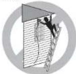
FIG. D
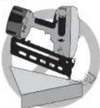
FIG. E
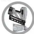
FIG. F
- Disconnect battery pack from the tool when not in use. Always remove battery pack and remove fasteners from magazine before leaving the area or passing the tool to another operator. Do not carry tool to another work area in which changing location involves the use of scaffoldings, stairs, ladders, and the like, with battery pack connected. Do not make adjustments, perform maintenance or clear jammed fasteners while battery is in place.
- Do not remove, tamper with, or otherwise cause the tool, trigger, contact trip lock-off, or contact trip to become inoperable. Do not tape or tie trigger or contact trip in the ON position. Do not remove spring from contact trip. Make daily inspections for free movement of trigger. Uncontrolled discharge could result.
- Inspect tool before use. Do not operate a tool if any portion of the tool, trigger, contact trip lock-off, or contact trip is inoperable, disconnected, altered, or not working properly. Damaged parts or missing parts should be repaired or replaced before use.
- Do not alter or modify the tool in any way.
- Always assume that the tool contains fasteners.
- Do not point the tool at co-workers or yourself at any time. No horseplay! Work safe! Respect the tool as a working implement. (Fig. B)
- Keep bystanders, children, and visitors away while operating a power tool. Distractions can cause you to lose control. When the tool is not in use, it should be locked in a safe place out of reach of children.
- Do not carry the tool from place to place holding the trigger. Accidental discharge could result.
• Always use contact trip lock-off when tool is not in immediate use. Using the contact trip lock-off will prevent accidental discharge. - Do not overreach. Maintain proper footing and balance at all times. (Fig. C)
- Use the tool only for its intended use. Do not discharge fasteners into open air, concrete, stone, extremely hard woods, knots or any material
FIG. G
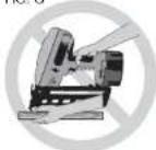
FIG. H

FIG.1
RG, J
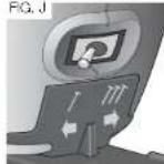
FIG. K
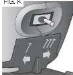
FIG. L

too hard for the fastener to penetrate. Do not use the body of the tool or top cap as a hammer. Discharged fasteners may follow unexpected path and cause injury. (Figs. D, F)
- Always keep fingers clear of nail track of magazine to prevent injury from inadvertent release of the pusher. (Fig. G)
• Refer to the Maintenance and Repairs sections for detailed information on the proper maintenance of the tool. - Always operate the tool in a clean, lighted area. Be sure the work surface is clear of any debris and be careful not to lose footing when working in elevated environments such as rooftops.
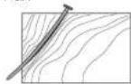
- Do not drive fasteners near edge of material. The workpiece may split causing the fastener to ricochot, injuring you or a co-worker. Be aware that the nail may follow the grain of the wood (shiner), causing it to protrude unexpectedly from the side of the work material. Drive the chisel point of the nail perpendicular to the grain to reduce risk of injury. (Figs. E, F, L)
- Keep hands and body parts clear of immediate work area. Hold workpiece with clamps when necessary to keep hands and body out of potential harm. Be sure the workpiece is properly secured before pressing the nailer against the material. The contact trip may cause the work material to shift unexpectedly. (Fig. G)
- Do not use tool in the presence of flammable dust, gases or fumes. The tool may produce a spark that could ignite gases causing a fire. Driving a nail into another nail may also cause a spark. (Fig. H)
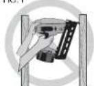
- Keep face and body parts away from back of the tool cap when working in restricted areas. Sudden recoil can result in impact to the body, especially when nailing into hard or dense material. (Fig. 1)
- Grip tool firmly to maintain control while allowing tool to recoil away from work surface as fastener is driven. In Bump mode, if contact trip is allowed to recontact work surface before trigger is released, an unwanted fastener will be fired.
- Choice of triggering method is important. Check the manual for triggering options.
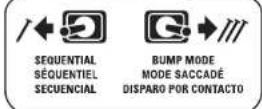
BUMP/SEQUENTIAL SELECTOR SWITCH
Sequential Action ↗ (Fig. J)
- When using the tool in sequential action, do not actuate tool unless the tool is placed firmly against the workpiece.
Bump Action III (Fig. K)
- When using the tool in bump action, be careful of unintentional double fires resulting from tool recoil. Unwanted fasteners may be driven if the contact trip is allowed to accidentally re-contact the work surface.
TO AVOID DOUBLE FIRES:
• Do not engage the tool against the work surface with a strong force.
- Allow the tool to recoil fully after each actuation.
- Use sequential action trigger.
- When "bump" actuating the finish nailer, always keep tool in
control. Inaccurate placement of tool can result in misdirected discharge of a fastener.
- Do not drive nails onto the heads of other fasteners. Strong recoil, jammed fasteners, or ricocheted nails may result. (Fig. L)
- Be aware of material thickness when using nailer. A protruding nail may cause injury.
- DEPTH ADJUSTMENT: To reduce risk of serious injury from accidental actuation when attempting to adjust depth, ALWAYS;
- Remove battery pack.
- Engage contact trip lock-off (Fig. M).
- Avoid contact with trigger during adjustments
- Do not drive nails blindly into walls, floors or other work areas. Fasteners driven into live electrical wires, plumbing, or other types of obstructions can result in injury. (Fig. N)
- Stay alert, watch what you are doing and use common sense when operating a power tool. Do not use tool while tired or under the influence of drugs, alcohol, or medication. A moment of inattention while operating power tools may result in serious personal injury.
- Air vents often cover moving parts and should be avoided. Loose clothes, jewelry or long hair can be caught in moving parts.
▲ WARNING: ALWAYS use safety glasses. Everyday eyeglasses are NOT safety glasses. Also use face or dust mask if cutting operation is dusty. ALWAYS WEAR CERTIFIED SAFETY EQUIPMENT:
• ANSI Z87.1 eye protection (CAN/CSA Z94.3),
• ANSI S12.6 (S3.19) hearing protection,
• NIOSH/OSHA/MSHA respiratory protection.
▲ WARNING: Some dust created by power sanding, sawing, grinding, drilling, and other construction activities contains chemicals known to the State of California to cause cancer, birth defects or other reproductive harm. Some examples of these chemicals are:
- lead from lead-based paints,
- crystalline silica from bricks and cement and other masonry products, and - arsenic and chromium from chemically-treated lumber.
Your risk from these exposures varies, depending on how often you do this type of work. To reduce your exposure to these chemicals: work in a well ventilated area, and work with approved safety equipment, such as those dust masks that are specially designed to filter out microscopic particles.
- Avoid prolonged contact with dust from power sanding, sawing, grinding, drilling, and other construction activities. Wear protective clothing and wash exposed areas with soap and water. Allowing dust to get into your mouth, eyes, or lay on the skin may promote absorption of harmful chemicals.
FIG. M
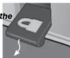
FIG. N
▲WARNING: Use of this tool can generate and/or disperse dust, which may cause serious and permanent respiratory or other injury. Always use NIOSH/OSHA approved respiratory protection appropriate for the dust exposure. Direct particles away from face and body.
WARNING: Always wear proper personal hearing protection that conforms to ANSI S12.6 (S3.19) during use. Under some conditions and duration of use, noise from this product may contribute to hearing loss.
CAUTION: When not in use, place tool on its side on a stable surface where it will not cause a tripping or falling hazard. Some tools with large battery packs will stand upright on the battery pack but may be easily knocked over.
- The label on your tool may include the following symbols. The symbols and their definitions are as follows:
V....volts
Hz.....hertz
min ......minutes
--- or DC.....direct current
Class / Construction
(grounded)
Class II Construction
(double insulated)
.../min ......per minute
IPM....impacts per minute
SPM ......strokes per minute
A.....amperes
W.....watts
\~ or AC......alternating current
≈ or AC/DC.....alternating or direct current
n_0 no load speed
n......rated speed
⊕ earthing terminal
A....safety alert symbol
BPM.....beats per minute
RPM......revolutions per minute
sfpm......surface feet per minute
Important Safety Instructions for All Battery Packs
When ordering replacement battery packs, be sure to include catalog number and voltage. Consult the chart at the end of this manual for compatibility of chargers and battery packs. The battery pack is not fully charged out of the carton. Before using the battery pack and charger, read the safety instructions below. Then follow charging procedures outlined.
READ ALL INSTRUCTIONS
- Do not charge or use battery in explosive atmospheres, such as in the presence of flammable liquids, gases or dust. Inserting or removing the battery from the charger may ignite the dust or fumes.
- NEVER force battery pack into charger. DO NOT modify battery pack in any way to fit into a non-compatible charger as battery pack may rupture causing serious personal injury. Consult the chart at the end of this manual for compatibility of batteries and chargers.
- Charge the battery packs only in D eWALT chargers.
• DO NOT splash or immerse in water or other liquids. - Do not store or use the tool and battery pack in locations where the temperature may reach or exceed 105^ (40 °C) (such as outside sheds or metal buildings in summer).
▲DANGER: Electrocution hazard. Never attempt to open the battery pack for any reason. If battery pack case is cracked or damaged, do not insert into charger. Do not crush, drop or damage battery pack. Do not use a battery pack or charger that has received a sharp blow, been dropped, run over or damaged in any way (i.e., pierced with a nail, hit with a hammer, stepped on). Electric shock or electrocution may result. Damaged battery packs should be returned to service center for recycling.
NOTE: Battery storage and carrying caps are provided for use whenever the battery is out of the tool or charger. Remove cap before placing battery in charger or tool.
⚠ WARNING: Fire hazard. Do not store or carry battery so that metal objects can contact exposed battery terminals. For example, do not
place battery in aprons, pockets, tool boxes, product kit boxes, drawers, etc., with loose nails, screws, keys, etc. without battery cap. Transporting batteries can possibly cause fires if the battery terminals inadvertently come in contact with conductive materials such as keys, coins, hand tools and the like. The U.S. Department of Transportation Hazardous Material Regulations (HMR) actually prohibit transporting batteries in commerce or on airplanes (i.e., packed in suitcases and carry-on luggage) UNLESS they are property protected from short circuits. So when transporting individual batteries, make sure that the battery terminals are protected and well insulated from materials that could contact them and cause a short circuit.
SPECIFIC SAFETY INSTRUCTIONS FOR NICKEL CADMIUM (NiCd) OR NICKEL METAL HYDRIDE (NiMH)
- Do not incinerate the battery pack even if it is severely damaged or is completely worn out. The battery pack can explode in a fire.
- A small leakage of liquid from the battery pack cells may occur under extreme usage or temperature conditions. This does not indicate a failure.
However, if the outer seal is broken:
a. and the battery liquid gets on your skin, immediately wash with soap and water for several minutes.
b. and the battery liquid gets into your eyes, flush them with clean water for a minimum of 10 minutes and seek immediate medical attention. (Medical note: The liquid is 25–35% solution of potassium hydroxide.)
SPECIFIC SAFETY INSTRUCTIONS FOR LITHIUM ION (Li-Ion)
- Do not incinerate the battery pack even if it is severely damaged or is completely worn out. The battery pack can explode in a fire. Toxic fumes and materials are created when lithium ion battery packs are burned.
- If battery contents come into contact with the skin, immediately wash area with mild soap and water. If battery liquid gets into the eye, rinse water over the open eye for 15 minutes or until irritation ceases. If medical attention is needed, the battery electrolyte is composed of a mixture of liquid organic carbonates and lithium salts.
- Contents of opened battery cells may cause respiratory irritation. Provide fresh air. If symptoms persist, seek medical attention.
▲ WARNING:Burn hazard. Battery liquid may be flammable if exposed to spark or flame.
The RBRC™ Seal
The RBRC™ (Rechargeable Battery Recycling Corporation) Seal on the nickel cadmium, nickel metal hydride or lithium ion batteries (or battery packs) indicate that the costs to recycle these batteries (or battery packs) at the end of their useful life have already been paid by DFWALT. In some areas, it is illegal to place spent nickel cadmium, nickel metal hydride or lithium ion batteries in the trash or municipal solid waste stream and the RBRC program provides an environmentally conscious alternative.
RBRC™ in cooperation with DeWALT and other battery users, has established programs in the United States and Canada to facilitate the collection of spent nickel cadmium, nickel metal hydride or lithium ion batteries. Help protect our environment and conserve natural resources by returning the spent nickel cadmium, nickel metal hydride or lithium ion batteries to an authorized DeWALT service center or to your local retailer for recycling. You may also contact your local recycling center for information on where to drop off the spent battery.
RBRC™ is a registered trademark of the Rechargeable Battery Recycling Corporation.


Important Safety Instructions for All Battery Chargers
SAVE THESE INSTRUCTIONS: This manual contains important safety and operating instructions for battery chargers.
- Before using charger, read all instructions and cautionary markings on charger, battery pack, and product using battery pack.
▲ DANGER: Electrocution hazard. 120 volts are present at charging terminals. Do not probe with conductive objects. Electric shock or electrocution may result.
⚠ WARNING: Shock hazard. Do not allow any liquid to get inside charger. Electric shock may result
CAUTION: Bum hazard. To reduce the risk of injury, charge only DcWALT rechargeable batteries. Other types of batteries may burst causing personal injury and damage.
NOTICE: Under certain conditions, with the charger plugged in to the power supply, the exposed charging contacts inside the charger can be shorted by foreign material. Foreign materials of a conductive nature such as, but not limited to, grinding dust, metal chips, steel wool, aluminum foil, or any buildup of metallic particles should be kept away from charger cavities. Always unplug the charger from the power supply when there is no battery pack in the cavity. Unplug charger before attempting to clean.
- DO NOT attempt to charge the battery pack with any chargers other than the ones in this manual. The charger and battery pack are specifically designed to work together.
- These chargers are not intended for any uses other than charging D EWALT rechargeable batteries. Any other uses may result in risk of fire, electric shock or electrocution.
- Do not expose charger to rain or snow.
- Pull by plug rather than cord when disconnecting charger. This will reduce risk of damage to electric plug and cord.
- Make sure that cord is located so that it will not be stepped on, tripped over, or otherwise subjected to damage or stress.
- Do not use an extension cord unless it is absolutely necessary. Use of improper extension cord could result in risk of fire, electric shock, or electrocution.
- When operating a power tool outdoors, use an extension cord suitable for outdoor use. Use of a cord suitable for outdoor use reduces the risk of electric shock.
- An extension cord must have adequate wire size (AWG or American Wire Gauge) for safety. The smaller the gauge number of the wire, the greater the capacity of the cable, that is 16 gauge has more capacity than 18 gauge. An undersized cord will cause a drop in line voltage resulting in loss of power and overheating. When using more than one extension to make up the total length, be sure each individual extension contains at least the minimum wire size. The following table shows the correct size to use depending on cord length and nameplate ampere rating. If in doubt, use the next heavier gauge. The smaller the gauge number, the heavier the cord.
| Minimum Gauge for Cord Sets | ||||||
| Ampere Rating | Volts Total Length of Cord in Feet (meters) | |||||
| 120V 25 (7.6) 50 (15.2) 100 (30.5) 150 (45.7) | ||||||
| 240V 50 (15.2) 100 (30.5) 200 (61.0) 300 (91.4) | ||||||
| More Than | Not More Than | AWG | ||||
| 0 | 6 | 18 | 16 | 16 | 14 | |
| 6 | 10 | 18 | 16 | 14 | 12 | |
| 10 | 12 | 16 | 16 | 14 | 12 | |
| 12 | 16 | 14 | 12 | Not Recommended | ||
- Do not place any object on top of charger or place the charger on a soft surface that might block the ventilation slots and result in excessive internal heat. Place the charger in a position away from any heat source. The charger is ventilated through slots in the top and the bottom of the housing.
- Do not operate charger with damaged cord or plug.
- Do not operate charger if it has received a sharp blow, been dropped, or otherwise damaged in any way. Take it to an authorized service center.
- Do not disassemble charger; take it to an authorized service center when service or repair is required. Incorrect reassembly may result in a risk of electric shock, electrocution or fire.
- Disconnect the charger from the outlet before attempting any cleaning. This will reduce the risk of electric shock. Removing the battery pack will not reduce this risk.
• NEVER attempt to connect two chargers together. - The charger is designed to operate on standard 120 volt household electrical power. Do not attempt to use it on any other voltage. This does not apply to the vehicular charger.
Using Automatic Tune-Up™ Mode
The automatic Tune-Up™ Mode equalizes or balances the individual cells in the battery pack allowing it to function at peak capacity. Battery packs should be tuned up weekly or after 10 charge/discharge cycles or whenever the pack no longer delivers the same amount of work. To use the automatic Tune-Up™, place the battery pack in the charger and leave it for at least 8 hours. The charger will cycle through the following modes.
- The red light will blink continuously indicating that the 1-hour charge cycle has started.
- When the 1-hour charge cycle is complete, the light will stay on continuously and will no longer blink. This indicates that the pack is fully charged and can be used at this time.
- If the pack is left in the charger after the initial 1-hour charge, the charger will begin the Automatic Tune-Up™ mode. This mode continues up to 8 hours or until the individual cells in the battery pack are equalized. The battery pack is ready for use and can be removed at any time during the Automatic Tune-Up™ mode.
- Once the Automatic Tune-Up™ mode is complete, the charger will begin a maintenance charge; the red indicator will remain lit.
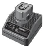
Chargers
Your tool uses a DEWALT charger. Be sure to read all safety instructions before using your charger. Consult the chart at the end of this manual for compatibility of chargers and battery packs.
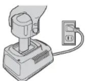
Charging Procedure (Fig. 2)
▲DANGER: Electrocution hazard. 120 volts are present at charging terminals. Do not probe with conductive objects. Electric shock or electrocution may result.
- Plug the charger into an appropriate outlet before inserting battery pack.
- Insert the battery pack into the charger, as shown in Figure 2, making sure the pack is fully seated in charger. The red (charging) light will blink continuously indicating that the charging process has started.
- The completion of charge will be indicated by the red light remaining on continuously. The pack is fully charged and may be used at this time or left in the charger.
FIG. 2
15-MINUTE CHARGER
1-HOUR CHARGER
Indicator Light Operation

text_image
PACK CHARGING..... FULLY CHARGED..... HOT/COLD PACK DELAY..... REPLACE PACK..... PROBLEM POWER LINE.....Charge Indicators
Some chargers are designed to detect certain problems that can arise with battery packs. Problems are indicated by the red light flashing at a fast rate. If this occurs, re-insert battery pack into the charger. If the problem persists, try a different battery pack to determine if the charger is OK. If the new pack charges correctly, then the original pack is defective and should be returned to a service center or other collection site for recycling. If the new battery pack dicits the same trouble indication as the original, have the charger tested at an authorized service center.
HOT/COLD PACK DELAY
Some chargers have a Hot/Cold Pack Delay feature: when the charger detects a battery that is hot, it automatically starts a Hot Pack Delay, suspending charging until the battery has cooled. After the battery has cooled, the charger automatically switches to the Pack Charging mode. This feature ensures maximum battery life. The red light flashes long, then short while in the Hot Pack Delay mode.
PROBLEM POWER LINE
Some chargers have a Problem Power Line indicator. When the charger is used with some portable power sources such as generators or sources that convert DC to AC, the charger may temporarily suspend operation, flashing the red light with two fast blinks followed by a pause. This indicates the power source is out of limits.
LEAVING THE BATTERY PACK IN THE CHARGER
The charger and battery pack can be left connected with the red light glowing indefinitely. The charger will keep the battery pack fresh and fully charged.
NOTE: A battery pack will slowly lose its charge when kept out of the charger. If the battery pack has not been kept on maintenance charge, it may need to be recharged before use. A battery pack may also slowly lose its charge if left in a charger that is not plugged into an appropriate AC source.
WEAK BATTERY PACKS: Chargers can also detect a weak battery pack. Such batteries are still usable but should not be expected to perform as much work. The charger will indicate to replace battery pack.
Important Charging Notes
- Longest life and best performance can be obtained if the battery pack is charged when the air temperature is between 65 °F and 75 °F (18°–24°C). DO NOT charge the battery pack in an air temperature below +40 °F (+4.5°C), or above +105 °F (+40.5°C). This is important and will prevent serious damage to the battery pack.
- The charger and battery pack may become warm to touch while charging. This is a normal condition, and does not indicate a problem. To facilitate the cooling of the battery pack after use, avoid placing the charger or battery pack in a warm environment such as in a metal shed, or an uninsulated trailer.
- If the battery pack does not charge properly:
a. Check operation of receptacle by plugging in a lamp or other appliance;
b. Check to see if receptacle is connected to a light switch which turns power off with you turn out the lights;
c. Move charger and battery pack to a location where the surrounding air temperature approximately 65 °F–75 °F (18 °–24 °C);
d. If charging problems persist, take the tool, battery pack and charger to your lo service center.
- The battery pack should be recharged when it fails to produce sufficient power on jobs which were easily done previously. DO NOT CONTINUE to use under these conditions. Follow the charging procedure. You may also charge a partially used pack whenever you desire with no adverse effect on the battery pack.
- Under certain conditions, with the charger plugged into the power supply, the exposed charging contacts inside the charger can be shorted by foreign material. Foreign materials of a conductive nature such as, but not limited to, grinding dust, metal chips, steel wool, aluminum foil, or any buildup of metallic particles should be kept away from charger cavities. Always unplug the charger from the power supply when there is no battery pack in the cavity. Unplug charger before attempting to clean.
- Do not freeze or immerse charger in water or any other liquid.
A WARNING: Shock hazard. Don't allow any liquid to get inside charger. Electric shock may result.
▲WARNING: Burn hazard. Never attempt to open the battery pack for any reason. If the plastic housing of the battery pack breaks or cracks, return to a service center for recycling.
Storage Recommendations
- The best storage place is one that is cool and dry away from direct sunlight and excess heat or cold.
- For long storage, it is recommended to store a fully charged battery pack in a cool dry place out of the charger for optimal results.
NOTE: Battery packs should not be stored completely depleted of charge. The battery pack will need to be recharged before use.
SAVE THESE INSTRUCTIONS FOR FUTURE USE
COMPONENTS
⚠ WARNING: Lock the contact trip in the off position, disconnect battery pack from tool and remove nail strips from magazine before making adjustments or personal injury may result. Refer to Figure 1 at the beginning of this manual for a complete list of components.
OPERATION
⚠WARNING: Read the section titled Nailer Safety Warnings at the beginning of this manual. Always wear eye and ear protection when operating this tool. Koop the nailer pointed away from yourself and others. For safe operation, complete the following procedures and checks before each use of the nailer.
- Wear proper eye, hearing and respiratory protection.
- Remove battery pack from tool.
- Lock the pusher in the back position and remove all nail strips from the magazine.
- Check for smooth and proper operation of contact trip and pusher assemblies. Do not use tool if either assembly is not functioning properly. NEVER use a tool that has the contact trip restrained in the up position.
- NEVER use a tool that has damaged parts.
WARNING: To reduce the risk of personal injury, disconnect battery pack from tool before performing maintenance, clearing a jammed nails, leaving work area, moving tool to another location or handing the tool to another person.
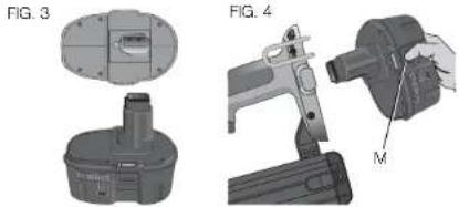
Installing and Removing the Battery Pack (Fig. 3, 4)
NOTE: For best results, make sure your battery pack is fully charged.
To install the battery pack into the tool handle, align the battery pack with the rails inside the tool's handle and slide it into the handle until the battery pack is firmly seated in the tool and ensure that it does not disengage.
To remove the battery pack from the tool, press the release button (M) and firmly pull the battery pack out of the tool handle. Insert it into the charger as described in the charger section of this manual.
NOTICE: Do not store tool with battery pack installed. To prevent damage to the pack and to ensure best battery life, store battery packs out of the tool or charger in a cool, dry location.
natural_image
Technical drawings of mechanical components, including a cylindrical device and a handheld device with labeled part M (no text or symbols beyond labels)Mode Selection (Fig. 5)
WARNING: Always wear proper eye [ANSI Z87.1 (CAN/CSA Z94.3)] and ANSI S12.6 (S3.19) hearing protection when operating tool.
The DEWALT cordless nailers are assembled in accordance with the ANSI Standard SNT-101-2002.
Before operating this tool, look at the selector switch to determine the actuation mode. Read all instructions before selecting actuation mode.
FIG. 5
WARNING: Keep fingers AWAY from trigger when not driving fasteners to avoid accidental firing. NEVER carry tool with finger on trigger. In bump mode tool will fire a fastener if safety is bumped while trigger is depressed.
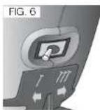
SEQUENTIAL ACTION /
Use sequential action for intermittent nailing where very careful and accurate placement is desired.
To operate the nailer in sequential action mode:
- Flip the switch located on the body of the tool just between the trigger and magazine to the left, as shown in Figure 6.
- Fully depress nosepiece against the work surface (motor will start).
- Pull trigger (nail will drive into work surface).
- Release trigger.
- Lift nosepiece off work surface.
- Repeat steps 2 through 4 for next application.
CAUTION: The contact trip needs to be depressed followed by a trigger pull for each nail followed by a release of both the contact trip and trigger after each nail.
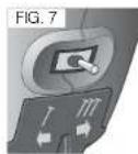
BUMP ACTION
Bump action is intended for rapid nailing on flat, stationary surfaces.
When using bump action, two methods are available: place actuation and bump actuation.
Flip the switch located on the body of the tool just between the trigger and magazine to the right as shown in Figure 7.
To operate the tool using the PLACE ACTUATION method:
▲CAUTION: A nail will fire each time the trigger is depressed as long as the contact trip remains depressed.
- Depress the contact trip against the work surface.
- Depress the trigger.
To operate the tool using the BUMP ACTUATION method:
- Depress the trigger.
- Push the contact trip against the work surface. As long as the trigger is depressed, the tool will fire a nail every time the contact trip is depressed. This allows the user to drive multiple nails in sequence.
▲CAUTION: Do not keep trigger depressed when tool is not in use. Keep the contact trip lock-off engaged in the locked position when the tool is not in use.
Preparing the Tool
A CAUTION: NEVER spray or in any other way apply lubricants or cleaning solvents inside the tool. This can seriously affect the life and performance of the tool.
NOTE: The battery pack is not fully charged out of the carton. Follow instructions outlined (see Charging Procedures).
-
Read the Safety Instruction section of this manual.
-
Wear eye and ear protection.
- Ensure magazine is empty of all fasteners.
- Check for smooth and proper operation of contact trip and pusher assemblies. Do not use tool if either assembly is not functioning properly. NEVER use a tool that has the contact trip restrained in the actuated position.
- Keep tool pointed away from yourself and others.
- Insert fully charged battery pack.
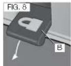
Using the Contact Trip Lock-off (Fig. 8, 9)
WARNING: To reduce the risk of serious personal injury, DO NOT keep trigger depressed when tool is not in use. Keep the contact trip lock-off switch LOCKED (Fig. 8) when the tool is not in use.
WARNING: To reduce the risk of serious personal injury, lock off the contact trip, disconnect battery pack from tool and remove fasteners from magazine before making adjustments. Serious personal injury may result.
▲WARNING: Always wear eye and ear protection when operating tool.
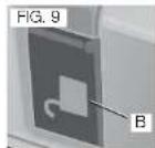
Each DeWALT nailer is equipped with a contact trip lock-off (B) which when pulled downward with the lock symbol showing as shown, prevents the tool from firing a nail.
When the contact trip lock-off is folded in as shown, the tool will be fully operational. The contact trip lock-off should always be locked off whenever any adjustments are made or when tool is not in immediate use.
NOTE: Tools equipped with selective actuation, when in bump fire mode will allow the motor to start upon trigger pull. This is normal operation. The contact trip lock-off constrains the contact trip from discharging a nail.
Loading the Tool
WARNING: Keep the tool pointed away from yourself and others. Serious personal injury may result.
AWARNING: Never load nails with the contact trip or trigger activated. Personal injury may result.
⚠WARNING: Always remove battery pack before loading or unloading nails. Serious personal injury may result.
LOAD AND DRAW METHOD (FIG. 1)
- Insert fasteners into the rear of the magazine (G).
- Pull pusher (H) back until the nail follower falls behind the nails.
- Release the pusher.
LOCK AND LOAD METHOD
▲CAUTION: Keep fingers clear of pusher to prevent injury.
ACAUTION: The contact trip lock-off should always be locked off whenever any adjustments are made or when tool is not in use.
- Pull pusher back until it locks.
- Insert fasteners into the rear of the magazine.
- Push forward on the pusher until it releases and slides forward.
UNLOADING THE TOOL
ACAUTION: The contact trip lock-off should always be locked off whenever any adjustments are made or when tool is not in use.
- Pull pusher back until it locks.
- Tip the tool up until the nails slide freely out the back of the magazine
- Open the jam clear door on the nosepiece to verify there are no nails remaining.
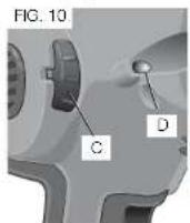
Adjusting Depth (Fig. 10)
The depth that the fastener is driven can be adjusted using the depth adjustment wheel (C) on the side of the tool.
⚠WARNING: To reduce risk of serious injury from accidental actuation when attempting to adjust depth, ALWAYS:
- Remove battery pack.
- Engage contact trip lock-off.
- Avoid contact with trigger during adjustments.
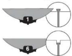
- To drive the nail shallower, rotate the depth adjustment wheel (C) counterclockwise. There are six depth settings, 1 being the shallowest and 6 being the deepest.
- To sink a nail deeper, rotate the depth adjustment wheel (C) clockwise.
text_image
1 6Headlights (Fig. 10)
There is a headlight (D) located on each side of the nailer. Headlights turn on upon battery insertion, activation of the trigger, or depressing the contact trip. The lights will automatically shut off after 10 seconds unless tool remains in use.
NOTE: These headlights are for lighting the immediate work surface and are not intended to be used as flashlights.
LOW BATTERY INDICATOR: The headlights will flash four consecutive times and then shut down to indicate low battery.
LOW BATTERY..... ■■■■
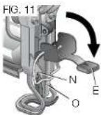
JAMMED NAIL INDICATOR: The headlights will flash continually if a nail becomes jammed in the nosepiece (see Clearing a Jammed Nail).
If a nail becomes jammed in the nosepiece, keep the tool pointed away from you and follow these instructions to clear:
- Remove battery pack from tool and engage contact trip lock-off.
- Pull the pusher back until it locks in place then remove the nails.
- Lift the jam clearing latch (E) then pull up to open front door (O).
- Remove bent nail, using pliers if necessary.
- If driver blade is in the down position, insert screwdriver or other rod into nosepiece and push driver blade back in position.
- Close the front door and engage the wireform under the 2 arms (N) on the nosepiece. Push latch until it locks in place.
- Reinsert battery pack.
NOTE: The tool will disable itself and not reset until the battery pack has been removed and reinserted. - Reinsert nails into magazine (see Loading the Tool).
- Release pusher.
NOTE: Should nails continue to jam frequently in nosepiece, have tool serviced by an authorized DEWALT service center.
Cold Weather Operation
When operating tools at temperatures below freezing:
- Keep tool as warm as possible prior to use.
- Actuate the tool 5 or 6 times into scrap lumber before using.
Hot Weather Operation
Tool should operate normally. However, keep tool out of direct sunlight as excessive heat can deteriorate bumpers and other rubber parts resulting in increased maintenance.
Suspension Hook (Fig. 12)
The DeWALT cordless nailers include an integrated suspension hook (J) and can be attached to either side of the tool to accommodate left- or right-handed users.
If the hook is not desired at all, it can be removed from the tool.
TO REMOVE SUSPENSION HOOK
- Remove battery pack from tool.
- To switch the tool from right- to left-hand usage simply remove the screw from the opposite side of the tool and reassemble on the other side.
- Replace battery pack.
⚠WARNING: Remove nails from magazine before making any adjustments or servicing this tool. Failure to do so may result in serious injury.
ACAUTION: Disconnect battery pack from tool before making any adjustments, changing accessories, servicing, or moving the tool. Such preventative safety measures reduce the risk of starting the tool accidentally.
ACAUTION: When not in use, place tool on its side on a stable surface where it will not cause a tripping or falling hazard. Some tools with large battery packs will stand upright on the battery pack but may be easily knocked over.
MAINTENANCE
WARNING: To reduce the risk of injury, turn unit off and disconnect it from power source before installing and removing accessories, before adjusting or when making repairs. An accidental start-up can cause injury.
Daily Maintenance Chart
ACTION Clean magazine, pusher, and contact trip mechanism.
WHY Permits smooth operation of magazine, reduces wear, and prevents jams.
HOW Blow clean with compressor air. The use of oils, lubricants periodically or solvents is not recommended as they tend to attract debris.
ACTION Before each use, check to insure all screws, nuts and fasteners are tight and undamaged.
WHY Prevents jams and premature failure of tool parts.
HOW Tighten loose screws or other fasteners using the appropriate allen wrench or screwdriver.
Cleaning
▲ WARNING: Blow dirt and dust out of all air vents with clean, dry air at least once a week. To minimize the risk of eye injury, always wear ANSI ZB7.1 approved eye protection when performing this.
▲ WARNING: Never use solvents or other harsh chemicals for cleaning the non-metallic parts of the tool. These chemicals may weaken the plastic materials used in these parts. Use a cloth dampened only with water and mild soap. Never let any liquid get inside the tool; never immerse any part of the tool into a liquid.
CHARGER CLEANING INSTRUCTIONS
▲WARNING: Shock hazard. Disconnect the charger from the AC outlet before cleaning. Dirt and grease may be removed from the exterior of the charger using a cloth or soft non-metallic brush. Do not use water or any cleaning solutions.
Lubrication
▲CAUTION: NEVER spray or in any other way apply lubricants or cleaning solvents inside the tool. This can seriously affect the life and performance of the tool.
DeWALT tools are properly lubricated at the factory and are ready for use. However, it is recommended that, once a year, you take or send the tool to a certified service center for a thorough cleaning and inspection.

Accessories
▲ WARNING: Since accessories, other than those offered by DcWALT, have not been tested with this product, use of such accessories with this tool could be hazardous. To reduce the risk of injury, only DcWALT recommended accessories should be used with this product. Recommended accessories for use with your tool are available at extra cost from your local dealer or authorized service center. If you need assistance in locating any accessory, please contact DcWALT Industrial Tool Co., 701 East Joppa Road, Baltimore, MD 21286, call 1-800-4-DcWALT (1-800-433-9258) or visit our website: www.dewalt.com.
Repairs
⚠WARNING: To reduce the risk of serious personal injury, remove nails from magazine before making any adjustments or servicing this tool.
The charger and battery pack are not serviceable.
To assure product SAFETY and RELIABILITY, repairs, maintenance and adjustment (including brush inspection and replacement) should be performed by a DEWALT factory service center, a DEWALT authorized service center or other qualified service personnel. Always use identical replacement parts. Refer to the Troubleshooting Guide at the end of this section.
CAUTION: Remove nails from magazine before making any adjustments or servicing this tool. Failure to do so may result in serious injury.
TO SERVICE (FIG. 13-17)
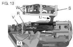
- Remove 3 T25 slotted screws from top cover. Remove cover from housing and set aside.
- Using a nail or punch, apply pressure to the pin (Q) sliding the pin out from the metal structure (Fig. 13).
text_image
FIG. 13 W R V U S Q- Push driver/return assembly (R) toward nosepiece and hold in place against the lower bumper (V) as you roll back the activation arm Assembly (S). Remove activation arm assembly and set aside.
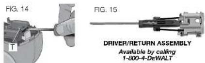
- Use a flat blade screwdriver to pry up on the return cord assembly (T) until the detents release. Lift up to remove (Fig. 14).
- Remove the driver/return assembly (Fig. 15).
text_image
FIG. 14 FIG. 15 T DRIVER/RETURN ASSEMBLY Available by calling 1-800-4-DeWALT- Inspect lower bumper (V), upper bumper (X), and other surfaces for cracks or damage and replace if necessary (Fig. 16). Replace damaged return cord assembly.

text_image
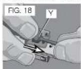
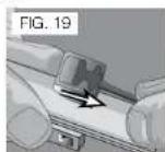
FIG. 16 V X FIG. 17 Y RETURN CORD ASSEMBLY Available by calling 1-800-4-DeWALTTO REPLACE RETURN CORD ASSEMBLY (FIG. 18-19)
NOTE: For correct cord position during assembly, refer to the proper orientation of the return cord assembly in Figure 15.
- Align one of the rubber tabs (Y) from the new return cord assembly with the corresponding slot in the driver (Fig. 18).
- With your finger, push and bend the rubber tab around corner (Fig. 18) while pulling the rubber cord until tab is firmly in place (Fig. 19).
- Repeat above procedure for other rubber cord.
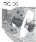
TO REASSEMBLE NAILER (FIG. 13, 20-23)
- Insert the tip of the driver/return assembly blade into the matching hole in the nosepiece (Fig. 20).
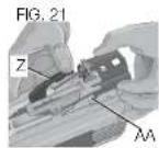
- Move contact trip (Z) to the side while pulling back on the return cord assembly (Fig. 21).
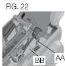
- Engage the hooks (AA) on the return cord assembly to the notch (BB) in the metal structure then push down to snap into detents (Fig. 22).
- Slide the driver/return assembly (R) toward the nosepiece and hold.
- Insert activation arm assembly by first engaging the cam pin (U) to the solenoid; then align the pivot holes (W) to the metal structure (Fig. 13).
-
Slide the pin (Q) through the metal structure, capturing the activation arm assembly and spring.
-
Ensure the activation arm is fully engaged as shown in Figure 23.
- Replace the cover to housing, insert 3 T25 slotted screws and tighten.

natural_image
Cross-sectional mechanical assembly diagram showing internal components and housing (no text or labels)Register Online
Thank you for your purchase. Register your product now for:
- WARRANTY SERVICE: Registering your product will help you obtain more efficient warranty service in case there is a problem with your product.
- CONFIRMATION OF OWNERSHIP: In case of an insurance loss, such as fire, flood or theft, your registration of ownership will serve as your proof of purchase.
- FOR YOUR SAFETY: Registering your product will allow us to contact you in the unlikely event a safety notification is required under the Federal Consumer Safety Act.
Register online at www.dewalt.com/register.
Three Year Limited Warranty
DEWALT will repair, without charge, any defects due to faulty materials or workmanship for three years from the date of purchase. This warranty does not cover part failure due to normal wear or tool abuse. For further detail of warranty coverage and warranty repair information, visit www.dewalt.com or call 1-800-4-DEWALT (1-800-433-9258). This warranty does not apply to accessories or damage caused where repairs have been made or attempted by others. This warranty gives you specific legal rights and you may have other rights which vary in certain states or provinces.
In addition to the warranty, DEWALT tools are covered by our:
1 YEAR FREE SERVICE
DEWALT will maintain the tool and replace worn parts caused by normal use, for free, any time during the first year after purchase.
2 YEARS FREE SERVICE ON DEWALT BATTERY PACKS
DC9071, DC9091, DC9096, DC9280, DC9360, DC9180, DCB120, DCB201 and DCB203
3 YEARS FREE SERVICE ON DEWALT BATTERY PACKS
DCB200, DCB204
DEWALT BATTERY PACKS
Product warranty voided if the battery pack is tampered with in any way. DeWALT is not responsible for any injury caused by tampering and may prosecute warranty fraud to the fullest extent permitted by law.
90 DAY MONEY BACK GUARANTEE
If you are not completely satisfied with the performance of your DeWALT Power Tool, Laser, or Nailer for any reason, you can return it within 90 days from the date of purchase with a receipt for a full refund – no questions asked.
LATIN AMERICA: This warranty does not apply to products sold in Latin America. For products sold in Latin America, see country specific warranty information contained in the packaging, call the local company or see website for warranty information.
FREE WARNING LABEL REPLACEMENT: If your warning labels become illegible or are missing, call 1-800-4-DEWALT (1-800-433-9258) for a free replacement.
text_image
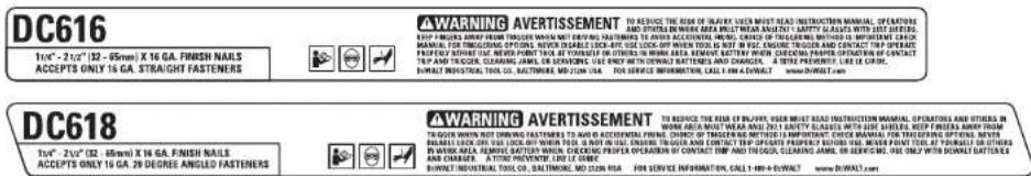
DC616 1/1"- 2/12" (12 - 65mm) X 16 GA. FINISH NAILS ACCEPTS ONLY 16 GA. STRAIGHT FASTENERS WARNING AVERTISSEMENT TO REVECISE THE RISK OF THREAT LEAVES MUST READ INSTRUCTION MANUAL, OPERATIONS AND OTHERS IN WORK AREA MUST WEAR ANY FACTY IS JUSTLY WITH YOUR WRITTEN. EXP: FRESHING AMOUNT FROM TROGERS WHEN NOT BEATING FASTENERS TO ADDIE ACCORDANCE, HEAVY, CHASED, TRAVELING, METHOD IS IMPRIETMENT CHAPICUM ITEMS. IF THE ORDER OFF ON YOUR LET AND WRITE ON YOUR LET, ILLINOY WILL BE USED. THIS PROPERTY HAS BEEN SOLD FOR ANY OTHER IN WORK AREA. REMAIN TERRY WHEN CHECKING PROPERTY ORINFORMATION OF CONTACT THE PLET AND TRUGER, CLEANING AMILE, OR SEVERGING, USE ONLY WITH UNWAL TATTENDS AND CHARGES. A SITE REFERENCE, LIME AT COURT. BOWAT INDUSTRIAL TOOLS CO., BALTIMORE, MD ZION USA. YOU SEE SERVICE INFORMATION, CALL 340-440-VOUT www.bowat.com/ DC618 1/1"- 2/12" (32 - 85mm) X 16 GA. FINISH NAILS ACCEPTS ONLY 16 GA. 29 DEGREE ANGLED FASTENERS WARNING AVERTISSEMENT TO REVECISE THE RISK OF BURPHY, YOUR MUST READ INSTRUCTION MANUAL, OPERATIONS AND OTHERS IN WORK AREA MUST WEAR ANY FACTY IS JUSTLY WITH YOUR WRITTEN. EXP: FISHING AMOUNT FROM TROGERS WHEN NOT BEATING FASTENERS TO ADDIE ACCORDANCE, HEAVY, CHASED, TRAVELING, METHOD IS IMPRIETMENT CHAPICUM ITEMS. IF THE ORDER OFF ON YOUR LET AND WRITE ON YOUR LET, ILLINOY WILL BE USED. THIS PROPERTY HAS BEEN SOLD FOR ANY OTHER IN WORK AREA. REMAIN TERRY WHEN CHECKING PROPERTY ORINFORMATION OF CONTACT THE PLET AND TRUGEP, CLEANING AMILE, OR SEVERGING, USE ONLY WITH BORATE DATTERIES AND CHARGES. A SITE REFERENCE, LIME AT COURT. BOWAT INDUSTRIAL TOOLS CO., BALTIMORE, MD ZION USA. YOU SEE SERVICE INFORMATION, CALL 340-440-VOUT www.bowat.comTROUBLESHOOTING GUIDE
MANY COMMON PROBLEMS CAN BE SOLVED EASILY BY UTILIZING THE CHART BELOW. FOR MORE SERIOUS OR PERSISTENT PROBLEMS, CONTACT A DEWALT SERVICE CENTER OR CALL 1-(800)-4-DEWALT.
WARNING: TO REDUCE THE RISK OF SERIOUS PERSONAL INJURY, ALWAYS DISCONNECT BATTERY PACK FROM TOOL BEFORE ALL REPAIRS
| SYMPTOM CAUSE FIX | ||
| Tool doesn't turn on(Headlights don't turn on) | Tool internal electronics not reset Remove battery, wait 3 seconds and reinsert | |
| Low battery charge or damaged battery Charge or replace battery | ||
| Tominals are dirty or damaged Soo authorized service center | ||
| Contact trip lock is in a locked position Unlock contact trip lock | ||
| Bent contact trip See authorized service center | ||
| Damaged internal electronics See authorized service center | ||
| Tool doesn't actuate (Headlights on, motor does not run) | Motor stops running after 2 seconds Normal operation; release trigger or contact trip and redepress | |
| Contact trip or trigger not depressed See instruction manual | ||
| Damaged trigger Soo authorized service center | ||
| Bent contact trip See authorized service center | ||
| Contact trip lock in the locked position (Sequential mode only) Unlock contact trip lock | ||
| Damaged internal electronics See authorized service center | ||
| Tool doesn't actuate (Headlights flash 4 times) Low battery charge or damaged battery Charge or replace battery | ||
| Tool doesn't actuate (Headlights flash continuously) | Jammed fastener | Remove the battery, clear the jammed fastener, (push driver blade back up manually if necessary) and reinsert battery pack |
| Jammed mechanism | See authorized service center | |
| Tool doesn't actuate (Headlights on, motor runs) | Damaged internal electronics | See authorized service center |
| Tool doesn't actuate (Headlights on, motor runs, driver blade stuck down) | Damaged return system | Replace return system; see authorized service center |
| Debris in nosepiece | Clean nosepiece | |
| Damaged driver/return assembly | Replace driver/return assembly; see authorized service center | |
| Tool operates, but does not drive the fastener fully | Low battery charge or damaged battery | Charge or replace battery |
| Depth adjustment set too shallow | Rotate depth adjustment wheel to a doopor setting | |
| Tool not firmly applied to workpiece | See instruction manual | |
| Material and fastener length too rigorous an application | Choose appropriate material or fastener length | |
| Damaged or worn driver blade tip | Replace driver/return assembly; see authorized service center | |
| Damaged or worn driver/return assembly | Replace driver/return assembly; see authorized service center | |
| Tool operates, but no fastener driven | No fasteners in magazine | Load fasteners into magazine |
| Wrong size or angle fasteners | Use only recommended fasteners | |
| Debris in nosepiece | Clean nosopiece | |
| Debris in magazine | Clean magazine | |
| Worn magazine | Replace magazine; see authorized service center | |
| Damaged or worn driver blade | Replace driver/return assembly; see authorized service center | |
| Damaged pusher spring | Replace spring; see authorized service center | |
| Jammed fastener | Wrong size or angle fasteners | Use only recommended fasteners |
| Damaged or worn driver blade | Replace driver/return assembly; see authorized service center | |
| Material and fastener length too rigorous an application | Material or fastener length inappropriate | |
| Low battery charge or damaged battery Charge or replace battery | ||
| Debris in nosepiece | Clean nosepiece | |
| Debris in magazine | Clean magazine | |
| Worn magazine | Replace magazine; see authorized service center | |
| Worn or damaged pusher spring Replace spring; see authorized service center | ||
text_image
FIG. 1 Angle de 20° DEWALT A L J G H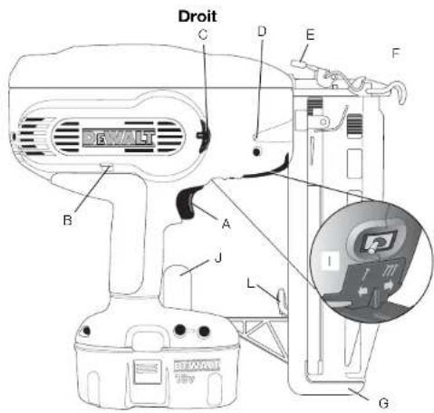
text_image
Droit C D E F B A J L G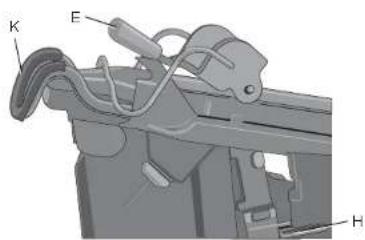
text_image
K E C HLE SECTEUR....●● ●● ●● ●● ●● ●● ●●
Voyants de charge
text_image
Technical diagram of a mechanical device with labeled components (W, R, V, U, S, Q)natural_image
Cross-sectional mechanical assembly diagram showing internal components and housing (no text or labels)Registre en ligne
text_image
DC616 1/4"- 2/12" (32 - 65mm) X 16 GA. FINISH NAIRS ACCEPTS ONLY 16 GA. STRAIGHT FASTENERS WARNING AVERTISSEMENT TO REDECE THE RISK OF INFLATE, USER MEET READ INSTRUCTION MANUAL, OPERATIONS KEEP TURUSER ARMY FROM TRUGER WHEN NOT DUCTOR FASTENERS TO ADDS ACCOUNTED ITEMS. CHECK OR CONTROLS METHOD IN IMPRINTING CHECK FOR EACH ORDER IS NOT USED. IF YOU ARE TO BE PLABLE FOR YOUR OUTPUT AND/OR ACCESS OR ANY OTHERS IN WORK AREA. REMOVErrY POTTER ON YOUR POINT AND/OR ACCESS OR ANY OTHERS IN WORK AREA. REMOVErrY POTTER ON YOUR POINT AND/OR ACCESS OR ANY OTHERS IN WORK AREA. REMOVErrY POTTER ON YOUR POINT AND/OR ACCESS OR ANY OTHERS IN WORK AREA. REMOVErrY POTTER ON YOUR POINT AND/OR ACCESS OR ANY OTHERS IN WORK AREA. REMOVErrY POTTER ON YOUR POINT AND/OR ACCESS OR ANY OTHERS IN WORK AREA. REMOVErrY POTTER ON YOUR POINT AND/OR ACCESS ORANY OTHERS IN WORK AREA. REMOVErrY POTTER ON YOUR POINT AND/OR ACCESS OR ANY OTHERS IN WORK AREA. REMOVErrY POTTER ON YOUR POINT AND/OR ACCESS OR ANY OTHERS IN WORK AREA. REMOVErrY POTTER ON YOUR POINT AND/OR ACCESS OR ANY OTHERS IN WORK AREA. REMOVErrY POTTER ON YOUR POINT AND/OR ACCESS OR ANY OTHERS IN WORK AREA. REMOVErrY POTTER ON YOUR POINT AND/OR ACCESS OR ANY OTHERS IN WORK AVE. PROPOSED ONLY: 2/12" (32 - 65mm) X 16 GA. FINISH NAIRS ACCEPTS ONLY 16 GA. 28 DEGREE ANGLED FASTENERS WARNING AVERTISSEMENT TO REDECE THE RISK OF BULTRY, DUES MEET READ INSTRUCTION MANUAL, OPERATIONS AND OTHERS IN WORK AREA MEET WEAR AND OUT SAFETY SLACES WITH SIDE SHEES. KEEP FINEERS AMRY FROM THE ORDER IS NOT DUCTOR TRUGER AS METHOD IS AVAILABLE. CHECK OR ACCEPT INFORMATION CALL: 0-0-0-0-0-0000000000000000000000000000000000000000000000000000000000000000000000000000000000000000000000 BEZZLE LOCK OFF AT LOOK OFF WHEN THIS IS NOT IN USE ENGLISH TRUGER AND CONTACT TRIP OPERATING PROCEDURE ONLY. REMOVEPTOUNT TO AT PROVIDE TO ALL PROCESSED TRIP AND TRUGER CLEANING AMIRL, OR CHIPSICEL, THE ONLY WITH DURANT BATTERIES AND CHARGES A TIME PREVENTION LIME ON ONE BURELL INDUSTRIAL TOOL CO., BALTIMEL, MO LOIN RUA FOR SERVICE INFORMATION, CALL: 1-49-4-1-1-1-1 DC618 1/4"- 2/12" (32 - 65mm) X 16 GA. FINISH NAIRS ACCEPTS ONLY 16 GA. 28 DEGREE ANGLED FASTENERSGUIDE DE DÉPANNAGE
IL EST POSSIBLE DE RÉSOUDRE FACILEMENT LES PROBLÈMES LES PLUS COMMUNS À L'AIDE DU TABLEAU CI-DESSOUS. POUR DES PROBLÈMES PLUS GRAVES OU DES PROBLÈMES
QUI PERSISTENT, COMMUNIQUER AVEC UN CENTRE DE RÉPARATION D'WALT OU COMPOSER LE 1-800-4-DEWALT.
AVERTISSEMENT : POUR RÉDUIRE LE RISQUE DE BLESSURES CORPORELLES GRAVES, TOUJOURS RETIRER
LE BLOC-PILES DE L'OUTIL AVANT TOUTES RÉPARATIONS.
text_image
Recto C D E F B A J L I G 10V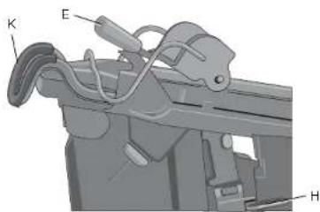
text_image
Technical diagram of a mechanical assembly with labeled parts K, E, and HRefer to Figure 1 at the beginning of this manual for a complete list of components.
natural_image
Technical drawings of mechanical components, including a cylindrical part and a motor assembly (no text or symbols)text_image
FIG. 13 W R V U S Qnatural_image
Cross-sectional mechanical assembly diagram showing internal components (no text or labels)Local D, Col. Obrera (55) 5588 9377
MERIDA, YUC
Calle 63 #459-A - Col. Centro (999) 928 5038
MONTERREY, N.L.
Av. Francisco I. Madero 831 Poniente - Col. Centro (818) 375 23 13
PUEBLA, PUE
17 Norte #205 - Col. Centro (222) 246 3714
QUERETARO, QRO
Av. San Roque 274 - Col. San Gregorio (442) 2 17 63 14
SAN LUIS POTOSI, SLP
text_image
DC616 1/4" - 2/12" (32 - 85mm) X 16 GA. FINISH NAILS ACCEPTS ONLY 16 GA. STRAIGHT FASTENERS WARNING AVERTISSEMENT TO REPROVE THE RISK OF INJURY, USER MUST READ INSTRUCTION MANUAL, OPERATIONS AND OTHERS IN WORK AREA MUST MEAT AND NOT BEATLY GLASSED WITH SIDE SLINES. REEF FINGING AWAY FROM TREGOR WHEN NOT DURING FASTENERS WITH ANN ACCORDINUM FINGING CHECK OR TRIBGING METHOD IS IMPERFORM CHECK MANUAL FOR PROCESSED WORK AREA, OWNER IS SLATED FOR TREGOR. IF RECOCOOP WHEN TOOL IS NOT FOR ANY DISCREPANCY. IF RECOCOOP WHEN TOOL IS NOT FOR ANY DISCREPANCY. IF RECOCOOP WHEN TOOL IS NOT FOR ANY DISCREPANCY. IF RECOCOOP WHEN TOOL IS NOT FOR ANY DISCREPANCY. IF RECOCOOP WHEN TOOL IS NOT FOR ANY DISCREPANCY. IF RECOCOOP WHEN TOOL IS NOT FOR ANY DISCREPANCY. IF RECOCOOP WHEN TOOL IS NOT FOR ANY DISCRE PRACTICE BEFORE USE, NEVER POINT TOOL AT YOURSELF OR OTHERS IN WORK AREA. REMOVE A BATTERY WHEN CHECKING PREPAPER OPERATION OF CONTACT TRAP AND TREGIC, CLEARING ANIMAL, OR SERVATIC INC. ARE ONLY WITH DOWNALL BATTERIES AND CHARGERS. A TITLE PREVENT: LINE LE QDRL DOWALT INDUSTRIAL TOOL CO., BALTIMORE, MD JUN SHA. FOR SERVICE INFORMATION, CALL 1-96-0-DAWALT www.DOWALT.com DC618 1/4" - 2/12" (32 - 85mm) X 16 GA. FINISH NAILS ACCEPTS ONLY 16 GA. 25 DEGREE ANGILED FASTENERS WARNING AVERTISSEMENT TO REPROVE THE RISK OF INJURY, USER MUST READ INSTRUCTION MANUAL, OPERATIONS AND OTHERS IN WORK AREA MUST MEAT AND NOT BEATLY GLASSED WITH ANN CHECKING METHOD IS IMPERFORM CHECK MANUAL FOR PROCESSED WORK AREA, OWNER IS SLATED FOR TREGOR. IF RECOCOOP WHEN TOOL IS NOT FOR ANY DISCREPANCY. IF RECOCOOP WHEN TOOL IS NOT FOR ANY DISCREPANCY. IF RECOCOOP WHEN TOOL IS NOT FOR ANY DISCRE PRACTICE BEFORE USE, NEVER POINT TOOL AT YOURSELF OR OTHERS IN WORK AREA. REMOVE A BATTERY WHEN CONTACT TRAP AND TREGIC, CLEARING ANIMAL, OR SERVATIC INC. ARE ONLY WITH DOWNALL BATTERIES AND CHARGERS. A TITLE PREVENT: LINE LE QDRL DOWALT INDUSTRIAL TOOL CO., BALTIMORE, MD JUN SHA. FOR SERVICE INFORMATION, CALL 1-96-0-DAWALT www.DOWALT.comSOLAMENTE PARA PROPÓSITO DE MÉXICO:
IMPORTADO POR: DI-WALT INDUSTRIAL TOOL CO. S.A. DE C.V.
AVENIDA ANTONIO DOVALI JAIME, # 70 TORRE B FISO 9
COLONIA LA FE, SANTA FÉ
CÓDIGO POSTAL: 01210
| DEWALT Battery and Charger Systems | |||||||||||||||||||||||
| Battery Output Chargers/Charge Time (Minutes) - Chargeurs/Durée de charge (Minutes) - Cargadores de baterias/Tiempo de carga (Minutos) | |||||||||||||||||||||||
| 120 Volts 12 Volts | |||||||||||||||||||||||
| Cat # | Voltage | DW9106 | DW9118 | DW9107 | DW9106 | DW9116 | DW9216 | DW9117 | DW911 | DC011 | DC022 | DC9000 | DC9310 | DC9320 | DCB095 | DCB100 | DCB101 | DCB103 | DW0246 | DCB119 | DW0249 | DW9109 | DC9319 |
| DC9380 | 36 | X | X | X | X | X | X | X | X | X | X | 60 | X | X | X | X | X | X | X | X | X | X | X |
| DC9280 | 28 | X | X | X | X | X | X | X | X | X | X | 60 | X | X | X | X | X | X | X | X | X | X | X |
| DW0242 | 24 | X | X | X | X | X | X | X | X | X | X | X | X | X | X | X | X | X | 60 | X | 60 | X | X |
| DC9396 | 18 | X | X | X | 60 | 60 | 60 | 20 | 60 | 60 | 60 | X | 60 | 60 | X | X | X | 60 | X | X | X | 60 | 60 |
| DC9395 | 18 | X | X | X | 45 | 45 | 45 | 15 | 45 | 45 | 45 | X | 45 | 45 | X | X | X | 45 | X | X | X | 45 | 45 |
| DC9180 | 18 | X | X | X | X | X | X | X | X | X | X | X | 60 | 60 | X | X | X | 60 | X | X | X | X | 60 |
| DC9181 | 18 | X | X | X | X | X | X | X | X | X | X | X | 30 | 30 | X | X | X | 30 | X | X | X | X | 30 |
| DC8380 | 8 | X | X | X | X | X | X | X | X | X | X | X | X | X | 60 | X | X | X | X | X | X | X | X |
| DC83200 | 20 | X | X | X | X | X | X | X | X | X | X | X | X | X | X | X | 60 | 60 | X | 90 | X | X | X |
| DC8201 | 20 | X | X | X | X | X | X | X | X | X | X | X | X | X | X | X | 30 | 30 | X | 45 | X | X | X |
| DC8203 | 20 | X | X | X | X | X | X | X | X | X | X | X | X | X | X | X | 40 | 40 | X | 60 | X | X | X |
| DC8204 | 20 | X | X | X | X | X | X | X | X | X | X | X | X | X | X | X | 80 | 80 | X | 120 | X | X | X |
| DW9096 | 18 | X | X | X | 60 | 60 | 60 | 20 | 60 | 60 | 60 | X | 60 | 60 | X | X | X | 60 | X | X | X | 60 | 60 |
| DW9098 | 18 | X | X | X | 30 | 30 | 30 | 12 | 30 | 30 | 30 | X | 30 | 30 | X | X | X | 30 | X | X | X | 30 | 30 |
| DW9099 | 18 | X | X | X | 45 | 45 | 45 | 15 | 45 | 45 | 45 | X | 45 | 45 | X | X | X | 45 | X | X | X | 45 | 45 |
| DC9081 | 14.4 | 90 | 115 | 60 | 60 | 60 | 60 | 20 | 60 | 60 | 60 | X | 60 | 60 | X | X | X | 60 | X | X | X | 60 | 60 |
| DC9094 | 14.4 | 60 | 90 | 45 | 45 | 45 | 45 | 15 | 45 | 45 | 45 | X | 45 | 45 | X | X | X | 45 | X | X | X | 45 | 45 |
| DW9091 | 14.4 | 60 | 90 | 45 | 45 | 45 | 45 | 15 | 45 | 45 | 45 | X | 45 | 45 | X | X | X | 45 | X | X | X | 45 | 45 |
| DW9094 | 14.4 | 45 | 60 | 30 | 30 | 30 | 30 | 12 | 30 | 30 | 30 | X | 30 | 30 | X | X | X | 30 | X | X | X | 30 | 30 |
| DC8120 | 12 | X | X | X | X | X | X | X | X | X | X | X | X | X | X | 40 | 30 | 30 | X | 40 | X | X | X |
| DC9071 | 12 | 90 | 115 | 60 | 60 | 60 | 60 | 20 | 60 | 60 | 60 | X | 60 | 60 | X | X | X | 60 | X | X | X | 80 | 60 |
| DW9093 | 12 | 40 | X | X | X | X | X | X | X | X | X | X | X | X | X | X | X | X | X | X | X | X | X |
| DW9071 | 12 | 60 | 90 | 45 | 45 | 45 | 45 | 15 | 45 | 45 | 45 | X | 45 | 45 | X | X | X | 45 | X | X | X | 45 | 45 |
| DW9072 | 12 | 45 | 60 | 30 | 30 | 30 | 30 | 12 | 30 | 30 | 30 | X | 30 | 30 | X | X | X | 30 | X | X | X | 30 | 30 |
| DW9049 | 8.6 | 40 | X | X | X | X | X | X | X | X | X | X | X | X | X | X | X | X | X | X | X | X | X |
| DW9061 | 8.6 | 60 | 90 | 45 | 45 | 45 | 45 | 15 | 45 | 45 | 45 | X | 45 | 45 | X | X | X | 45 | X | X | X | 45 | 45 |
| DW9062 | 8.6 | 45 | 60 | 30 | 30 | 30 | 30 | 12 | 30 | 30 | 30 | X | 30 | 30 | X | X | X | 30 | X | X | X | 30 | 30 |
| DW9057 | 7.2 | 45 | 60 | 30 | 30 | 30 | 30 | 12 | 30 | 30 | 30 | X | 30 | 30 | X | X | X | 30 | X | X | X | 30 | 30 |
DEWALT Industrial Tool Co., 701 East Joppa Road, Baltimore, MD 21286
(JAN13)
Part No. N259419
DC616, DC618
Copyright © 2013 DEWALT
The following are trademarks for one or more DeWALT power tools: the yellow and black color scheme; the "D" shaped air intake grill; the array of pyramids on the handgrip; the kit box configuration; and the array of lozenge-shaped humps on the surface of the tool.