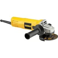
DWE4117 - Grinder DEWALT - Free user manual and instructions
Find the device manual for free DWE4117 DEWALT in PDF.


User questions about DWE4117 DEWALT
0 question about this device. Answer the ones you know or ask your own.
Ask a new question about this device
Download the instructions for your Grinder in PDF format for free! Find your manual DWE4117 - DEWALT and take your electronic device back in hand. On this page are published all the documents necessary for the use of your device. DWE4117 by DEWALT.
USER MANUAL DWE4117 DEWALT
English (original instructions) 23
natural_image
Icon of a person reading a book inside a black circle (no text or symbols)Fig. A
text_image
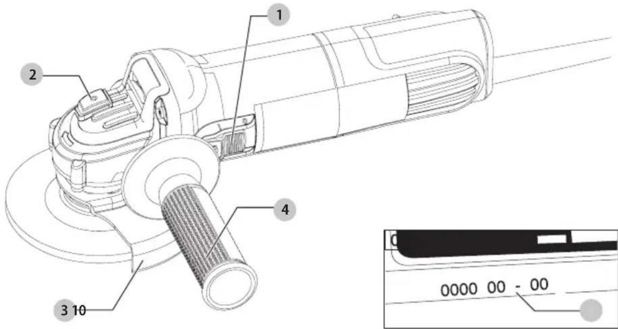
1 2 3 10 4 0 0000 00 - 00Fig. B
text_image
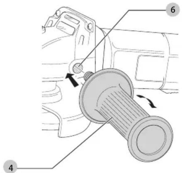
Technical diagram showing mechanical assembly with numbered parts and directional arrows indicating motion or movementFig. C
text_image
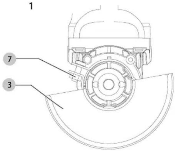
1 7 3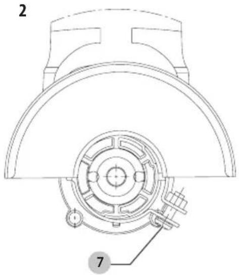
text_image
2 7Fig. D
text_image
Technical diagram of a mechanical assembly with numbered parts for identificationFig. E
text_image
Technical diagram of a mechanical component with numbered parts labeled 5, 8, 9, 11, and 13.Fig. F
text_image
4VINKELSLIBERE
DWE4016
Tillykke!
natural_image
Illustration of wooden logs and a gear mechanism (no text or symbols)natural_image
Illustration of wooden logs and a gear mechanism inside a circular frame (no text or symbols)You have chosen a DEWALT tool. Years of experience, thorough product development and innovation make DEWALT one of the most reliable partners for professional power tool users.
Technical Data
| DWE4016 DWE4117 | |||
| Voltage V | AC | 230 230 | |
| UK & Ireland V | AC | 230 230 | |
| Type 5 5 | |||
| Power output W 750 950 | |||
| Frequency Hz 50 50 | |||
| No-load/rated speed min | -1 | 11000 12000 | |
| Grinding wheel diameter | mm 115 125 | ||
| Grinding wheel thickness | mm | 6.4 | 6.4 |
| Cutting off wheel diameter | mm 115 | 125 | |
| Cutting off wheel thickness (max) | mm | 1.6 | 3 |
| Wheel type | 27 27 | ||
| Spindle diameter | M14 | M14 | |
| Weight | kg | 1.91 | 1.99 |
Noise values and/or vibration values (triax vector sum) according to EN62841-2-3:
| L_PA (emission sound pressure level) | dB(A) | 90 | 93 |
| L_WA (sound power level) | dB(A) | 98 | 101 |
| K (uncertainty for the given sound level) | dB(A) | 3 | 3 |
| Surface Grinding | |||
| Vibration emission value a_h, AG = | m/s2 | 7.6 | 7.7 |
| Uncertainty K = | m/s | 1.5 | 1.5 |
| Cutting off | |||
| Vibration emission value a_h, CO = | m/s2 | 6.6 | 6.6 |
| Uncertainty K = | m/s | 1.5 | 1.5 |
The vibration and/or noise emission level given in this information sheet has been measured in accordance with a standardised test given in EN62841 and may be used to compare one tool with another. It may be used for a preliminary assessment of exposure.
WARNING: The declared vibration and/or noise emission level represents the main applications of the tool. However, if the tool is used for different applications, with different accessories or is poorly maintained, the vibration and/or noise emission may differ. This may significantly increase the exposure level over the total working period. An estimation of the level of exposure to vibration and/or noise should also take into account the times when the tool is switched off or when it is running but not actually doing the job. This may significantly reduce the exposure level over the total working period.
Identify additional safety measures to protect the operator from the effects of vibration and/or noise such as: maintain the tool and the accessories, keep the hands warm (relevant for vibration), organisation of work patterns.
WARNING: Grinding thin sheets of metal or other easily vibrating structures with a large surface can result in a total noise emission much higher (up to 15 dB) than the declared noise emission values. Such workpieces should as far as possible be prevented from emitting sound by suitable measures such as the application of heavy flexible damping mats. The increased noise emission is also to be considered for both the risk assessment of noise exposure and selecting adequate hearing protection.
EC-Declaration of Conformity
Machinery Directive

Angle Grinders
DWE4016, DWE4117
DEWALT declares that these products described under
Technical Data are in compliance with:
2006/42/EC, EN62841-1:2015 +A11:2022 EN IEC 62841-2-3:2021 +A11:2021.
These products also comply with Directive 2014/30/EU and 2011/65/EU. For more information, please contact DEWALT at the following address or refer to the back of the manual.
The undersigned is responsible for compilation of the technical file and makes this declaration on behalf of DEWALT.

text_image
M. GeorgolMarkus Rompel
Vice-President Engineering, PTE-Europe
DEWALT, Richard-Klinger-Strasse 11,
65510, Idstein, Germany
12.20.2023
DECLARATION OF CONFORMITY
THE SUPPLY OF MACHINERY (SAFETY) REGULATIONS
2008

Angle Grinders
DWE4016, DWE4117
DEWALT declares that these products described under "technical data" are in compliance with:
The Supply of Machinery (Safety) Regulations, 2008, S.I. 2008/1597 (as amended),
EN62841-1:2015 +A11:2022 EN IEC 62841-2-3:2021 +A11:2021.
These products conform to the following UK Regulations:
Electromagnetic Compatibility Regulations, 2016, S.I.2016/1091 (as amended).
The Restriction of the Use of Certain Hazardous Substances in Electrical and Electronic Equipment Regulations 2012, S.I. 2012/3032 (as amended).
For more information, please contact DEWALT at the following address or refer to the back of the manual.
The undersigned is responsible for compilation of the technical file and makes this declaration on behalf of DEWALT.
Karl Evans
Vice President Professional Power Tools EANZ GTS
DEWALT UK, Meadowfield Avenue,
Spennymoor, DL16 6YJ,
United Kingdom
12.20.2023

WARNING: To reduce the risk of injury, read the instruction manual.
Definitions: Safety Guidelines
The definitions below describe the level of severity for each signal word. Please read the manual and pay attention to these symbols.
▲ANGER: Indicates an imminently hazardous situation which, if not avoided, will result in death or serious injury.
WARNING: Indicates a potentially hazardous situation which, if not avoided, could result in death or serious injury.
AUTION: Indicates a potentially hazardous situation which, if not avoided, may result in minor or moderate injury.
NOTICE: Indicates a practice not related to personal injury which, if not avoided, may result in property damage.
Denotes risk of electric shock.
▲ denotes risk of fire.
GENERAL POWER TOOL SAFETY WARNINGS
WARNING: Read all safety warnings, instructions, illustrations and specifications provided with this power tool. Failure to follow all instructions listed below may result in electric shock, fire and/or serious injury.
SAVE ALL WARNINGS AND INSTRUCTIONS FOR FUTURE REFERENCE
The term "power tool" in the warnings refers to your mains-operated (corded) power tool or battery-operated (cordless) power tool.
1) Work Area Safety
a) Keep work area clean and well lit. Cluttered or dark areas invite accidents.
b) Do not operate power tools in explosive atmospheres, such as in the presence of flammable liquids, gases or dust. Power tools create sparks which may ignite the dust or fumes.
c) Keep children and bystanders away while operating a power tool. Distractions can cause you to lose control.
2) Electrical Safety
a) Power tool plugs must match the outlet. Never modify the plug in any way. Do not use any adapter plugs with earthed (grounded) power tools. Unmodified plugs and matching outlets will reduce risk of electric shock.
b) Avoid body contact with earthed or grounded surfaces, such as pipes, radiators, ranges and refrigerators. There is an increased risk of electric shock if your body is earthed or grounded.
c) Do not expose power tools to rain or wet conditions. Water entering a power tool will increase the risk of electric shock.
d) Do not abuse the cord. Never use the cord for carrying, pulling or unplugging the power tool. Keep cord away from heat, oil, sharp edges or moving parts. Damaged or entangled cords increase the risk of electric shock.
e) When operating a power tool outdoors, use an extension cord suitable for outdoor use. Use of a cord suitable for outdoor use reduces the risk of electric shock.
f) If operating a power tool in a damp location is unavoidable, use a residual current device (RCD) protected supply. Use of an RCD reduces the risk of electric shock.
3) Personal Safety
a) Stay alert, watch what you are doing and use common sense when operating a power tool. Do not use a power tool while you are tired or under the influence of drugs, alcohol or medication. A moment of inattention while operating power tools may result in serious personal injury.
b) Use personal protective equipment. Always wear eye protection. Protective equipment such as a dust mask, non-skid safety shoes, hard hat or hearing protection used for appropriate conditions will reduce personal injuries.
c) Prevent unintentional starting. Ensure the switch is in the off position before connecting to power source and/or battery pack, picking up or carrying the tool. Carrying power tools with your finger on the switch or energising power tools that have the switch on invites accidents.
d) Remove any adjusting key or wrench before turning the power tool on. A wrench or a key left attached to a rotating part of the power tool may result in personal injury.
e) Do not overreach. Keep proper footing and balance at all times. This enables better control of the power tool in unexpected situations.
f) Dress properly. Do not wear loose clothing or jewellery. Keep your hair and clothing away from moving parts. Loose clothes, jewellery or long hair can be caught in moving parts.
g) If devices are provided for the connection of dust extraction and collection facilities, ensure these are connected and properly used. Use of dust collection can reduce dust-related hazards.
h) Do not let familiarity gained from frequent use of tools allow you to become complacent and ignore tool safety principles. A careless action can cause severe injury within a fraction of a second.
4) Power Tool Use and Care
a) Do not force the power tool. Use the correct power tool for your application. The correct power tool will do the job better and safer at the rate for which it was designed.
b) Do not use the power tool if the switch does not turn it on and off. Any power tool that cannot be controlled with the switch is dangerous and must be repaired.
c) Disconnect the plug from the power source and/or remove the battery pack, if detachable, from the power tool before making any adjustments, changing accessories, or storing power tools. Such preventive safety measures reduce the risk of starting the power tool accidentally.
d) Store idle power tools out of the reach of children and do not allow persons unfamiliar with the power tool or
these instructions to operate the power tool. Power tools are dangerous in the hands of untrained users.
e) Maintain power tools and accessories. Check for misalignment or binding of moving parts, breakage of parts and any other condition that may affect the power tool's operation. If damaged, have the power tool repaired before use. Many accidents are caused by poorly maintained power tools.
f) Keep cutting tools sharp and clean. Properly maintained cutting tools with sharp cutting edges are less likely to bind and are easier to control.
g) Use the power tool, accessories and tool bits, etc. in accordance with these instructions, taking into account the working conditions and the work to be performed. Use of the power tool for operations different from those intended could result in a hazardous situation.
h) Keep handles and grasping surfaces dry, clean and free from oil and grease. Slippery handles and grasping surfaces do not allow for safe handling and control of the tool in unexpected situations.
5) Service
a) Have your power tool serviced by a qualified repair person using only identical replacement parts. This will ensure that the safety of the power tool is maintained.
SAFETY INSTRUCTIONS FOR ALL OPERATIONS Safety Warnings Common for Grinding and Cutting-Off Operations
a) This power tool is intended to function as a grinder, or cut-off tool. Read all safety warnings, instructions, illustrations and specifications provided with this power tool. Failure to follow all instructions listed below may result in electric shock, fire and/or serious injury.
b) Operations such as sanding, wire brushing, polishing are not recommended to be performed with this power tool. Operations for which the power tool was not designed may create a hazard and cause personal injury.
c) Do not convert this power tool to operate in a way which is not specifically designed and specified by the tool manufacturer. Such a conversion may result in a loss of control and cause serious personal injury.
d) Do not use accessories which are not specifically designed and recommended by the tool manufacturer. Just because the accessory can be attached to your power tool, it does not assure safe operation.
e) The rated speed of the accessory must be at least equal to the maximum speed marked on the power tool. Accessories running faster than their rated speed can break and fly apart.
f) The outside diameter and the thickness of your accessory must be within the capacity rating of your power tool. Incorrectly sized accessories can not be adequately guarded or controlled.
g) The dimensions of the accessory mounting must fit the dimensions of the mounting hardware of the power tool. Accessories that do not match the mounting hardware of the power tool will run out of balance, vibrate excessively and may cause loss of control.
h) Do not use a damaged accessory. Before each use inspect the accessory such as abrasive wheel for chips and cracks, backing pad for cracks, tear or excess wear, wire brush for loose or cracked wires. If power tool or accessory is dropped, inspect for damage or install an undamaged accessory. After inspecting and installing an accessory, position yourself and bystanders away from the plane of the rotating accessory and run the power tool at maximum no-load speed for one minute. Damaged accessories will normally break apart during this test time.
i) Wear personal protective equipment. Depending on application, use face shield, safety goggles or safety glasses. As appropriate, wear dust mask, hearing protectors, gloves and workshop apron capable of stopping small abrasive or workpiece fragments. The eye protection must be capable of stopping flying debris generated by various operations. The dust mask or respirator must be capable of filtrating particles generated by your operation. Prolonged exposure to high intensity noise may cause hearing loss.
j) Keep bystanders a safe distance away from work area. Anyone entering the work area must wear personal protective equipment. Fragments of workpiece or of a broken accessory may fly away and cause injury beyond immediate area of operation.
k) Hold the power tool by insulated gripping surfaces only, when performing an operation where the cutting accessory may contact hidden wiring or its own cord. Cutting accessory contacting a "live" wire may make exposed metal parts of the power tool "live" and could give the operator an electrical shock.
1) Position the cord clear of the spinning accessory. If you lose control, the cord may be cut or snagged and your hand or arm may be pulled into the spinning accessory.
m) Never lay the power tool down until the accessory has come to a complete stop. The spinning accessory may grab the surface and pull the power tool out of your control.
n) Do not run the power tool while carrying it at your side. Accidental contact with the spinning accessory could snag your clothing, pulling the accessory into your body.
o) Regularly clean the power tool's air vents. The motor's fan will draw the dust inside the housing and excessive accumulation of powdered metal may cause electrical hazards.
p) Do not operate the power tool near flammable materials. Sparks could ignite these materials.
q) Do not use accessories that require liquid coolants. Using water or other liquid coolants may result in electrocution or shock.
FURTHER SAFETY INSTRUCTIONS FOR ALL OPERATIONS
Kickback and Related Warnings
Kickback is a sudden reaction to a pinched or snagged rotating wheel, backing pad, brush or any other accessory. Pinching or snagging causes rapid stalling of the rotating accessory which in turn causes the uncontrolled power tool to be forced in the direction opposite of the accessory's rotation at the point of the binding.
For example, if an abrasive wheel is snagged or pinched by the workpiece, the edge of the wheel that is entering into the pinch point can dig into the surface of the material causing the wheel
to climb out or kick out. The wheel may either jump toward or away from the operator, depending on direction of the wheel's movement at the point of pinching. Abrasive wheels may also break under these conditions.
Kickback is the result of tool misuse and/or incorrect operating procedures or conditions and can be avoided by taking proper precautions as given below:
a) Maintain a firm grip with both hands on the power tool and position your body and arms to allow you to resist kickback forces. Always use auxiliary handle, if provided, for maximum control over kickback or torque reaction during start up. The operator can control torque reaction or kickback forces, if proper precautions are taken.
b) Never place your hand near the rotating accessory. Accessory may kickback over your hand.
c) Do not position your body in the area where power tool will move if kickback occurs. Kickback will propel the tool in direction opposite to the wheel's movement at the point of snagging.
d) Use special care when working corners, sharp edges etc. Avoid bouncing and snagging the accessory. Corners, sharp edges or bouncing have a tendency to snag the rotating accessory and cause loss of control or kickback.
e) Do not attach a saw chain woodcarving blade, segmented diamond wheel with a peripheral gap greater than 10 mm or toothed saw blade. Such blades create frequent kickback and loss of control.
Safety Warnings Specific for Grinding and Cutting-Off Operations
a) Use only wheel types that are recommended for your power tool and the specific guard designed for the selected wheel. Wheels for which the power tool was not designed cannot be adequately guarded and are unsafe.
b) The grinding surface of centre depressed wheels must be mounted below the plane of the guard lip. An improperly mounted wheel that projects through the plane of the guard lip cannot be adequately protected.
c) The guard must be securely attached to the power tool and positioned for maximum safety, so the least amount of wheel is exposed towards the operator. The guard helps to protect the operator from broken wheel fragments, accidental contact with wheel and sparks that could ignite clothing.
d) Wheels must be used only for specified applications. For example: do not grind with the side of cut-off wheel. Abrasive cut-off wheels are intended for peripheral grinding, side forces applied to these wheels may cause them to shatter.
e) Always use undamaged wheel flanges that are of correct size and shape for your selected wheel. Proper wheel flanges support the wheel thus reducing the possibility of wheel breakage. Flanges for cut-off wheels may be different from grinding wheel flanges.
f) Do not use worn down wheels from larger power tools. A wheel intended for larger power tool is not suitable for the higher speed of a smaller tool and may burst.
g) When using dual purpose wheels always use the correct guard for the application being performed. Failure to use the correct guard may not provide the desired level of guarding, which could lead to serious injury.
Additional Safety Warnings Specific for Cutting-Off Operations
a) Do not "jam" the cut-off wheel or apply excessive pressure. Do not attempt to make an excessive depth of cut. Overstressing the wheel increases the loading and susceptibility to twisting or binding of the wheel in the cut and the possibility of kickback or wheel breakage.
b) Do not position your body in line with and behind the rotating wheel. When the wheel, at the point of operations, is moving away from your body, the possible kickback may propel the spinning wheel and the power tool directly at you.
c) When wheel is binding or when interrupting a cut for any reason, switch off the power tool and hold the power tool motionless until the wheel comes to a complete stop. Never attempt to remove the cut-off wheel from the cut while the wheel is in motion otherwise kickback may occur. Investigate and take corrective action to eliminate the cause of wheel binding.
d) Do not restart the cutting operation in the workpiece. Let the wheel reach full speed and carefully re-enter the cut. The wheel may bind, walk up or kickback if the power tool is restarted in the workpiece.
e) Support panels or any oversized workpiece to minimize the risk of wheel pinching and kickback. Large workpieces tend to sag under their own weight. Supports must be placed under the workpiece near the line of cut and near the edge of the workpiece on both sides of the wheel.
f) Use extra caution when making a "pocket cut" into existing walls or other blind areas. The protruding wheel may cut gas or water pipes, electrical wiring or objects that can cause kickback.
g) Do not attempt to do curved cutting. Overstressing the wheel increases the loading and susceptibility to twisting or binding of the wheel in the cut and the possibility of kickback or wheel breakage, which can lead to serious injury.
Residual Risks
In spite of the application of the relevant safety regulations and the implementation of safety devices, certain residual risks cannot be avoided. These are:
- Impairment of hearing.
- Risk of personal injury due to flying particles.
- Risk of burns due to accessories becoming hot during operation.
- Risk of personal injury due to prolonged use.
- Risk of dust from hazardous substances.
SAVE THESE INSTRUCTIONS
Electrical Safety
The electric motor has been designed for one voltage only. Always check that the power supply corresponds to the voltage on the rating plate.

Your DEWALT tool is double insulated in accordance with EN62841; therefore no earth wire is required.
WARNING: We recommend the use of a residual current device with a residual current rating of 30mA or less. This product is intended to be used with a safety transformer manufactured to BSEN61558 and BS4343. Never work without this transformer in place.
If the supply cord is damaged, it must be replaced only by DEWALT or an authorised service organisation.
Mains Plug Replacement (U.K. & Ireland Only)
If a new mains plug needs to be fitted:
• Safely dispose of the old plug.
- Connect the brown lead to the live terminal in the plug.
- Connect the blue lead to the neutral terminal.
WARNING: No connection is to be made to the earth terminal.
Follow the fitting instructions supplied with good quality plugs.
Recommended fuse: 13 A.
Using an Extension Cable
If an extension cable is required, use an approved 3-core extension cable suitable for the power input of this tool (refer to
Technical Data). The minimum conductor size is 1.5 mm^2 ; the maximum length is 30 m.
When using a cable reel, always unwind the cable completely.
Package Contents
The package contains:
1 Anglegrinder
1Guard
1Sidehandle
1Flangeset
1Hexkey
1 Instructionmanual
- Check for damage to the tool, parts or accessories which may have occurred during transport.
• Take the time to thoroughly read and understand this manual prior to operation.
Markings on Tool
The following pictograms are shown on the tool:

Read instruction manual before use.

Wear ear protection.

Wear eye protection.

Visible radiation. Do not stare into light.

Always operate with two hands.

Do not use the Type B guard for cut-off operations.
Date Code Position (Fig. A)
The production date code 10 consists of a 4-digit year followed by a 2-digit week and is extended by a 2-digit factory code.
Description (Fig. A)
WARNING: Never modify the power tool or any part of it.
Damage or personal injury could result.
1 On/off switch
2 Spindle lock button
3 Guard
4 Side handle
Intended Use
Your grinder has been designed for professional grinding and cutting applications.
DO nOT use under wet conditions or in the presence of flammable liquids or gases.
These heavy-duty angle grinders are professional power tools.
DO nOT let children come into contact with the tool.
Supervision is required when inexperienced operators use this tool.
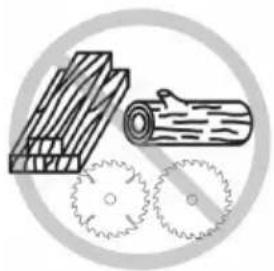
RANGER: Do not use for wood cutting or woodcarving. Do not use toothed blades of any kind. Serious injury can result.
- This product is not intended for use by persons (including children) suffering from diminished physical, sensory or mental abilities; lack of experience, knowledge or skills unless they are supervised by a person responsible for their safety. Children should never be left alone with this product.
Soft Start Feature
The soft start feature allows a slow speed build-up to avoid an initial jerk when starting. This feature is particularly useful when working in confined spaces.
No-Volt
The No-volt function stops the grinder restarting without the switch being cycled if there is a break in the power supply.
ASSEMBLY AND ADJUSTMENTS
WARNING: To reduce the risk of serious personal injury, turn tool off and disconnect tool from power source before making any adjustments or removing/installing attachments or accessories. An accidental start-up can cause injury.
Guards
AUTION: Guards must be used with all grinding wheels, cutting wheels, sanding flap discs, wire brushes, and wire wheels. Refer to Figure A to see guards provided with the unit. Some applications may require purchasing the correct guard from your local dealer or authorized service centre.
AUTION: When using a Type A (cut-off) wheel guard for facial grinding, the wheel guard may interfere with the workpiece causing poor control.
AUTION: When using a Type B (grinding) wheel guard for cutting-off operations with bonded abrasive wheels, there is an increased risk of exposure to emitted sparks and particles, as well as exposure to wheel fragments in the event of wheel burst.
AUTION: When using a Type A (cut-off), Type B (grinding) wheel guard for cutting-off and facial operations in concrete or masonry, there is an increased risk of exposure to dust and loss of control resulting in kickback.
nOTE: Edge grinding and cutting can be performed with Type 27 wheels designed and specified for this purpose; 6 mm thick wheels are designed for surface grinding while thinner Type 27 wheels need to be examined for the manufacturer's label to see if they can be used for surface grinding or only edge grinding/cutting. A Type A (cut-off) wheel guard must be used for any wheel where surface grinding is forbidden. A Type A (cut-off) (previously called type 1/41) wheel guard must be used for any dual purpose (combined grinding and cutting-off
abrasive) wheels. Cutting can also be performed by using a Type 1/41 wheel and a Type A cut-off wheel guard previously called Type 1/41 guard.
nOTE: See the Accessory and Guard Applications Chart to select the proper guard / accessory combination.
Attaching Side Handle (Fig. B)
WARNING: Before using the tool, check that the handle is tightened securely.
WARNING: The side handle should always be used to maintain control of the tool at all times. Screw the side handle 4 tightly into one of the holes 6 on either side of the gear case.
Mounting and Removing the Guard (Fig. C)
AUTION: Guards must be used with this grinder.
To Mount the Guard
- Place the angle grinder on a table, spindle up.
- Press the guard 3 down (Fig. C1).
- Position the guard between your body and workpiece.
- Tight the screw 7 holding the cinch collar firmly around the neck of spindle (Fig. C2).
To Remove the Guard
- Loosen the screw 7 holding the cinch collar around the neck of the spindle.
- Lift up on the guard.
Fitting and Removing a Grinding Disc (Fig. A, D, E)
WARNING: Do not use a damaged disc.
- Place the tool on a table, guard up.
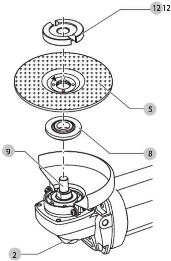
- Fit the backing flange 8 correctly onto the spindle 9 (Fig. D).
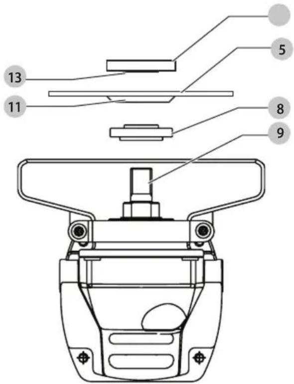
- Place the disc 5 on the flange 8. When fitting a disc with a raised centre, make sure that the raised centre 11 is facing the flange 8.
- Screw the outer flange 12 onto the spindle 9 (Fig. E). The ring on the flange 13 must face towards the disc when fitting a grinding disc.
- Press the spindle lock button 2 and rotate the spindle 9 until it locks in position.
- Tighten the flange 12 with the provided hex wrench.
- Release the spindle lock.
- To remove the disc, loosen the flange 12 with the provided hex wrench.
Prior to Operation
• Install the guard and appropriate disc or wheel. Do not use excessively worn discs or wheels.
- Be sure the inner and outer flange are mounted correctly. Follow the instructions given in the Accessory and Guard Applications Chart.
- Make sure the disc or wheel rotates in the direction of the arrows on the accessory and the tool.
OPERATION
Instructions for Use
WARNING: Always observe the safety instructions and applicable regulations.
WARNING: To reduce the risk of serious personal injury, turn tool off and disconnect tool from power source
before making any adjustments or removing/installing attachments or accessories. An accidental start-up can cause injury.
WARNING:
- Ensure all materials to be ground or cut are secured in place.
- Secure and support the workpiece. Use clamps or a vise to hold and support the workpiece to a stable platform. It is important to clamp and support the workpiece securely to prevent movement of the workpiece and loss of control. Movement of the workpiece or loss of control may create a hazard and cause personal injury.
- Support panels or any oversized workpiece to minimize the risk of wheel pinching and kickback. Large workpieces tend to sag under their own weight. Supports must be placed under the workpiece near the line of cut and near the edge of the workpiece on both sides of the wheel.
• Always wear regular working gloves while operating this tool.
• The gear becomes very hot during use. - Apply only a gentle pressure to the tool. Do not exert side pressure on the disc.
• Always install the guard and appropriate disc or wheel. Do not use excessively worn disc or wheel. - Be sure the inner and outer flange are mounted correctly.
• Make sure the disc or wheel rotates in the direction of the arrows on the accessory and the tool. - Avoid overloading. Should the tool become hot, let it run a few minutes under no load condition to cool the accessory. Do not touch accessories before they have cooled. The discs become very hot during use.
- Never work with the grinding cup without a suitable protection guard in place.
- Do not use the power tool with a cut-off stand.
- Never use blotters together with bonded abrasive products.
- Be aware, the wheel continues to rotate after the tool is switched off.
Proper Hand Position (Fig. F)
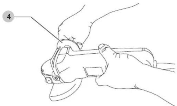
WARNING: To reduce the risk of serious personal injury, ALWAYS use proper hand position as shown.
WARNING: To reduce the risk of serious personal injury, ALWAYS hold securely in anticipation of a sudden reaction. Proper hand position requires one hand on the side handle 4, with the other hand on the body of the tool, as shown in Fig. F.
Switches
WARNING: Do not switch the tool on or off when under load.
WARNING: Before using the tool, check that the handle is tightened securely.
Slider Switch (Fig. A)
To start the tool, slide the on/off slider switch 1 toward the front of the tool. To stop the tool, release the on/off slider switch.
For continuous operation, slide the switch toward the front of the tool and press the forward part of the switch inward.
To stop the tool while operating in continuous mode, press the rear part of the slider switch and release.
Spindle Lock (Fig. A)
The spindle lock 2 is provided to prevent the spindle from rotating when installing or removing wheels. Operate the spindle lock only when the tool is turned off, unplugged from the power supply, and has come to a complete stop.
NOTICE: To reduce the risk of damage to the tool, do not engage the spindle lock while the tool is operating. Damage to the tool will result and attached accessory may spin off possibly resulting in injury.
To engage the lock, depress the spindle lock button and rotate the spindle until you are unable to rotate the spindle further.
Metal Applications
When using the tool in metal applications, make sure that a residual current device (RCD) has been inserted to avoid residual risks caused by metal swarf.
If the power supply is shut off by the RCD, take the tool to an authorised DEWALT repair agent.
WARNING: In extreme working conditions, conductive dust can accumulate inside the machine housing when working with metal. This can result in the protective insulation in the machine becoming degraded with a potential risk of an electrical shock. To avoid build-up of metal swarf inside the machine, we recommend to clear the ventilation slots on a daily basis. Refer to Maintenance.
Using Flap Discs
WARNING: Metal dust build-up. Extensive use of flap discs in metal applications can result in the increased potential for electric shock. To reduce this risk, insert an RCD before use and clean the ventilation slots daily by blowing dry compressed air into the ventilation slots in accordance with the below maintenance instructions.
MAINTENANCE
Your power tool has been designed to operate over a long period of time with a minimum of maintenance. Continuous satisfactory operation depends upon proper tool care and regular cleaning.
WARNING: To reduce the risk of serious personal injury, turn tool off and disconnect tool from power source before making any adjustments or removing/installing attachments or accessories. An accidental start-up can cause injury.
Pop-off Brushes
The motor will be automatically shut off indicating that the carbon brushes are nearly worn out and that the tool needs servicing. The carbon brushes are not user-serviceable. Take the tool to an authorised DEWALT repair agent.
Lubrication
Your power tool requires no additional lubrication.
Cleaning
WARNING: Electrical shock and mechanical hazard. Disconnect the electrical appliance from the power source before cleaning.
WARNING: To ensure safe and efficient operation, always keep the electrical appliance and the ventilation slots clean.
WARNING: Never use solvents or other harsh chemicals for cleaning the non-metallic parts of the tool. These chemicals may weaken the materials used in these parts. Use a cloth dampened only with water and mild soap. Never let any liquid get inside the tool; never immerse any part of the tool into a liquid.
Ventilation slots can be cleaned using a dry, soft non-metallic brush and/or a suitable vacuum cleaner. Do not use water or any cleaning solutions. Wear approved eye protection and an approved dust mask.
Optional Accessories
WARNING: Since accessories, other than those offered by DEWALT, have not been tested with this product, use of such accessories with this tool could be hazardous. To reduce the risk of injury, only DEWALT recommended accessories should be used with this product.
WARNING: Do not use a bonded abrasive wheel that is past its expiration (EXP) date as marked near center of wheel (if provided). Expired wheels are more likely to burst and cause serious injury. Store bonded abrasive wheels in dry location without temperature or humidity extremes. Destroy expired or damaged wheels so they cannot be used. Consult your dealer for further information on the appropriate accessories.
Protecting the Environment

Separate collection. Products marked with this symbol must not be disposed of with normal household waste.
Products contain materials that can be recovered or recycled, reducing the demand for raw materials. Please recycle electrical products according to local provisions. Further information is available at www.2helpU.com.
Additional Information for Guards and Accessories for DWE4016, DWE4117
| When using segmented diamond wheels, use only diamond wheels with a peripheral gap not greater than 10 mm and negative rake angle. | 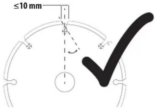 |
| DO NOT USEsegmented diamond wheels with a peripheral gap greater than 10 mm and/or a a positive rake angle. | 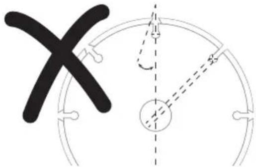 |
| For all grinding, sanding, and wheel type wire brushing accessories, the lowest portion of the accessory must be contained within the guard enclosure with 2mm or greater clearance to the bottom lip of guard. | ≥2 mm |
DANGER: Do not use for wood cutting or woodcarving. Do not use toothed blades of any kind. Serious injury can result.
natural_image
Illustration of wood grain and a log with two circular insets showing gear-like structures (no text or symbols)| Accessory and Guard Applications Chart | |||
| Guard Type Accessory Description How to Fit Grinder | |||
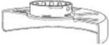 Type BGuard Type BGuard |  | Depressed centre grinding disc | 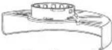 Type B guard Type B guard Backing flange Backing flange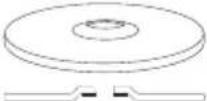 Type 27 depressed centre wheel Type 27 depressed centre wheel Threaded clamp nut Threaded clamp nut |
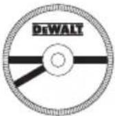 | Flap wheel | ||
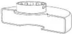 Type AGuard Type AGuard | 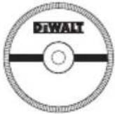 | Masonry cutting disc, bonded | 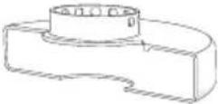 Type A guard Type A guard Backing flange Backing flange |
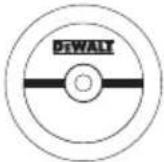 | Metal cutting disc, bonded | ||
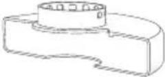 Type AGuardOR Type AGuardOR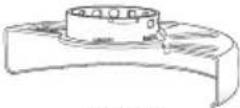 Type BGuard Type BGuard | 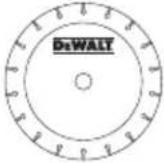 | Diamond cutting wheels | 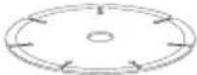 Cutting wheel Cutting wheel Threaded clamp nut Threaded clamp nut |
AMOLADORAS ANGULARES DWE4016, DWE4117
¡Enhorabuena!
natural_image
Illustration of wooden logs and a gear mechanism (no text or symbols)natural_image
Illustration of wooden logs and a gear mechanism (no text or symbols)Vice-Presidente Engineering, PTE-Europe
DEWALT, Richard-Klinger-Strasse 11,
65510, Idstein, Germania
12.20.2023

natural_image
Illustration of wooden logs and a gear mechanism (no text or symbols)Vice-President Engineering, PTE-Europe
DEWALT, Richard-Klinger-Strasse 11,
BEWAAR ALLE WAARSCHUWINGEN EN INSTRUCTIES ALS TOEKOMSTIG REFERENTIEMATERIAAL
natural_image
Illustration of wood logs and a wooden log with gear-like patterns (no text or symbols)Vice-President Engineering, PTE-Europe
DEWALT, Richard-Klinger-Strasse 11,
65510, Idstein, Tyskland
12.20.2023

natural_image
Illustration of wood grain and a cylindrical log with two gear-like circular insets (no text or symbols)| Tabellen Bruk av tilbehør og beskyttelser | |||
| Beskyttelsestype Tilbehør Beskrivelse Slik monterer du sliperen | |||
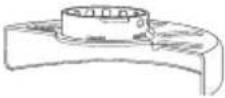 Type B beskyttelse Type B beskyttelse | 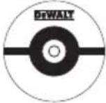 | Slipeskive med forsenket senter | 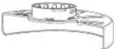 Type B beskyttelse Type B beskyttelse  Bakre flens Bakre flens Type 27 forsenket senterskive Type 27 forsenket senterskive  Gjenget festemutter Gjenget festemutter |
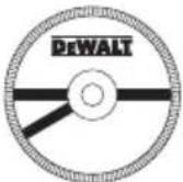 | Lamellskive | ||
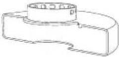 Type A Beskyttelse Type A Beskyttelse | 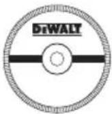 | Murkappeskive, limt | 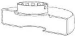 Type A beskyttelse Type A beskyttelse Bakre flens Bakre flens |
 | Metall-kappeskive, limt | ||
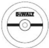
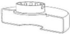 Type A BeskyttelseELLERType B beskyttelse Type A BeskyttelseELLERType B beskyttelse | 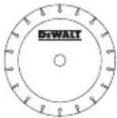 | Diamantkutteskiver | 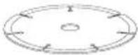 Kutteskive Kutteskive Gjenget festemutter Gjenget festemutter |
REBARBADORAS ANGULARES
DWE4016, DWE4117
Gratulerer!
text_image
Mr. GeorgolMarkus Rompel
Vice-Presidente de Engenharia, PTE-Europe DEWALT, Richard-Klinger-Strasse 11, 65510, Idstein, Alemanha 12.20.2023

natural_image
Illustration of wooden logs and a gear mechanism (no text or symbols)natural_image
Illustration of wood grain and a rolled log inside a circular frame (no text or symbols)Vinkelslipar DWE4016, DWE4117
DEWALT intygar att dessa produkter, beskrivna under Tekniska data uppfyller: 2006/42/EG, EN62841-1:2015 +A11:2022 EN IEC 62841-2-3:2021 +A11:2021.
natural_image
Illustration of wood grain and a rolled log inside a circular frame (no text or symbols)SVENSKA