
302697 - Multimeter Brandson - Free user manual and instructions
Find the device manual for free 302697 Brandson in PDF.


| Product type | Digital multimeter |
| Brand | Brandson |
| Model | 302697 |
| Power supply | 2 AAA 1.5 V batteries |
| Display | 3 1/2 digits |
| DC voltage | 200 mV to 600 V |
| AC voltage | 200 mV to 600 V |
| DC current | 2000 μA to 10 A |
| Resistance | 200 Ω to 2000 kΩ |
| Diode test | Yes |
| Continuity test | Yes, audible signal <30 Ω |
| Temperature measurement | -20°C to 300°C (K-type probe) |
| Transistor test (hFE) | Yes |
| Overload protection | Fuse F500 mA/600 V and F10 A/600 V |
| Measurement category | CAT II 600 V |
| Safety | Detailed instructions in the manual |
| Maintenance | Soft cloth, no solvents |
| Cleaning | Dry soft cloth |
| Included parts | 2 test leads, transistor probe, temperature sensor |
| Use | Indoors only |
| Operating temperature | 0°C to 40°C |
| Storage temperature | -10°C to 50°C |
| Humidity | <80% operating, <85% storage |
Frequently Asked Questions - 302697 Brandson
User questions about 302697 Brandson
0 question about this device. Answer the ones you know or ask your own.
Ask a new question about this device
Download the instructions for your Multimeter in PDF format for free! Find your manual 302697 - Brandson and take your electronic device back in hand. On this page are published all the documents necessary for the use of your device. 302697 by Brandson.
USER MANUAL 302697 Brandson
Strom (DC Current A---
Thank you for choosing a Brandon product. Please read the following user manual carefully so as to have an enjoyable experience with your purchased product.
1 Scope of supply
- Multimeter
- 2 measuring cables (1 black, 1 red)
- Transistor measuring adapter
- Temperature sensor
- User manual
2 Technical data
| Power supply 2 AAA batteries | 1.5V |
| Operating temperature 0°C - | 40°C / < 80% humidity |
| Storage temperature -10°C - | 50°C / < 85% humidity |
| Display 3 1/2 digits | |
| Sampling interval Twice in a second | |
| Overvoltage protection 220V | for 200mV resolution; 600V AC/DC for all resolutions |

CAUTION! PLEASE NOTE!
3 Important safety instructions for this device
- Before using the device, check the housing and all the parts that are used with the measuring device. Do not use this device if you detect any damage, such as a housing part is missing. Be especially careful if there are children or pets in you household.
- Check the measuring leads for damaged insulation or exposed metal. And also check it for continuity.
-
Please do not apply more than the rated voltage, as specified on the device, to the terminals or between the terminal and ground.
-
The rotary switch should be in the correct position. The measuring range should not be changed when the device is being used for measurement.
- If the device is being used for high voltages, special care should be taken as there is a risk of electric shock!
- Use the correct terminals and functions for your measurements.
- Do not use or keep the device in surroundings where the temperature or humidity is high. Do not keep it near explosive or inflammable substances, nor in the vicinity of strong magnetic fields. The performance of the device may deteriorate if it becomes humid.
- When using the measuring leads, keep your fingers behind the finger guard!
- Disconnect the power supply and discharge all high-voltage capacitors before checking the resistance, continuity, diodes or hFE.
- Replace the batteries as soon as the battery indicator appears in the display. The device may show incorrect readings if the batteries are weak, which may result in electric shock or other physical injuries!
- The measuring device is suitable for indoor use only!
- Switch off the measuring device when it is not being used and remove the batteries if the device is not used for a long period of time. Constantly check the batteries if the device is being used for a long time. Replace the batteries as soon as you detect any defect.
4 Appropriate use
- Measuring and displaying the electric parameters in the range of category II up to a max. of 600V (in accordance with EN 61010-1 and all the lower categories)
- Measuring DC and AC voltage up to a max. of 600V DC/AC
- Measuring DC current up to 10 A
- Measuring resistance up to 2M
- Diode testing
- Continuity testing (a beep is heard for < 30
- Temperature measurement from 20 to +300^ (with the provided temperature sensor)
The measurement functions and ranges can be selected using the rotary switch. The measuring range is selected automatically for the diode testing, continuity testing and transistor testing functions. The two current measuring inputs are protected against overload. The voltage in the measuring circuit should not exceed 600V in CAT II. And both current measuring ranges are protected using high-performance ceramic fuses. The multimeter works with two 1.5V AAA batteries.
The device should be operated only with the specified type of battery. Please do not use rechargeable batteries. There may be measurement errors due to the low voltage. The multimeter should not be operated in open condition, with the battery compartment open or without the battery compartment cover. The battery compartment is protected by a lock screw. Ensure that the screw is tightened again after replacing the battery or after opening the battery compartment. Measurements should not be carried out in damp rooms or under unfavourable ambient conditions. Unfavourable ambient conditions include for example:
- High humidity, wetness, dust, fumes or solvents, flammable gases, storms or stormy conditions such as strong electrostatic fields, etc.
Please use only the measurement leads or accessories which match the specifications of the device for the measurements. Any use other than those described above may damage the product. In addition, this is associated with significant and avoidable risks, such as short-circuit, fire, electric shock, etc. The complete product should be not modified or altered! Read the user manual very carefully and keep it safely for future reference. The safety instructions are very important and should be followed in all cases.
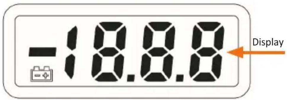
5 Product details
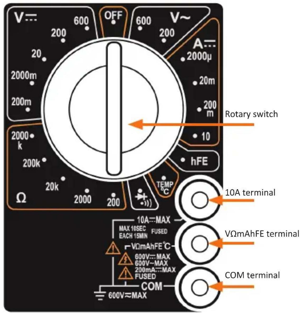
5.1 Resolution and accuracy
Direct current (DC voltage V=
| Setting range Resolution | lution Accuracy | |
| 200mV 100μV ± 0.5% | ||
| 2000mV 1mV | ± 0.8%20V 10mV | |
| 200V 100mV | ||
| 600V 1V ± 1.0% |
Alternating current(AC voltage
| Setting range Resolution | Resolution Accuracy | |
| 200V 100mV | ± 2.0% | |
| 600V 1V |
Current (DC current A
| Setting range Resolution | lution Accuracy | |
| 2000μA 1μA | ± 1.8% | |
| 20mA 10μA | ||
| 200mA 100μA ± 2.0% | ||
| 10A 10mA ± 2.0% |
Overload protection: F500mA / 600V and F10A / 600V fuse
Resistance
| Setting range Resolution | lution Accuracy | |
| 200Ω 0.1 Ω ± 1.0 % | ||
| 2000Ω 1 Ω | ± 1.0 % | |
| 20kΩ 10 Ω | ||
| 200kΩ 100 Ω | ||
| 2000kΩ 1 kΩ |
Maximum open circuit voltage: 3V; Overload protection: 15 seconds max 220Vrms
Temperature (with K-type temperature sensor)
| Setting range Resolution | lution Accuracy | |
| 20°C to 150°C | 1°C | ± 1.0 % |
| 150°C to 300°C ± 1.5 % |
6 Initial use and operation
Take the device out of the package and remove all packaging material. A battery compartment, which is secured by a screw, is located at the back of the device. Remove the screw, open the battery compartment and insert two 1.5V AAA batteries. Make sure the polarity of the contacts is correct. Then close the battery compartment.
Note: Please use only 1.5V AAA batteries and not rechargeable batteries, since a low voltage of 1.2V may result in device malfunction!
Measurements
Ensure that only the required measuring leads are connected to the device. Remove any measuring leads that are not needed for safety reasons. Measurements in circuits with a possible voltage of more than 50V AC and more than 75V DC should be carried out only by technicians or trained personnel who are familiar with the regulations and the resulting dangers.

Never exceed the maximum permissible input parameters. Do not touch any circuit parts or circuits if they are carrying high voltages (higher than 25V ACrms or 35V DC)! Before measuring, check the measuring leads for any damage. Faulty measuring leads should not be used under any circumstances! Possible danger to life!
Voltage measurement DC (direct current) & AC (alternating current)
- Connect the red measuring lead to the "VΩmAhFE" terminal and the black measuring lead to the "COM" terminal.
- Set the range to the desired voltage position. If the voltage to be measured is not known, then set the rotary switch to the highest range (in this case, 600V) and reduce it until a satisfactory reading is shown in the display.
- Connect the measuring leads to the desired measurement points
- Switch on the power supply of the device or the circuit to be measured. The voltage reading is shown on the digital display along with the voltage polarity.
DC current measurement
- Connect the red measuring lead to the "VΩmAhFE" terminal and the black measuring lead to the "COM" terminal. Connect the red measuring lead to the "10A" terminal for measurements between 200mA and 10A.
- Set the range to the desired DC current position.
- Open the circuit to be measured and measure in series with the load using the measuring leads.
- The actual current reading is shown in the digital display.

Caution! Note: The "10A" function is designed for intermittent use only.
The maximum contact time of the measuring leads with the circuit is 10 seconds, with a minimum gap of 15 minutes between measurements.
Resistance measurement
- Connect the red measuring lead to the "VΩmAhFE" terminal and the black measuring lead to the "COM" terminal.
- Set the rotary selector to the desired range () .
- If the resistance being measured is connected to a circuit, turn off the power supply and discharge all the capacitors before measurement.
- Connect the measuring leads to the circuit to be measured.
- The measured resistance is shown on the digital display.
Continuity measurement of diode (DIODE measurement)
- Connect the red measuring lead to the "VΩmAhFE" terminal and the black measuring lead to the "COM" terminal.
- Set the rotary switch to " " position.
- Connect the red measuring lead to the anode of the diode and the black measuring lead to the cathode.
- The forward voltage drop in mV is shown in the display. If the diode is measured the other way round, then "1" is shown in the display.
Transistor measurement (hFE transistor measurement)
- Set the rotary switch to "hFE" position
- Insert the transistor measuring adapter into the terminals COM (-) and "VΩmAhFE" (+). Ensure that the "COM" terminal of the adaptor matches the "COM" terminal of the device.
- Determine whether the transistor is PNP or NPN type and locate the emitter, base and collector leads. Insert the cable (terminals) directly into the hFE socket on the adapter. Pay attention to the correct polarity of the contacts.
- The digital display shows the approximate hFE value under the condition of base current 10 A and VCE 2.8V.
Temperature measurement
- Set the rotary switch to "TEMP °C" position.
- Connect the K-type temperature sensor to the COM (black) and "VΩmAh-FE" (red) terminals.
- The actual temperature measured by the temperature sensor is shown in the display
Note: The thermocouple provided has a maximum operating probe temperature of 250^ / 482^ (300°C/572°C for short durations). The sensor provided along with the device is a very fast reacting thermocouple, which is suitable for many general applications.
Audible continuity test
- Connect the red measuring lead to the "VΩmAhFE" terminal and the black measuring lead to the "COM" terminal.
- Set the rotary switch to " " position
- Then connect the measuring leads to the two desired points in the circuit to carry out a continuity test. If the resistance is less than 30 ( ± 20 ), a beeping sound is heard.
7 Replacing the battery or fuse
The fuse does not have to be replaced normally. If it is faulty, then this is usually due to operating error.
In such cases, replace the fuse (F500mA / 600V for the mA terminal and F10A / 600V for 10A terminal), remove the 3 screws at the bottom of the housing. There is a screw under the battery compartment. Open the housing and then remove the old fuse and replace it with a new one. Pay special attention to the correct polarity.
Note: Always ensure that the replaced fuse is of the same type and has the same values.
Please replace the batteries as soon as the display becomes dim or the battery icon appears in the display.
8 Cleaning and maintenance
Clean the surface of the device with a soft cloth and a mild cleaning agent only. Never use scouring agents or solvents so as to prevent damage. Never immerse the device under water and always keep it dry.

9 Safety instructions and liability disclaimer
Never try to open the device to carry out repairs or conversions. Avoid contact with mains voltages. Do not short-circuit the product. The device is not certified for use in the open air; only use it in dry conditions. Protect it from high humidity, water and snow. Keep it away from high temperatures. Do not subject the device to sudden changes in temperature or heavy vibration as this might damage electronic components.
Examine the device for damage before using it. The unit should not be used if it has received an impact or has been damaged in any other way. Please observe national regulations and restrictions. Do not use the device for purposes other than those described in the instructions. This product is not a toy. Keep it out of the reach of children or mentally impaired persons. Any repair or alteration to the device not carried out by the original supplier, will invalidate the warranty or guarantee.
The product may only be used by persons who have read and understood these instructions. The device specifications may change without any separate prior notice to this effect.

10 Disposal instructions
Electrical and electronic devices may only be disposed of in accordance with the European WEEE Directive and not with household rubbish. Components must be disposed of or recycled separately as dangerous, toxic elements can inflict sustained damage on the environment if they are disposed of incorrectly.
As a consumer, you are bound by the Electrical and Electronic Devices Act (ElektroG) to return electrical and electronic goods free of charge at the end of their useful life to the manufacturer, the place of purchase or to specially set up, public collection points.
The details in each case are governed by national law. The symbol on the product, the operating instructions and/or the packaging refers to these regulations. By separating materials in this way, recycling and disposing of old devices, you are making an important contribution towards protecting our environment.

11 Instructions on the disposal of batteries
With regard to the sale of batteries or the supply of devices containing batteries, the supplier is obliged to draw the customer's attention to the following:
As the end user, the customer has a statutory obligation to return used batteries. He can return old batteries stocked or previously stocked by the supplier in the form of new batteries to the supplier's despatch warehouse (despatch address) free of charge. The symbols shown on the batteries have the following meanings: Pb = battery contains more than 0.004 percent by mass of lead, Cd = battery contains more than 0.002 percent by mass of cadmium, Hg = battery contains more than 0.0005 percent by mass of quicksilver.

The symbol of the rubbish bin with a cross through it indicates that the battery may not be put in household waste.

WEEE guideline: 2012/19/EU
WEEE register number: DE 67896761
WD Plus GmbH, herewith declares that this product 302697/20171013XM003 conforms to the principle requirements and other relevant stipulations. The complete Declaration of Conformity can be obtained from: WD Plus GmbH, Wohlenbergstraße 16, 30179 Hanover
Tension continue (DC Voltage V...
| Plage de réglage Résolution Précision | |
| 200 mV 100 μV ± 0,5% | |
| 200 0mV 1 mV | |
| ± 0,8%20 V 10 mV | |
| 200 V 100 mV | |
| 600 V 1 V ± 1,0% |
Tension alternative (AC Voltage V~
Courant (DC Current A---
Mesure de courant continu (DC Current Measurement)
Corrente (DC Current A---
| Range Risoluzione Precisione | |
| 2000μA 1μA | |
| 20mA | 10μA |
| 200mA 100μA ± 2,0% | |
| 10A 10mA | ± 2,0% |
Corriente (DC current A:
| Ajustes Resolutiún Precisión | |
| 2000 μA 1 μA | |
| 20 mA 10 μA | |
| 200 mA 100 μA ± 2,0% | |
| 10 A | 10 mA |
- Strom (DC Current A---
- Scope of supply
- Technical data
- CAUTION! PLEASE NOTE!
- Important safety instructions for this device
- Appropriate use
- Resolution and accuracy
- Initial use and operation
- Measurements
- Voltage measurement DC (direct current) & AC (alternating current)
- DC current measurement
- Resistance measurement
- Continuity measurement of diode (DIODE measurement)
- Transistor measurement (hFE transistor measurement)
- Temperature measurement
- Audible continuity test
- Replacing the battery or fuse
- Cleaning and maintenance
- Safety instructions and liability disclaimer
- Disposal instructions
- Instructions on the disposal of batteries
- Mesure de courant continu (DC Current Measurement)
- Corriente (DC current A:
Brand : Brandson
Model : 302697
Category : Multimeter