Thea - Baby products Lionelo - Free user manual and instructions
Find the device manual for free Thea Lionelo in PDF.

| Product type | Baby safety gate |
| Brand | Lionelo |
| Model | Thea |
| Opening width | 70 cm to 140 cm |
| Maximum baseboard height | 12 cm |
| Recommended age | Up to 24 months |
| Safety standard | EN 1930:2011 |
| Locking system | Manual with buttons and lock indicator (green/red) |
| Correct installation indicator | Yes, green light |
| Material | Metal and plastic |
| Estimated weight | Approximately 3.5 kg |
| Use | Indoor: door openings, top or bottom of stairs |
| Mounting | Wall-mounted with screws and wall plugs (included) |
| Supplied parts | Wall brackets, extension brackets, adhesive tapes, screws, wall plugs |
| Maintenance | Clean with a damp cloth and mild detergent |
| Surface compatibility | Wood, concrete, tile (with appropriate wall plugs) |
| Warranty | Not specified, contact the manufacturer |
| Manufacturer | BrandLine Group Sp. z o. o. |
Frequently Asked Questions - Thea Lionelo
User questions about Thea Lionelo
0 question about this device. Answer the ones you know or ask your own.
Ask a new question about this device
Download the instructions for your Baby products in PDF format for free! Find your manual Thea - Lionelo and take your electronic device back in hand. On this page are published all the documents necessary for the use of your device. Thea by Lionelo.
USER MANUAL Thea Lionelo
natural_image
Pure technical line drawing of a vertical mechanical or architectural component without any text, numbers, or symbols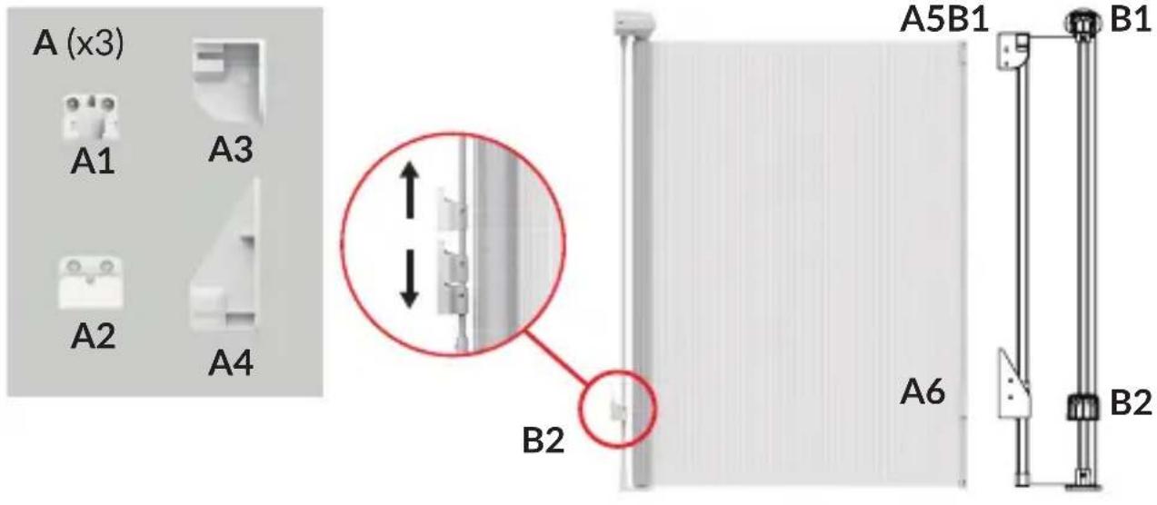
A
natural_image
Exterior view of a modern concrete staircase with four horizontal steps, mounted on a white wall (no signage or text visible)1
natural_image
Exterior view of a modern office building (no signage)2
natural_image
Exterior view of a modern office building (no signage)3
natural_image
Exterior view of a modern office building (no signage)4
B
C
flowchart
graph TD
    A["Start"] --> B{Check}
    B -->|✓| C["Process Step 1"]
    B -->|×| D["Process Step 2"]
    C --> E["Check Point 1"]
    D --> F["Check Point 2"]
    E --> G["End"]
    F --> H["End"]

natural_image
Exterior view of a white cylindrical wall fixture with a red circle highlighting a small component, and an inset close-up showing the same fixture (no text or symbols visible)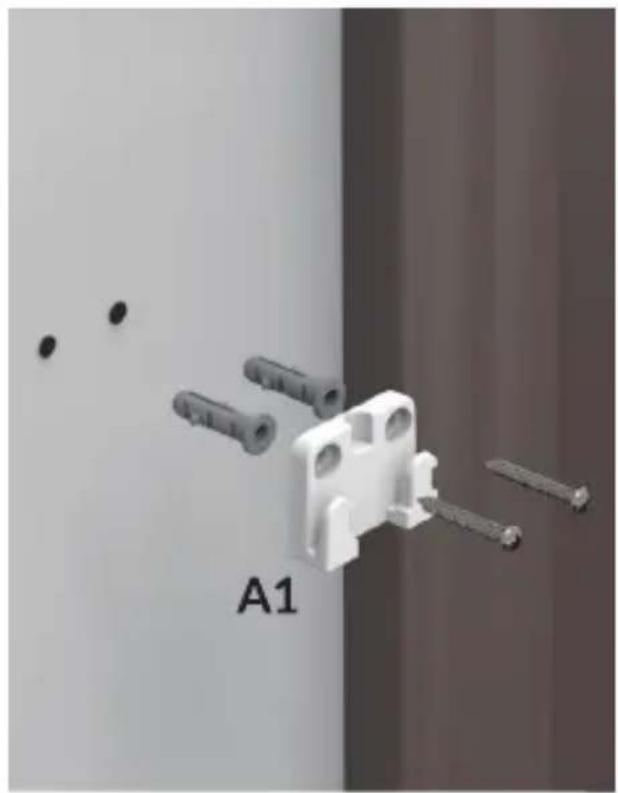
natural_image
3D rendering of a white plastic component with multiple screws and pins, labeled A1 (no text or symbols on the object itself)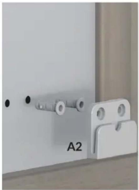
natural_image
Close-up of a white metal latch with a labeled component 'A2' and two circular holes, mounted on a wooden surface (no other text or symbols visible)5

6

natural_image
Exterior view of a white refrigerator with attached electrical outlets and a close-up of the front panel (no text or symbols visible)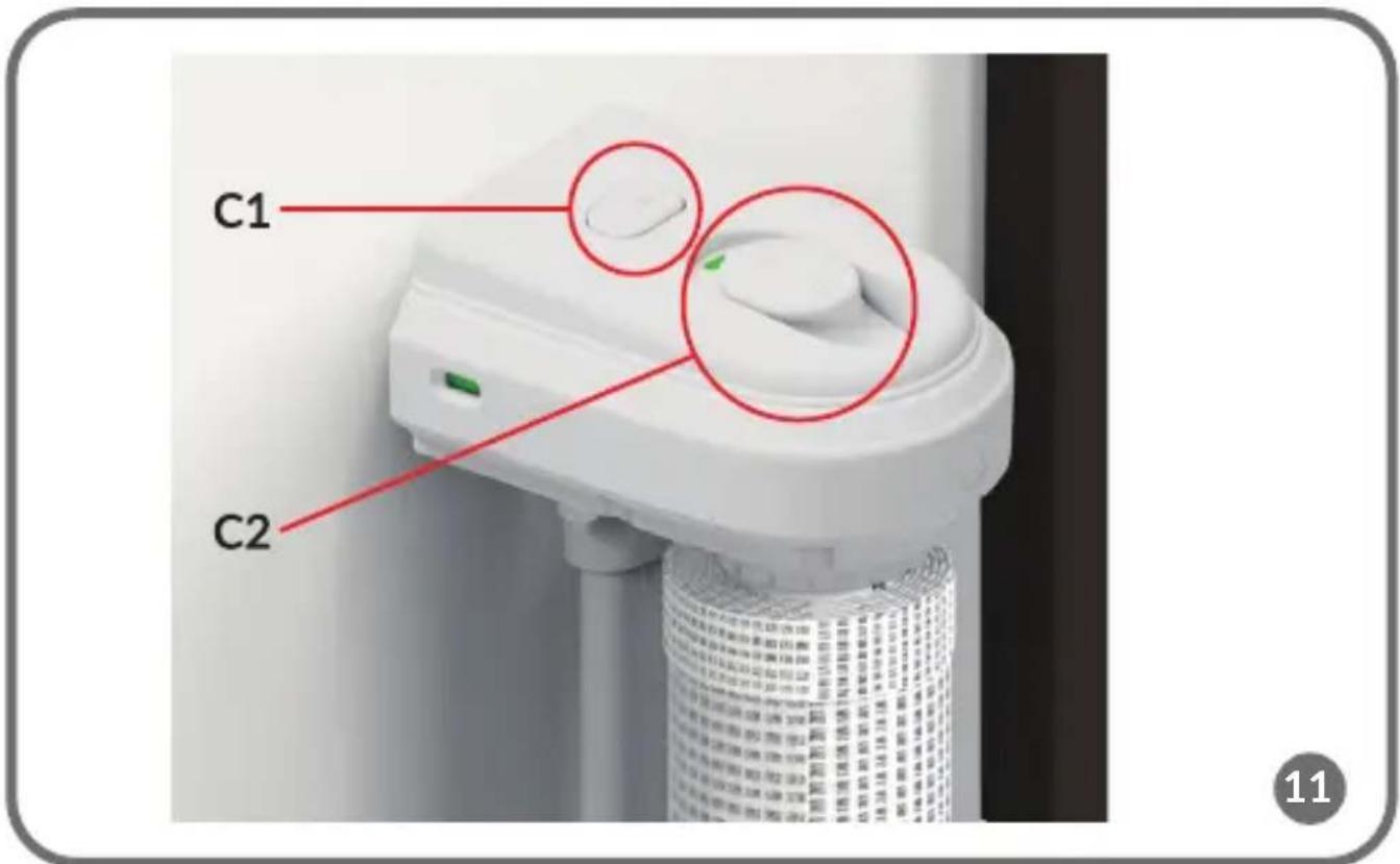
natural_image
Close-up of a wall-mounted fixture with a vertical cylindrical component and an upward arrow, mounted on a wooden floor (no text or symbols visible)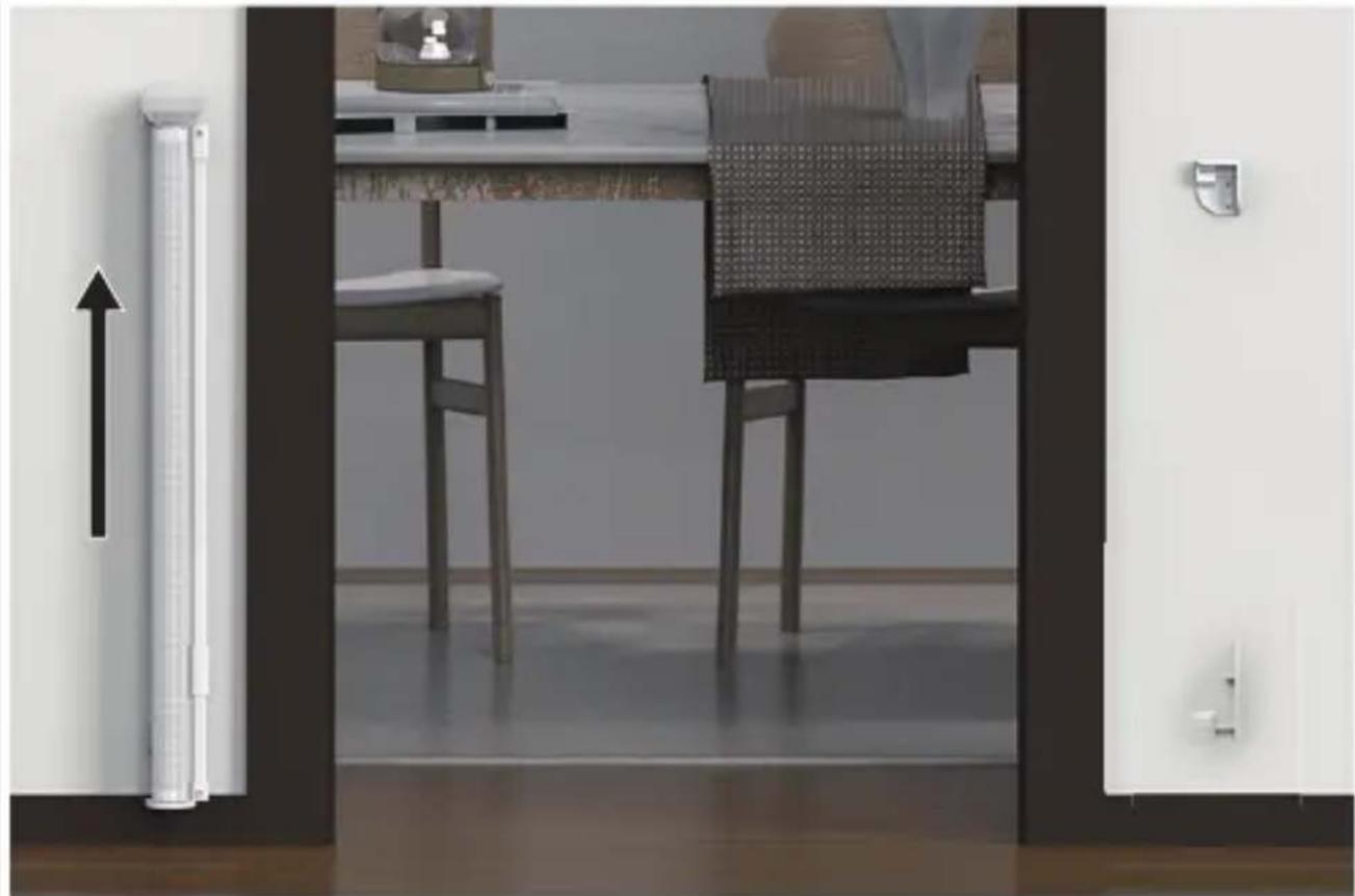
natural_image
Interior view of a modern kitchen or dining area with a table, chairs, and door (no visible text or symbols)Dear Customer!
In case of any questions or comments on the purchased product, please contact us:
help@lionelo.com
Producer:
BrandLine Group Sp. z o. o.
The product has been tested and meets all the requirements of EN 1930:2011.
WARNINGS IMPORTANT! READ AND FOLLOW THE INSTRUCTIONS AND KEEP FOR FUTURE REFERENCE.
Please read the entire instruction manual carefully before installing the product.
- WARNING - Incorrect installation can be dangerous.
- WARNING – Do not use the safety barrier if any components are damaged or missing.
- WARNING - The safety barrier must not be fitted across windows.
- This safety gate is intended for domestic use only.
- This safety gate is intended for use by children up to 24 months of age.
- If the safety gate is used at the bottom of a staircase, it is recommended that it is placed in front of the lowest step.
-
If the safety gate is used at the top of the stairs, it is recommended that it is not placed below the top level.
-
The safety gate should be inspected regularly to ensure that it meets its requirements, adequately protecting the space concerned, and to check its condition and compliance with the recommendations in this instruction manual.
- Any additional parts and replacements should only come from the manufacturer or distributor of the product.
- Make sure the gate is closed properly before use.
- Install only to a flat, stable surface using screws/screws and wall plugs.
- There is a risk that older children may try to climb the gate.
- If a child is able to climb onto the gate, discontinue use.
- The gate has a manual locking system.
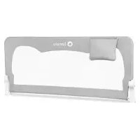
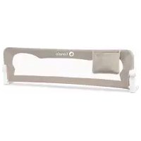
- This safety gate can be installed in doorways and at the bottom and top of stairs between 70 cm and 140 cm wide.
- The gate should not be installed on stairs. The gate can only be installed at the bottom or top of stairs and in doors.
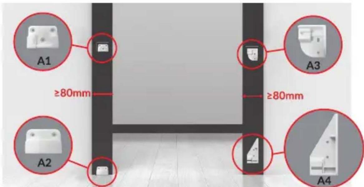
PARTS LIST (FIG. A)
A1.-A4. Wall mounting brackets
A5.-A6. Brackets for extending part
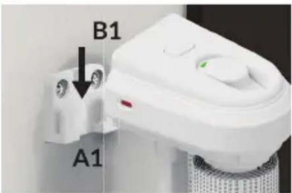
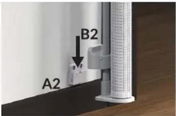
B1. Gate upper mounting bracket
B2. Gate lower mounting bracket
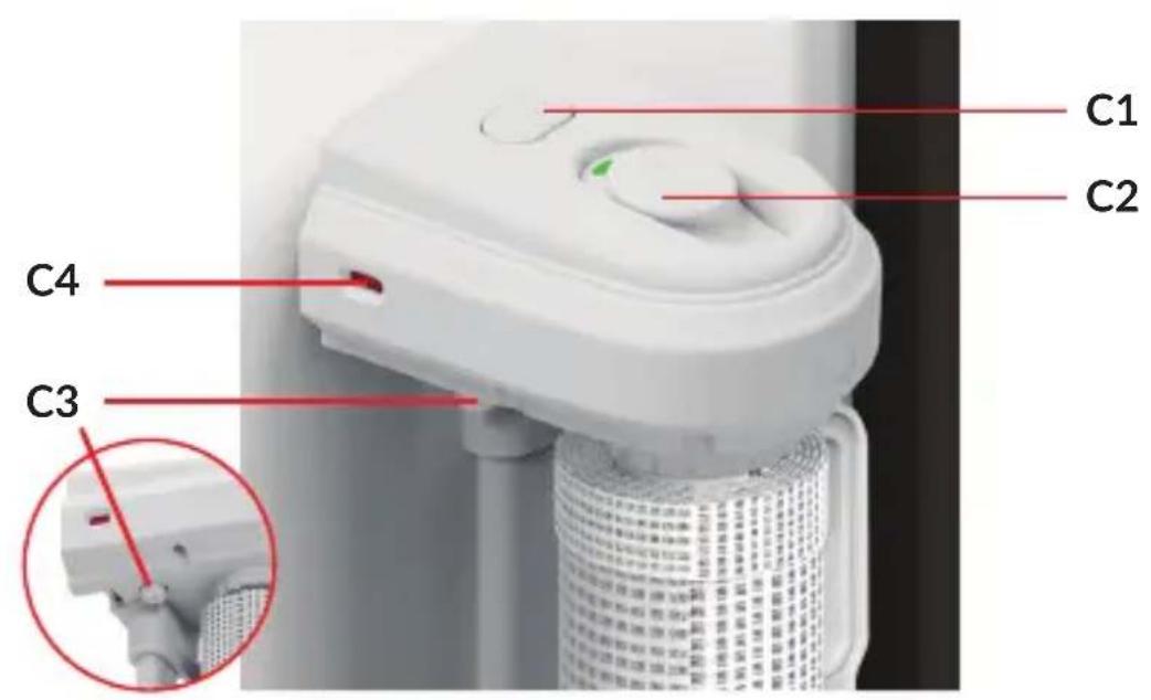
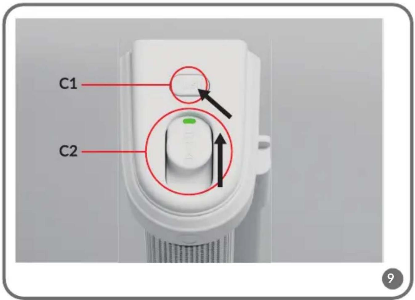
C1. Lock button
C2. Unlock button and lock indicator
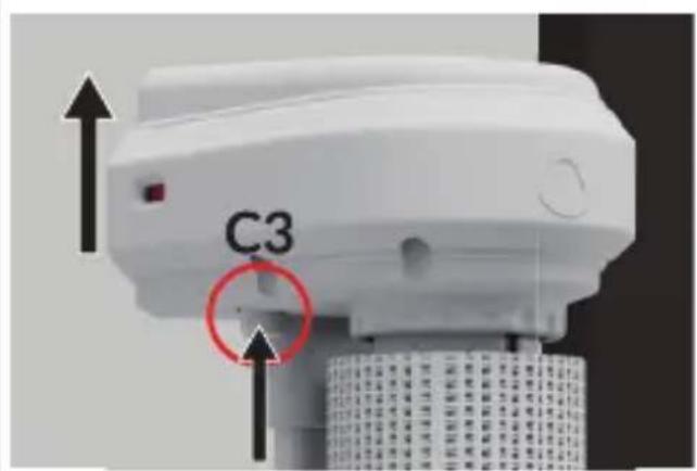
C3. Removal button
C4. Indicator of correct installation
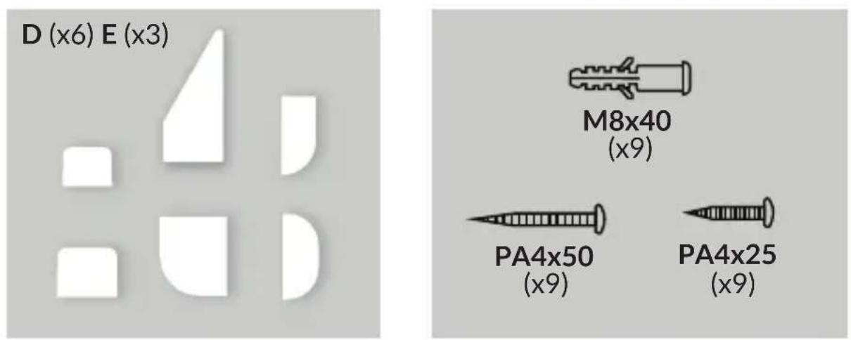
D. Adhesive tapes (3 sets)
E. Screws and wall plugs - PA4x50 screws (x9), PA4x25 screws (x9), wall plugs (x9) - 3 sets
IMPORTANT INFORMATION
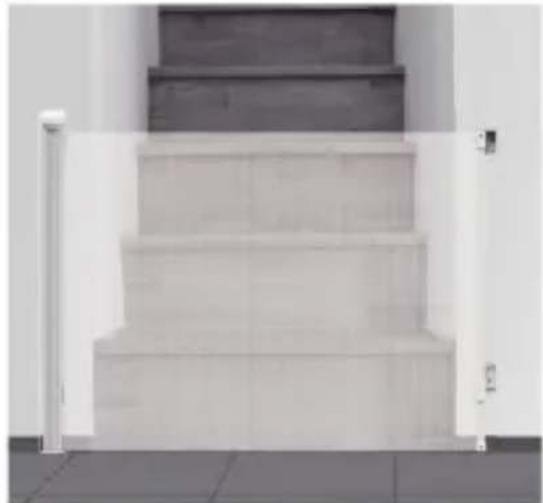
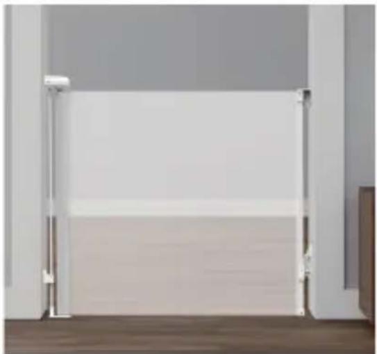
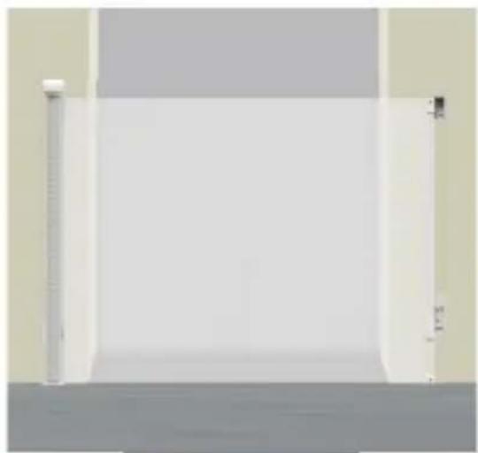
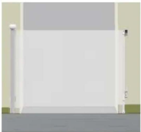
The gate can be installed at the bottom or top of the staircase (1), in a door with frame (2), without frame (3), or in a door with skirting board (4), (fig. B).
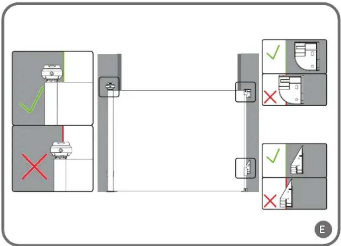
During installation, care should be taken to ensure that the wall mounting brackets are correctly positioned. Each bracket should be positioned fully on the wall (fig. E), with their edges parallel to the edge of the door.
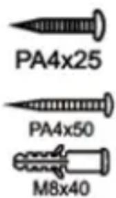
Screws should be used when installing to wooden surfaces.
Long screws and wall plugs should be used when installing to hard surfaces with a skirting board, such as concrete walls or wall tiles.
Short screws and wall plugs should be used when installing to hard surfaces without a skirting board, such as concrete walls or wall tiles.
INSTALLATION
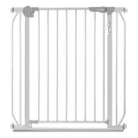
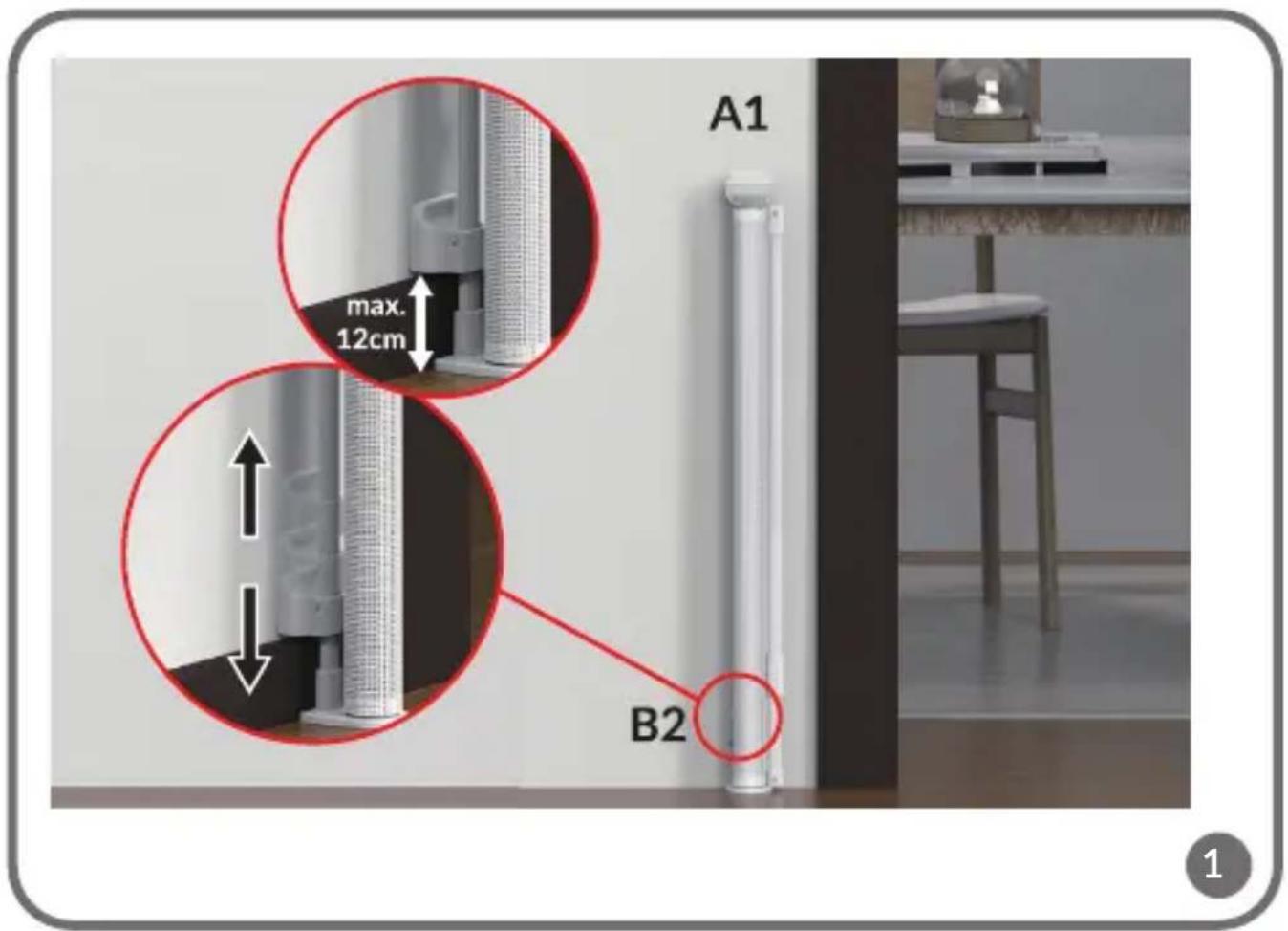
- Place the gate in the chosen installation location. The lower edge of the gate must be adjacent to the floor. Adjust the height of the bottom bracket (B2, fig. 1) to the height of the skirting board (max. 12 cm above floor level) and tighten the screw so that the bracket remains fixed. Then insert the brackets marked A1 and A2 (fig. C) into parts B1 and B2 (fig. A).
Note! If there is no skirting board, also do not install the lower support (B2) higher than 12 cm above floor level (fig. 1).
-
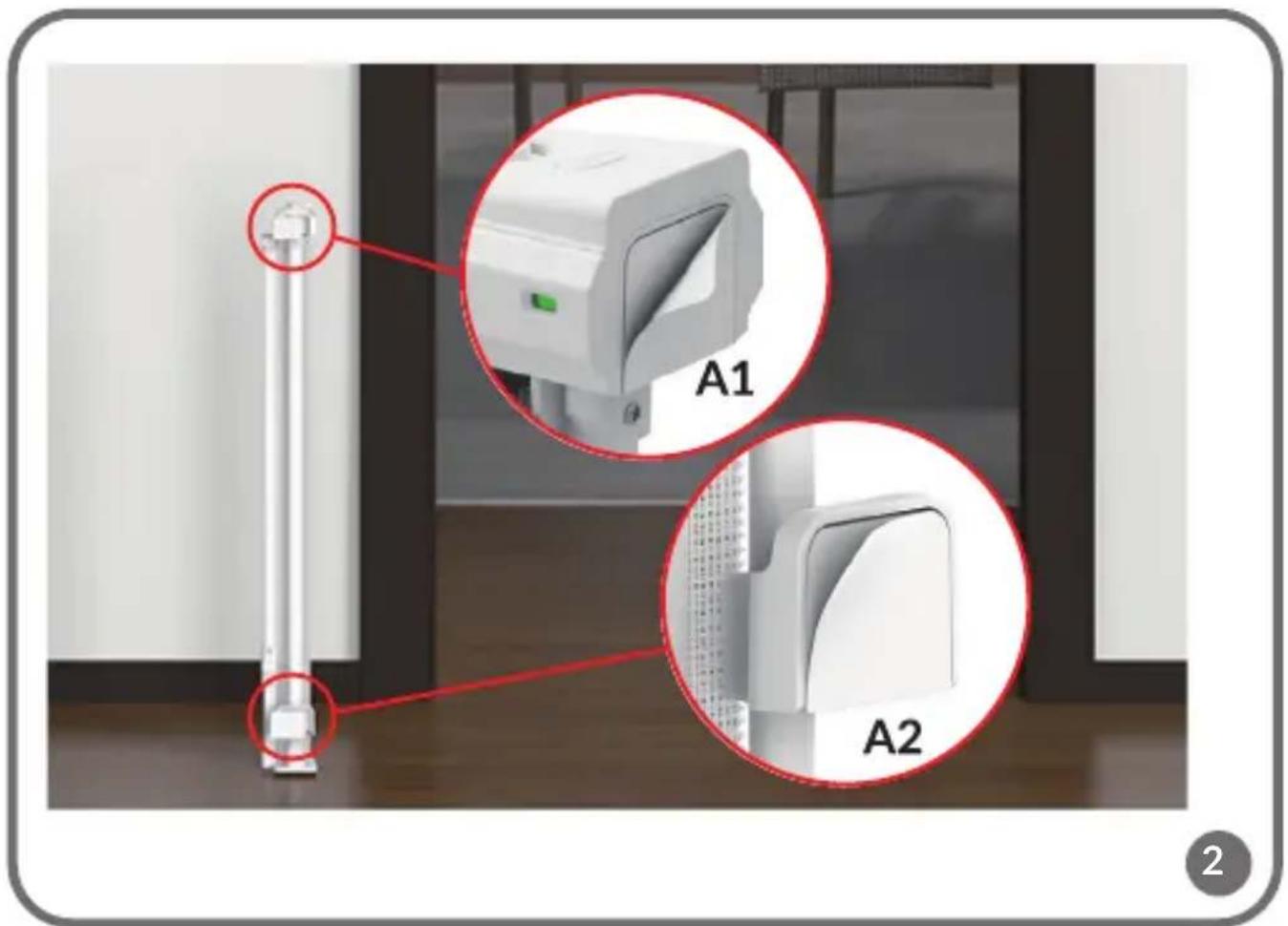
Place the adhesive tape on the brackets marked A1 and A2 (fig. 2). Fix the gate to the wall.
-
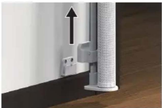
Take the gate out from the brackets. To take the gate out of the brackets, press the button marked C3 (fig. 3) and lift it gently upwards.
-
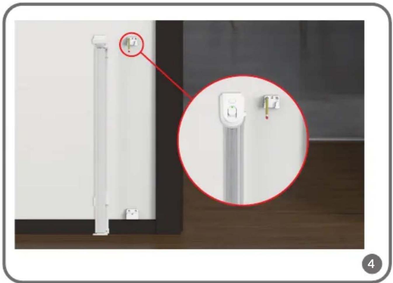
Mark on the wall the heights where the A1 and A2 bracket mounting screws will be located (fig. 4). You can also use the punches provided on the package.
-
Remove the brackets from the wall. Drill the holes at the marked positions. Use screws to reinstall the brackets (fig. 5).
-
Slide the gate into the corresponding brackets (fig. 6). The correct installation indicator (C4, fig. A) on the left side of the head will turn green, indicating correct installation (fig. 6).
-
Unroll the railing to the desired width. Make sure the material is even and free of creases.
-
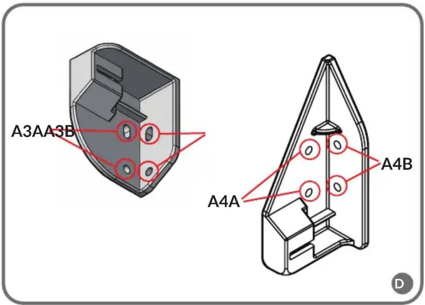
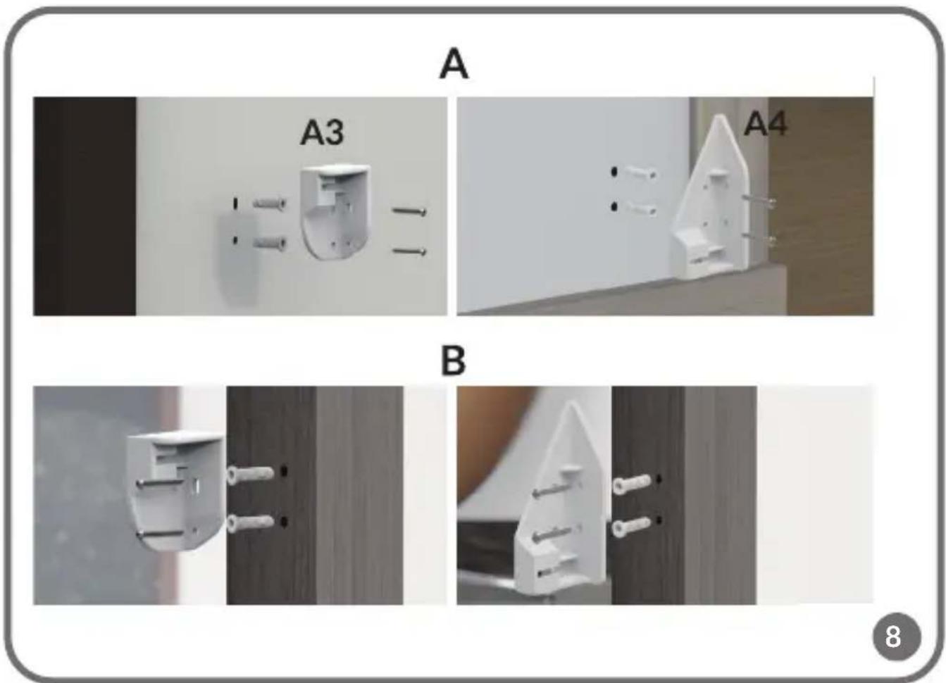
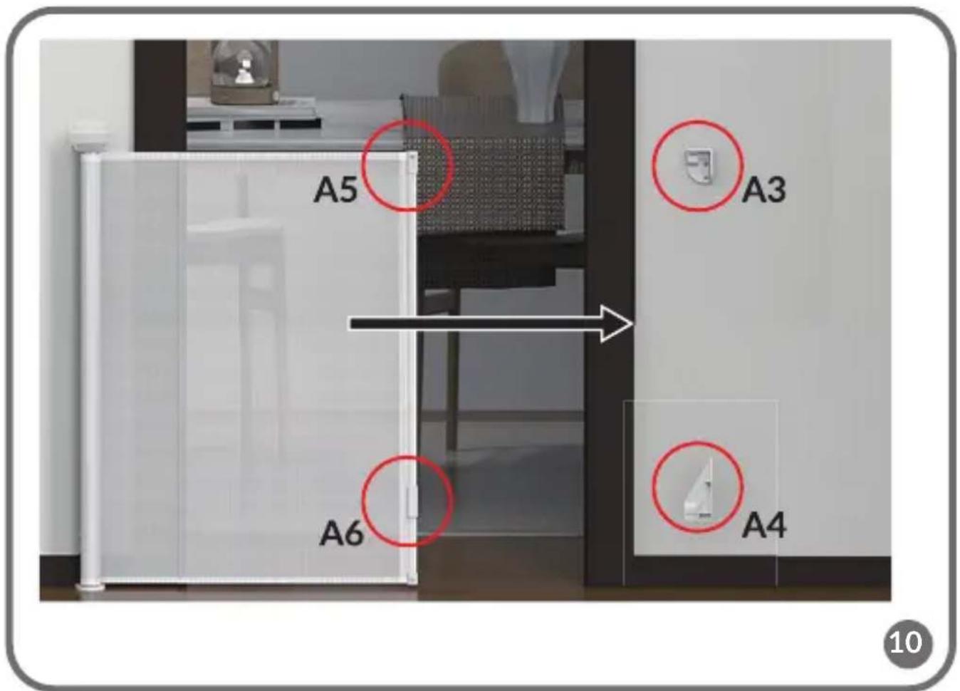
Place the A3 and A4 brackets in the desired position (fig. 7). Make sure the brackets are in the correct position (fig. C, D). Mark on the wall the heights where the screws of the A3 and A4 brackets will be located. You can also use the punches provided on the package.
-
Drill the holes at the marked positions. Use the screws to install the brackets (fig. 8).
Note! When the gate is fixed on the wall, outside the door frame (A, fig. 8), the brackets A3 and A4 (fig. C) must be installed in the holes A3A and A4A
(fig. D). When the gate is fixed on the door frame (B, fig. 8), the brackets A3 and A4 (fig. C) must be installed in the holes A3B and A4B (fig. D).
USE
- To unlock the gate, press button C1 while moving button C2 (fig. 9). While holding the C2 button, release the C1 button and then release the C2 button. The lock indicator next to button C2 will turn red.
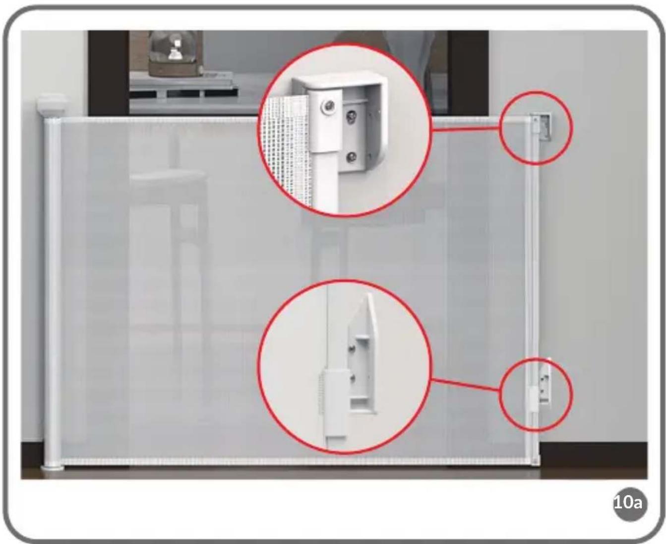
- Unroll the gate and insert the handles of the extension part (A5 and A6, fig. A) into the brackets A3 and A4 on the wall (fig. 10). Make sure they are inserted correctly and that the gate is stable and securely closed (fig. 10a).
- Lock the gate by pressing button C1 (fig. A). Make sure that the gate is correctly locked. The lock indicator next to button C2 will turn green (fig. 11).
REMOVAL
To remove the gate from the brackets, press the button marked C3 and lift it gently upwards (fig. 12).
CLEANING AND MAINTENANCE
- To clean the gate, wipe it with a damp cloth or sponge soaked in warm water with a mild detergent. Do not use abrasives, ammonia or alcohol-based cleaners or bleach for cleaning.
• Any additional parts and replacements should only come from the manufacturer or distributor of the product.
Photos are for illustrative purposes only, the actual appearance of the products may differ from those shown in the photos. Dum perfecut imilica
PL
Drogi Kliencie!
BrandLine Group Sp. z o.o.
BrandLine Group Sp. z o.o.