
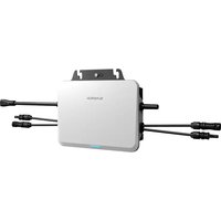
SH25T - Power inverter Sungrow - Free user manual and instructions
Find the device manual for free SH25T Sungrow in PDF.

| Product Type | Hybrid Electric Inverter |
| Brand | Sungrow |
| Model | SH25T |
| Nominal AC Power | 25 kW |
| Max PV Input Voltage | 1000 V |
| MPPT Range | 200 - 850 V |
| Number of MPPT Trackers | 2 |
| AC Output Voltage | 400 V Three-phase |
| Output Frequency | 50 / 60 Hz |
| Maximum Efficiency | 98 % |
| Protection Rating | IP65 |
| Operating Temperature | -25 °C to +60 °C |
| Dimensions (W x H x D) | 600 x 800 x 300 mm |
| Weight | 60 kg |
| Cooling | Forced Convection |
| Display | LCD |
| Communication | WiNet-S2 (WLAN) |
| Compatible Battery | Yes (High Voltage) |
| Warranty | 5 years |
| Standards | CE, TÜV, RCM |
| Maintenance | Regular cleaning of heat sinks |
Frequently Asked Questions - SH25T Sungrow
User questions about SH25T Sungrow
0 question about this device. Answer the ones you know or ask your own.
Ask a new question about this device
Download the instructions for your Power inverter in PDF format for free! Find your manual SH25T - Sungrow and take your electronic device back in hand. On this page are published all the documents necessary for the use of your device. SH25T by Sungrow.
USER MANUAL SH25T Sungrow
Quick Installation Guide
3-Phase Hybrid Inverter
natural_image
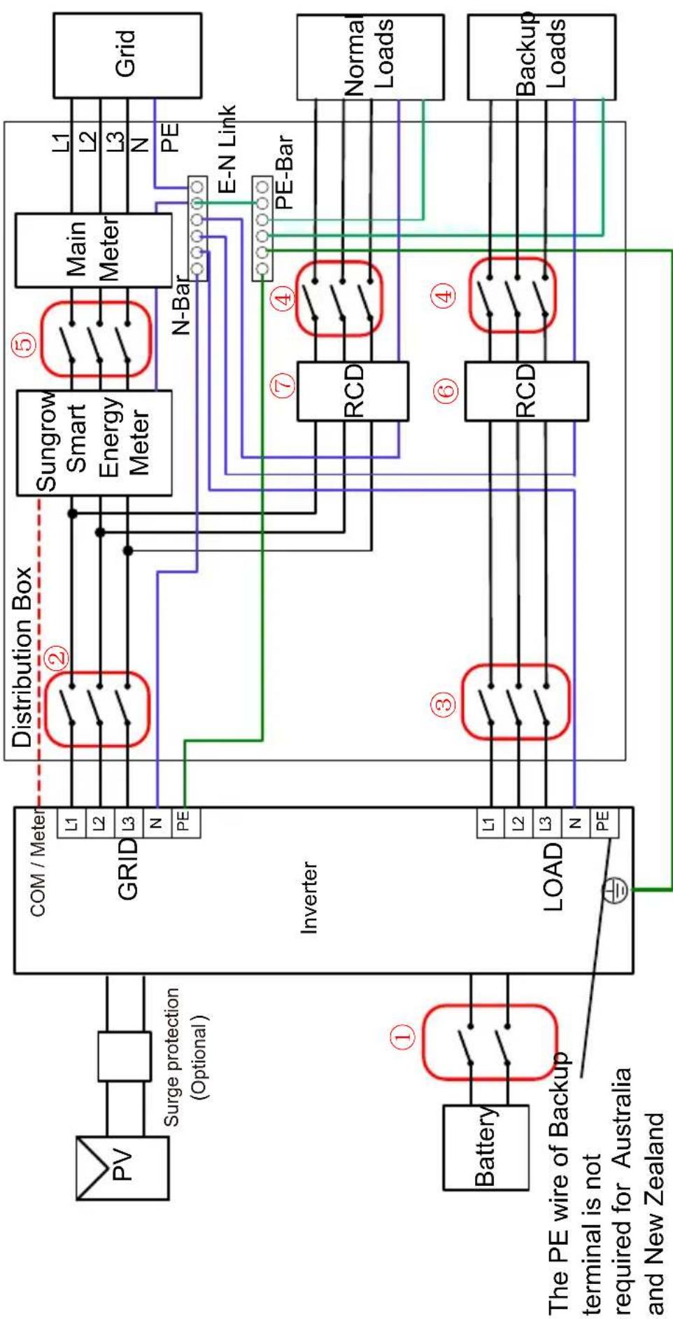
White Sungrow industrial control unit with black connectors and a digital display (no readable text or symbols beyond branding)Backup Wiring Diagram (For AU / NZ) Loads Connected to the Grid :
| Model | 1 | 2 | 3 | 4 | 5 | 6 | 7 | |
| SH5/6T | 63A/800V DC breaker * | 25-63A/400V TypeB AC breaker** | Depends on loads | Depends on loads | Depends on household loads and inverter capacity | 30mA RCD (Comply with local regulation) | ||
| SH8/10/12T | 32-63A/400V TypeB AC breaker** | |||||||
| SH15T | 63A/400V TypeB AC breaker** | |||||||
| SH20/25T | 63A/400V TypeB AC breaker** | |||||||
| Note: * If the battery is integrated with a readily accessible internal DC breaker, no additional DC breaker is required. | ||||||||
| Note: **Type B is recommended, and Type C is Compatible. Select an MCB with an appropriate rated current based on the actual requirements, including the overall wiring scheme, the number of loads, and the inverter's load-carrying capacity. | ||||||||
| Note: The values in the table are recommended values and can be set to other values according to actual conditions. | ||||||||
flowchart
graph TD
    A["PV"] --> B["Surge protection (Optional)"]
    B --> C["GRID"]
    C --> D["Distribution Box"]
    D --> E["Sungrow Smart Energy Meter"]
    E --> F["Main Meter"]
    F --> G["Grid"]
    H["Battery"] --> I["The PE wire of Backup terminal is not required for Australia and New Zealand"]
    I --> J["LOAD"]
    J --> K["RCD"]
    K --> L["PE-Bar"]
    L --> M["Normal Loads"]
    L --> N["Backup Loads"]
    O["PE"] --> P["N-Bar"]
    Q["PE"] --> R["E-N Link"]
    S["PE"] --> T["PE-Bar"]
    U["L1"] --> V["Distribution Box"]
    W["L2"] --> V
    X["L3"] --> V
    Y["N"] --> V
    Z["PE"] --> V
    style A fill:#f9f,stroke:#333
    style H fill:#f9f,stroke:#333
    style O fill:#f9f,stroke:#333
    style U fill:#f9f,stroke:#333
    style V fill:#ccf,stroke:#333
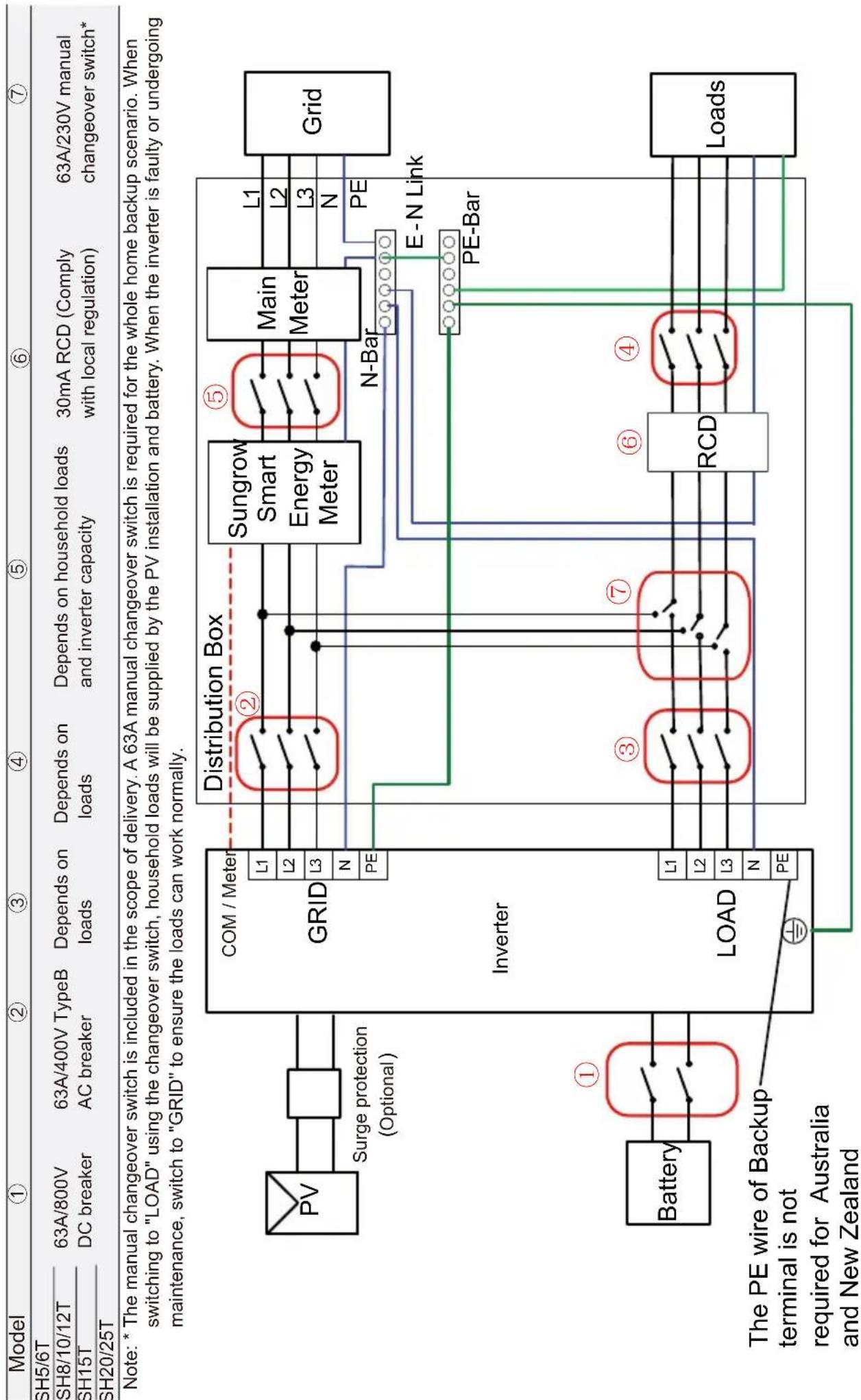
Whole Home Backup Wiring Diagram (For AU / NZ) Loads Connected to the Inverter :
flowchart
graph TD
    A["Model"] --> B["①"]
    B --> C["SH5/6T"]
    B --> D["SH8/10/12T"]
    B --> E["SH15T"]
    B --> F["SH20/25T"]
    C --> G["63A/800V DC breaker"]
    D --> H["63A/400V TypeB AC breaker"]
    E --> I["Depends on loads"]
    F --> J["Depends on loads and inverter capacity"]
    G --> K["Distribution Box"]
    H --> K
    I --> K
    J --> K
    K --> L["Sungrow Smart Energy Meter"]
    K --> M["Main Meter"]
    L --> N["L1"]
    L --> O["L2"]
    L --> P["L3"]
    M --> Q["L1"]
    M --> R["L2"]
    M --> S["L3"]
    N --> T["N-Bar"]
    O --> T
    P --> T
    Q --> U["E-N Link"]
    R --> V["PE-Bar"]
    S --> V
    T --> W["Load"]
    U --> W
    V --> W
    W --> X["PE-Bar"]
    Y["Battery"] --> Z["①"]
    Z --> AA["Distribution Box"]
    AB["LOAD"] --> AC["Distribution Box"]
    AD["The PE wire of Backup terminal is not required for Australia and New Zealand"] --> AE["Ground"]
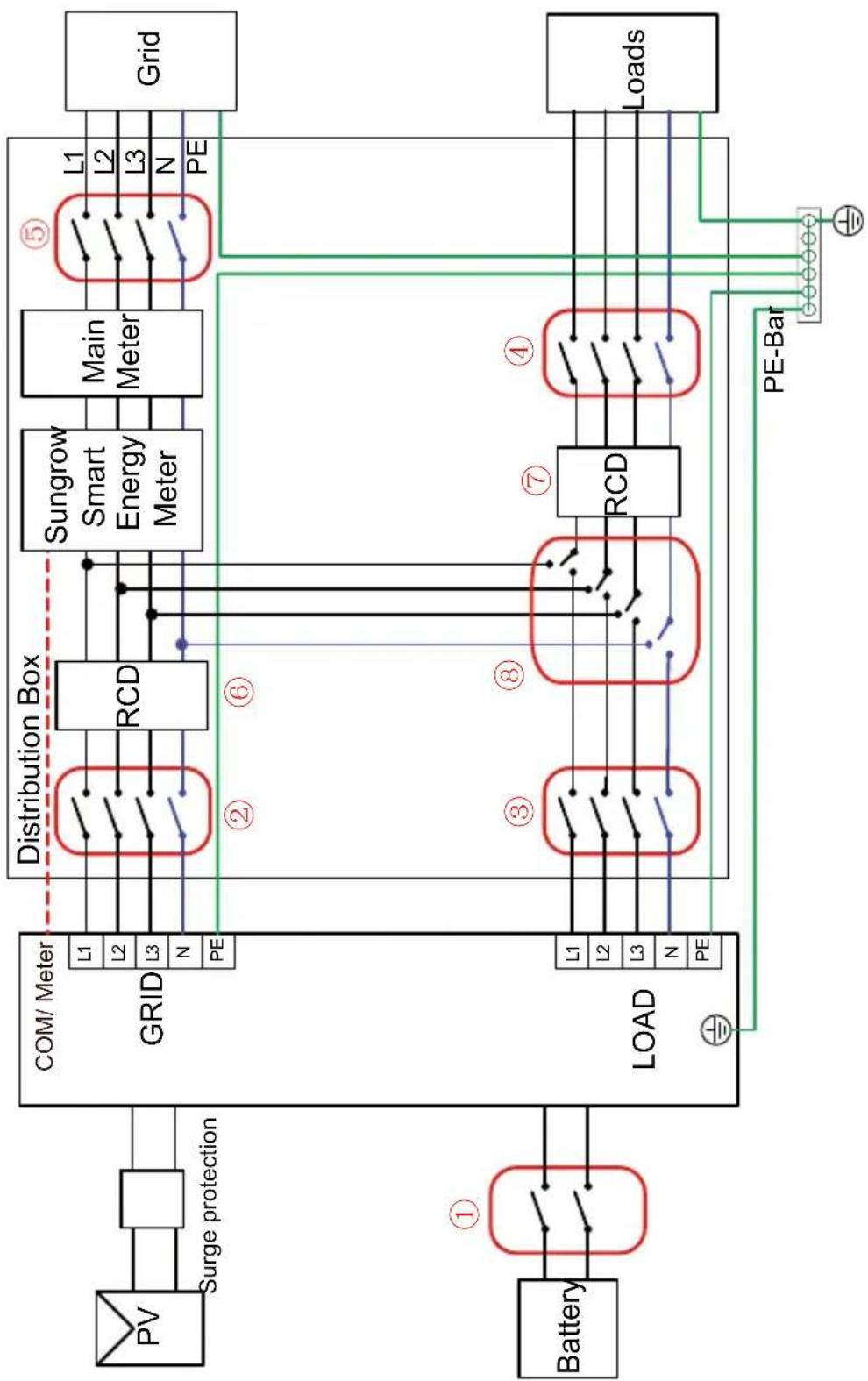
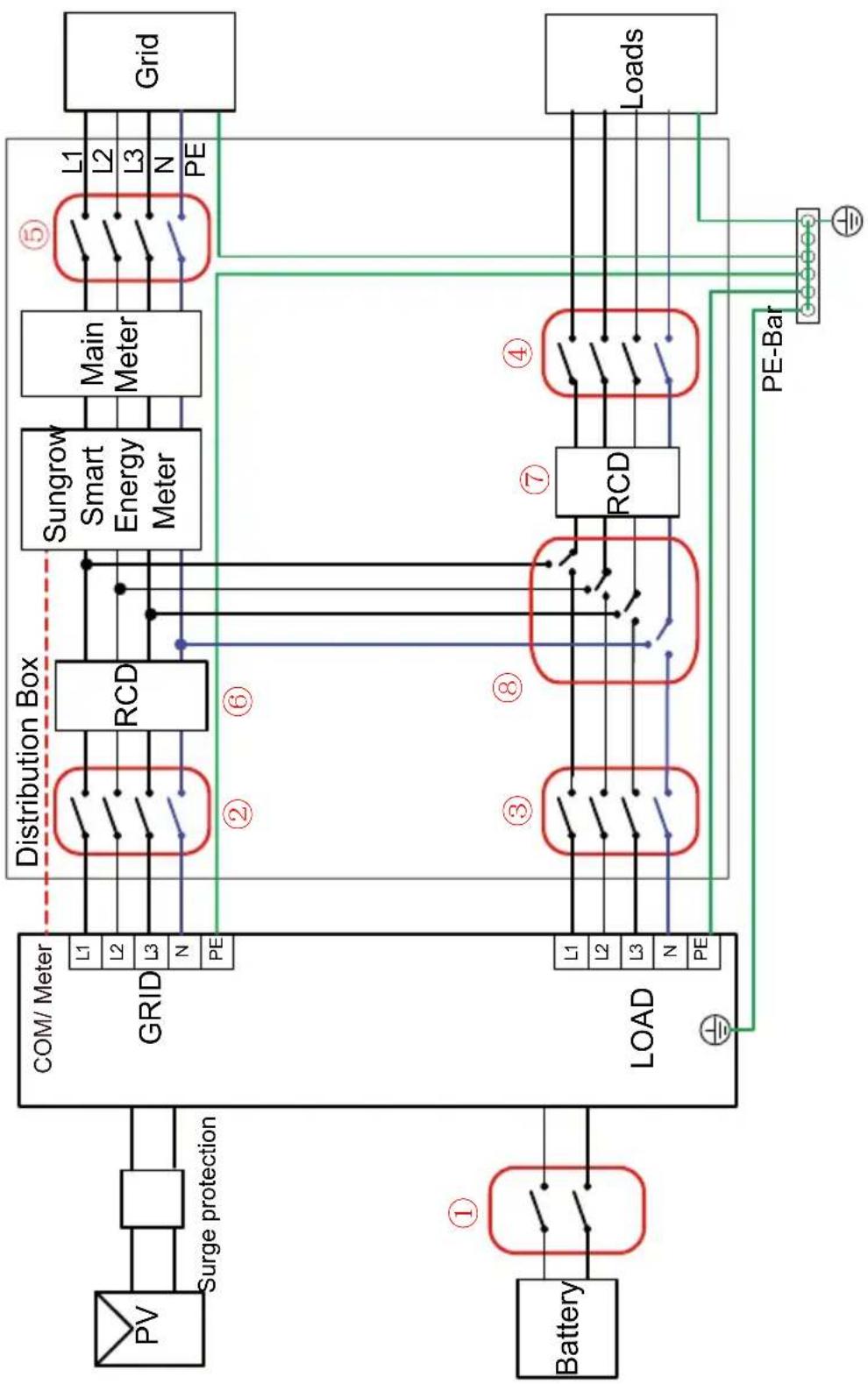
Backup Wiring Diagram (For Other Countries) Loads Connected to the Grid:
| ①Model | ② | ③ | ④ | ⑤ | ⑥ | ⑦ | ⑧ | |
| 5/6T3/10/12T5T20/25T | 63A/800V DC breaker * | 25-63A/400V** TypeB AC breaker32-63A/400V** TypeB AC breaker63A/400V** TypeB AC breaker63A/400V** TypeB AC breaker | Depends on loads | Depends on loads | Depends on household loads and inverter capacity | 30mA RCD (Comply with local regulation) | 300mA RCD (Comply with local regulation) | |
| Note: * If the battery is integrated with a readily accessible internal DC breaker, no additional DC breaker is required. Note: **Select an MCB with an appropriate rated current based on the actual requirements, including the overall wiring scheme, the number of loads, and the inverter's load-carrying capacity. Note: The values in the table are recommended values and can be set to other values according to actual conditions. Note: The installer is responsible to know what is additionally required in each country. | ||||||||
| PV | Surge protection | Distribution Box | ||||||
| GRID | L1 | RCD | Sungrow Smart Energy Meter | Main Meter | ⑤ | Grid | ||
| L2 | L1 | L2 | ||||||
| L3 | L2 | L3 | ||||||
| N | N | PE | ||||||
| PE | ||||||||
| Battery | ① | Inverter | ② | ⑧ | ⑥ | ④ | Norma Loads | |
| L1 | ||||||||
| L2 | ||||||||
| L3 | ||||||||
| LOAD | ③ | ⑦ | ④ | Backup Loads | ||||
| L1 | ||||||||
| L2 | ||||||||
| L3 | ||||||||
| N | ||||||||
| PE | ||||||||
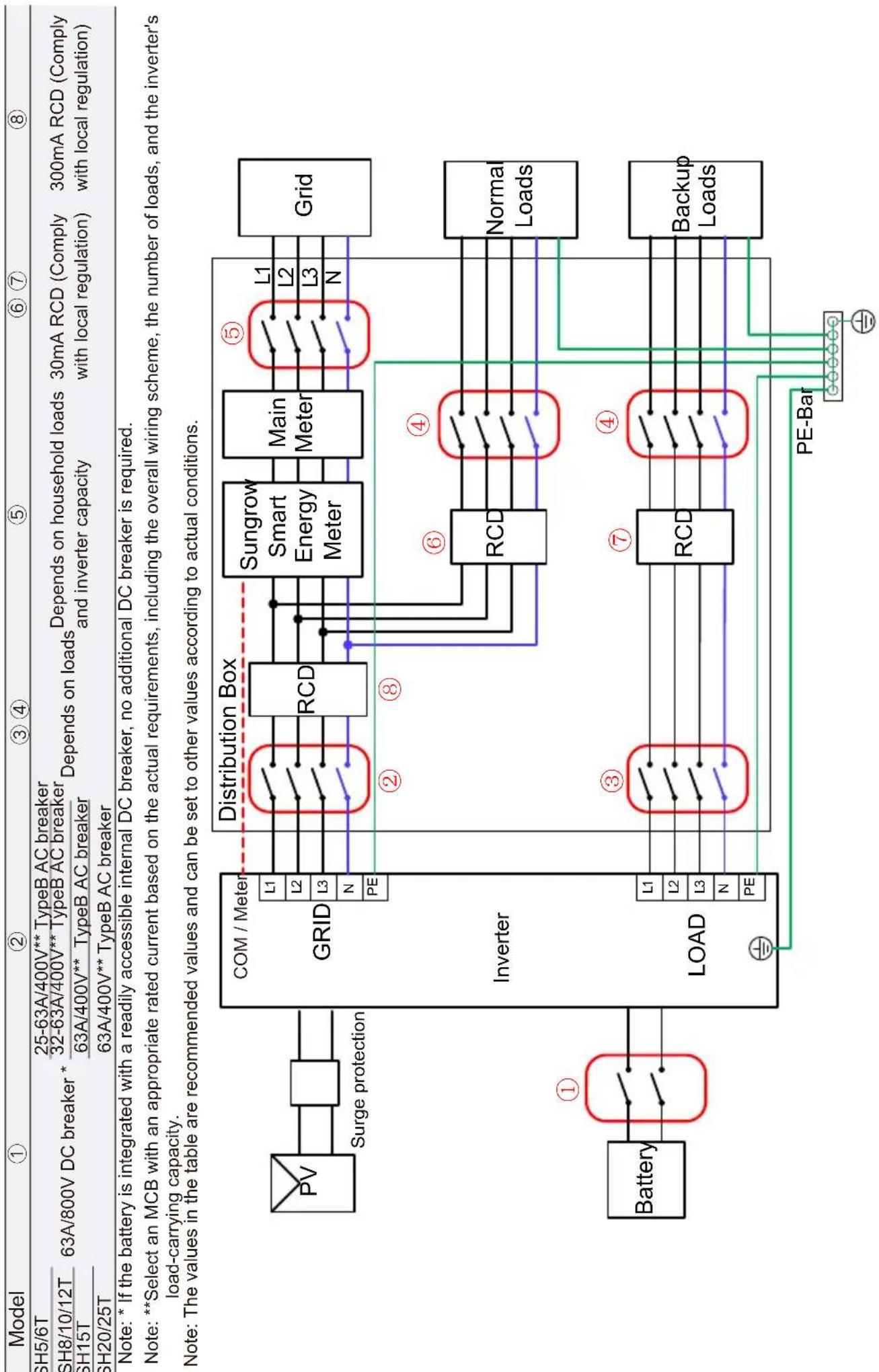
Whole Home Backup Wiring Diagram (For Other Countries) Loads Connected to the Inverter:
| Model | 1 | 2 | 34 | 5 | 6 | 7 | 8 |
| SH5/6T | |||||||
| SH8/10/12T | 63A/800VDC breaker | 63A/400V TypeBAC breaker | Depends on loads | Depends on household loads and inverter capacity | 300mA RCD (Comply with local regulation) | 30mA RCD (Comply with local regulation) | ≥63A/230V manual changeover switch* |
| SH15T | |||||||
| SH20/25T |
Note: *The manual changeover switch should be prepared by users separately. For the whole home backup scenario, it is recommended to use at least a 63A manual changeover switch, with 80A or 100A preferred. When switching to "LOAD" using the changeover switch, household loads will be supplied by the PV installation and battery. When the inverter is faulty or undergoing maintenance, switch to "GRID" to ensure the loads can work normally. Note: The installer is responsible to know what is additionally required in each country.
flowchart
graph TD
    PV["PV"] --> SurgeProtection["Surge protection"]
    SurgeProtection --> Grid1["GRID"]
    Grid1 --> DistributionBox["Distribution Box"]
    DistributionBox --> RCD1["RCD"]
    DistributionBox --> RCD2["RCD"]
    RCD1 --> SunGrowthSmartMeter["Sungrow Smart Energy Meter"]
    RCD2 --> SunGrowthSmartMeter
    SunGrowthSmartMeter --> MainMeter["Main Meter"]
    MainMeter --> Grid2["Grid"]
    Battery["Battery"] --> Load1["LOAD"]
    Load1 --> L1["L1"]
    Load1 --> L2["L2"]
    Load1 --> L3["L3"]
    Load1 --> N["N"]
    Load1 --> PE["PE"]
    PE --> DistributionBox
    Li1 --> DistributionBox
    Li2 --> DistributionBox
    Li3 --> DistributionBox
    N --> DistributionBox
    PE --> DistributionBox
    Li1 --> RCD3["RCD"]
    Li2 --> RCD3
    Li3 --> RCD3
    N --> RCD3
    PE --> RCD3
    RCD3 --> SunGrowthSmartMeter
    SunGrowthSmartMeter --> Grid2
    SunGrowthSmartMeter --> Grid4["Grid"]
    Grid4 --> Load2["Loads"]
    Load2 --> PE-Bar["PE-Bar"]
    PE-Bar --> Grid5["Grid"]
    Grid5 --> Grid6["Grid"]
Backup Wiring Diagram (For TT system) Loads Connected to the Grid :
flowchart
graph TD
    A["Battery"] -->|①| B["Com / Meter"]
    B --> C["Distribution Box"]
    C --> D["RCD"]
    D --> E["Sungrow Smart Energy Meter"]
    E --> F["Main Meter"]
    F --> G["Grid"]
    G --> H["Normal Loads"]
    H --> I["Backup Loads"]
    I --> J["PE-Bar"]
    J --> K["Load"]
    K --> L["Inverter"]
    L --> M["GRID"]
    M --> N["Surge protection"]
    N --> O["PV"]
    O --> P["63A/800V DC breaker *"]
    style A fill:#f9f,stroke:#333
    style B fill:#ccf,stroke:#333
    style C fill:#cfc,stroke:#333
    style D fill:#fcc,stroke:#333
    style E fill:#cff,stroke:#333
    style F fill:#ffc,stroke:#333
    style G fill:#fcf,stroke:#333
    style H fill:#cff,stroke:#333
    style I fill:#ffc,stroke:#333
    style J fill:#cfc,stroke:#333
    style K fill:#fcc,stroke:#333
    style L fill:#cfc,stroke:#333
    style M fill:#cfc,stroke:#333
    style N fill:#cfc,stroke:#333
    style O fill:#fcc,stroke:#333
    style P fill:#cfc,stroke:#333
    style Q fill:#fcc,stroke:#333
    style R fill:#cfc,stroke:#333
    style S fill:#cfc,stroke:#333
    style T fill:#cfc,stroke:#333
    style U fill:#cfc,stroke:#333
    style V fill:#cfc,stroke:#333
    style W fill:#cfc,stroke:#333
    style X fill:#cfc,stroke:#333
    style Y fill:#cfc,stroke:#333
    style Z fill:#cfc,stroke:#333
Whole Home Backup Wiring Diagram (For TT system) Loads Connected to the Inverter:
| Model | 1 | 2 | 3 | 4 | 5 | 6 | 7 | 8 |
| SH5/6T | ||||||||
| SH8/10/12T | 63A/800VDC breaker | 63A/400V TypeBAC breaker | Depends on loads | Depends on household loads and inverter capacity | 300mA RCD (Comply with local regulation) | 30mA RCD (Comply with local regulation) | ≥63A/230V manual changeover switch* | |
| SH15T | ||||||||
| SH20/25T |
Note: * The manual changeover switch should be prepared by users separately. For the whole home backup scenario, it is recommended to use at least a 63A manual changeover switch, with 80A or 100A preferred. When switching to "LOAD" using the changeover switch, household loads will be supplied by the PV installation and battery. When the inverter is faulty or undergoing maintenance, switch to "GRID" to ensure the loads can work normally.
flowchart
graph TD
    PV["PV"] --> SurgeProtection["Surge protection"]
    SurgeProtection --> GridGRID["Grid"]
    Battery["Battery"] --> LoadLOAD["Load"]
    LoadLOAD --> DistributionBox["Distribution Box"]
    DistributionBox --> RCD1["RCD"]
    DistributionBox --> RCD2["RCD"]
    RCD1 --> SunGrowthSmartMeter["Sungrow Smart Energy Meter"]
    RCD2 --> SunGrowthSmartMeter
    SunGrowthSmartMeter --> MainMeter["Main Meter"]
    MainMeter --> GridGrid["Grid"]
    LoadLoad["Loads"] --> PE-Bars["PE-Bar"]
    PE-Bars --> GridGrid
    GridGrid -->|①| Battery
    GridGrid -->|②| DistributionBox
    GridGrid -->|③| LoadLOAD
    GridGrid -->|④| RCD3["RCD"]
    GridGrid -->|⑤| MainMeter
    GridGrid -->|⑥| RCD4["RCD"]
    GridGrid -->|⑦| SunGrowthSmartMeter
    SUNGrowthSmartMeter -->|L1-L3| GridGrid
    SUNGrowthSmartMeter -->|N-PE| GridGrid
    GridGrid -->|L1-L3| GridGrid
    GridGrid -->|PE-Bars| LoadLoad
Scope of Delivery / Lieferumfang / Contenuto della fornitura / Contenu de la livraison / Leveringsomvang / Zakres dostawy / Contenido suministrado / Âmbito de entrega / Leveransens innehåll
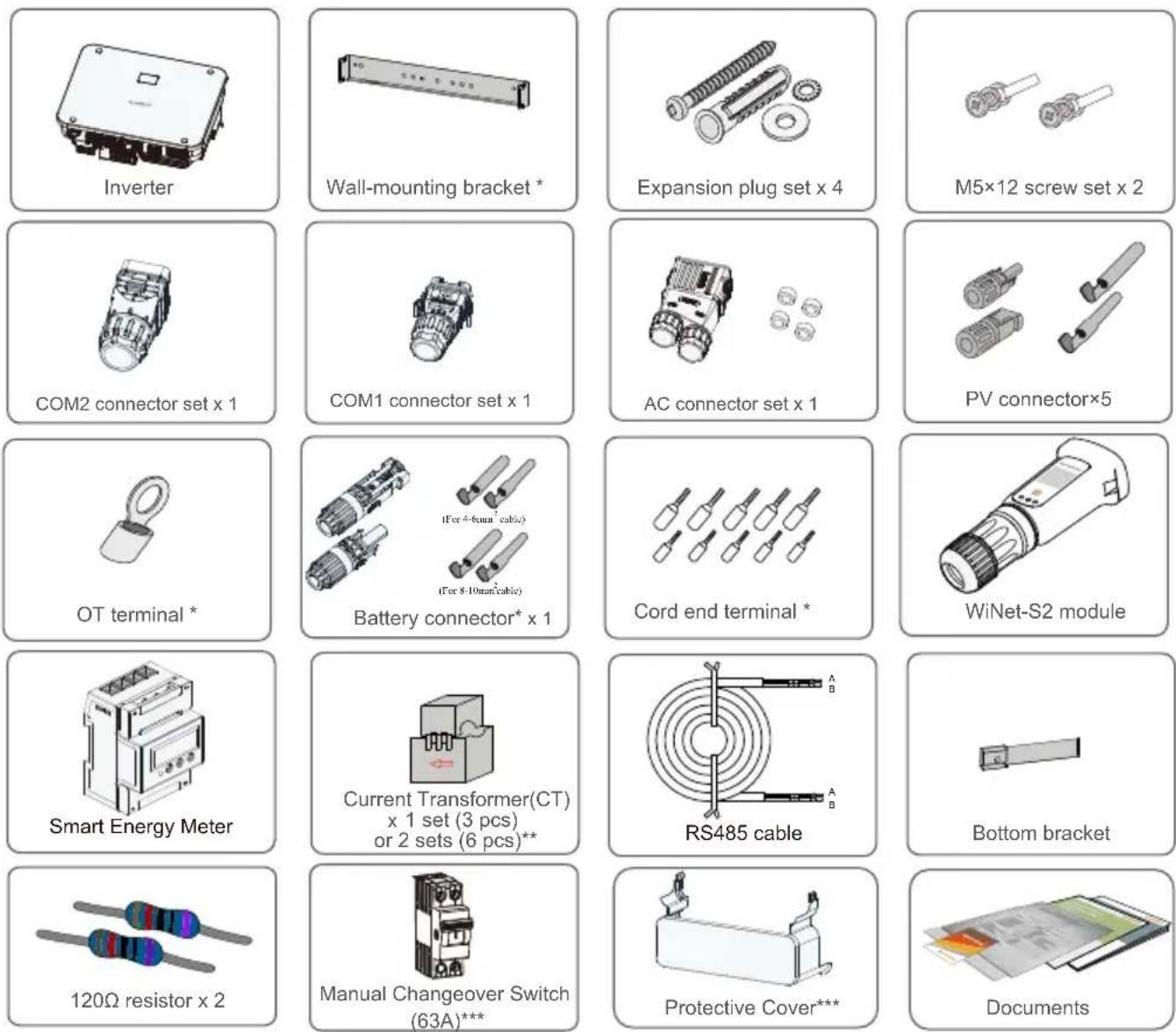
* The images shown here are for reference. The actual product and quantity are based on delivery.
**The Australia and New Zealand region is equipped with 6 x 100A/0.333V CT as standard, and the other areas are equipped with 3 x 100A/0.333V CT as standard.
*** These accessories are included in the scope of delivery only in Australia currently.

natural_image
Diagram showing a fire hazard symbol (X) on a fire inside a building, with no text or labels present.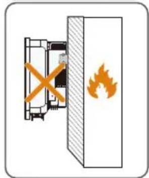
natural_image
Diagram showing a fire extinguisher inside a fire shield, with no text or symbols present.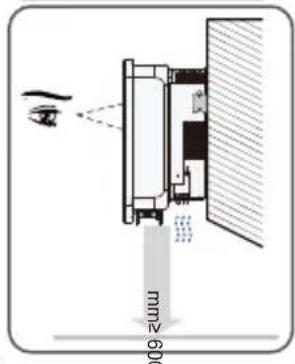
natural_image
Illustration of a cardboard box with a cross mark on the cover (no text or symbols)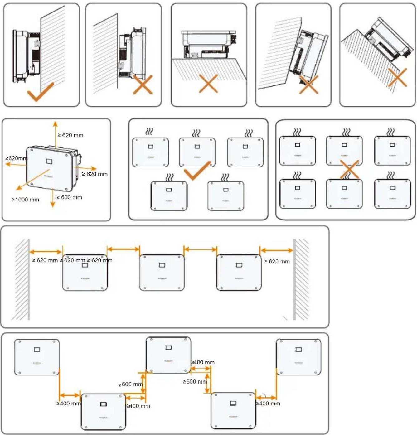
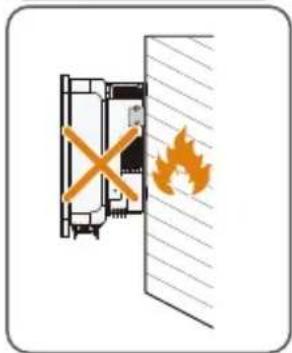
- For more information about mounting location, please contact SUNGROW.
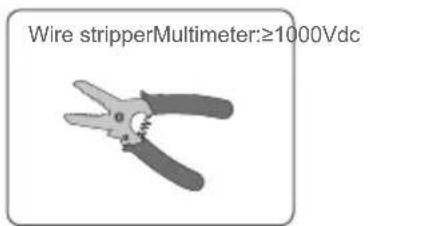
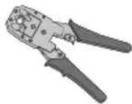
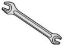
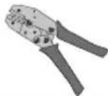
Installation tools / Werkzeug zur Installation / Strumenti di installazione/ Outils d'installation/ Montagegereedschap / Narzędzia montażowe / Herramientas de instalación / Ferramentas de instalação / Installationsverktyg
natural_image
Black pen icon labeled 'Marker' on white background (no other text or symbols)

natural_image
Illustration of a mechanical tool with a handle and lever (no text or symbols)
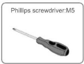

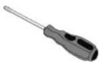
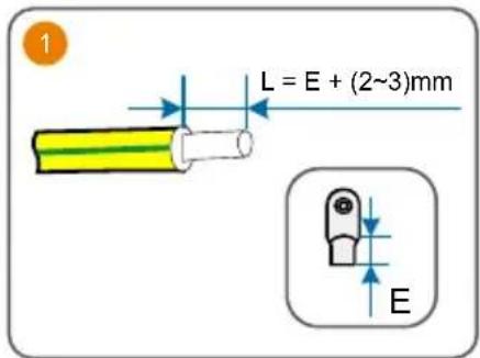
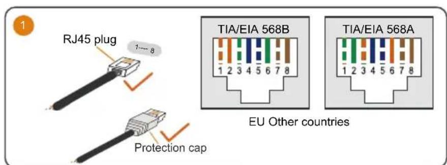
Slotted screwdriver:M4、M2
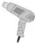
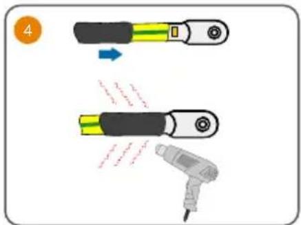
Heat gun
RJ45 Crimping tool
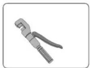
Open-end wrench: 24mm, 35mm
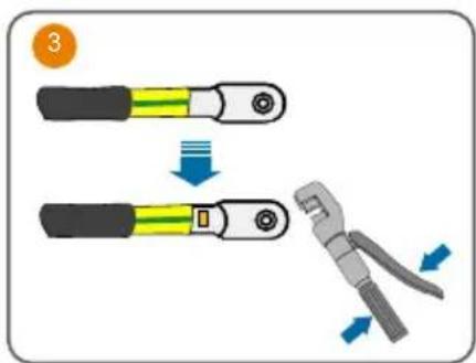
Tube Terminal Crimping
tool
Mounting / Montage / Montaggio / Montage / Montage / Montaz / Montaje / Montagem / Montering
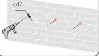
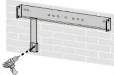
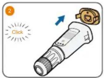
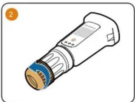
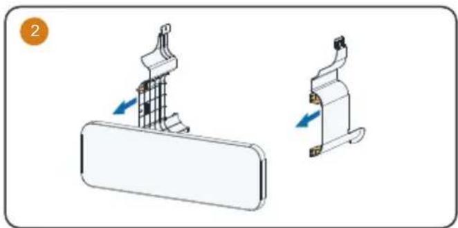
1
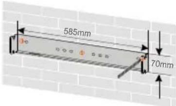
2
The depth of the holes should be about 70 mm.
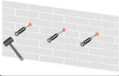
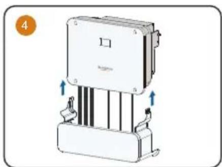
3
4
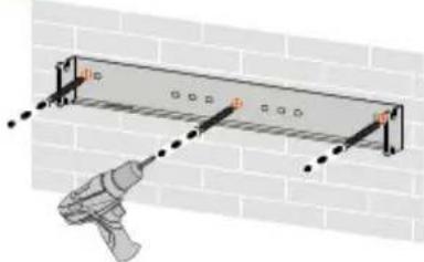
natural_image
Diagram of a utility pole installation with a tool, showing brick wall and measurement markings (no text or symbols)5
natural_image
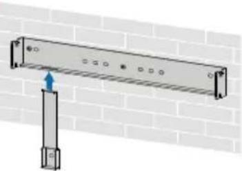
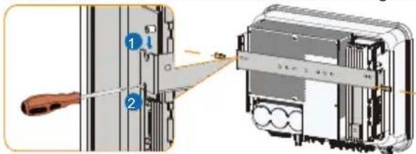
Diagram of a metal beam supported by a vertical support against a brick wall (no text or symbols)6
natural_image
Diagram of a wall-mounted support structure mounted on a brick wall, with a tool inserted (no text or symbols)7
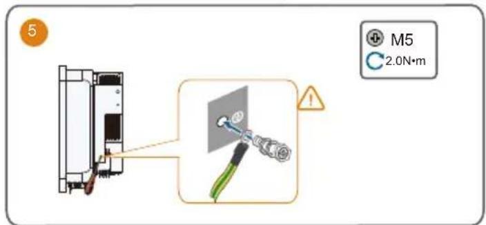
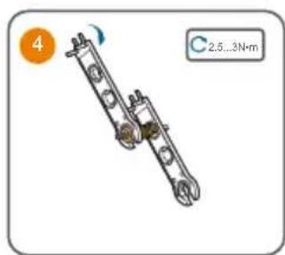
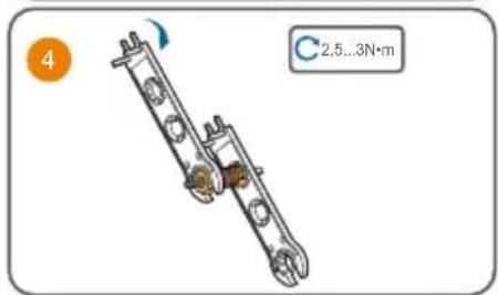
Must use two screw sets to lock both left and right sides.


M5

.0 N.m
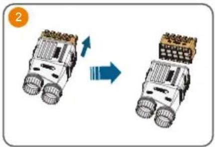
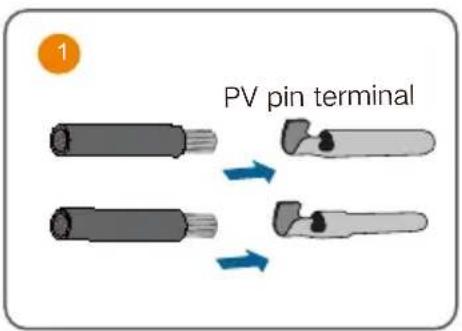
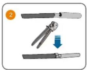
Terminal Description
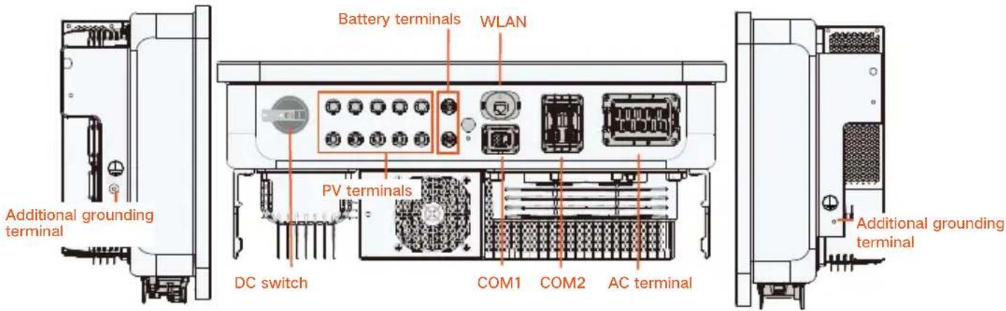
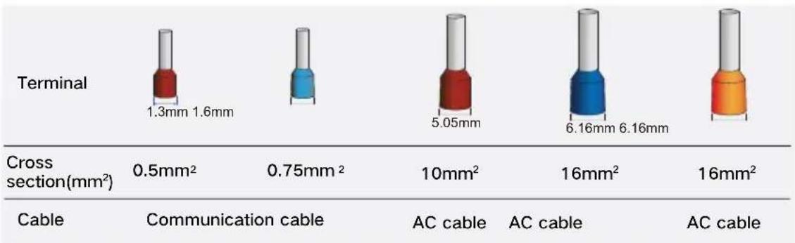
bar
| Category | Terminal (mm²) | Cross section (mm²) | Communication cable (mm²) | AC cable (mm²) | AC cable (mm²) | | :--- | :--- | :--- | :--- | :--- | :--- | | Cable | 1.3 | 0.5 | - | - | - | | Cable | 1.6 | 0.5 | - | - | - | | Cable | 0.75 | 0.75 | - | - | - | | Cable | 5.05 | 10 | - | - | - | | Cable | 16 | 16 | - | - | - | | Cable | 6.16 | 16 | - | - | - | | Cable | 6.16 | 16 | - | - | - | | Cable | 16 | 16 | - | - | - |PE / Erdung / messa a terra / Mise à la terre / Aarding / PE / PE / EP / Skyddsjord
- The cable specification must comply with local regulations (if available). Otherwise, keep it consistent with the PE wire in the AC cable.
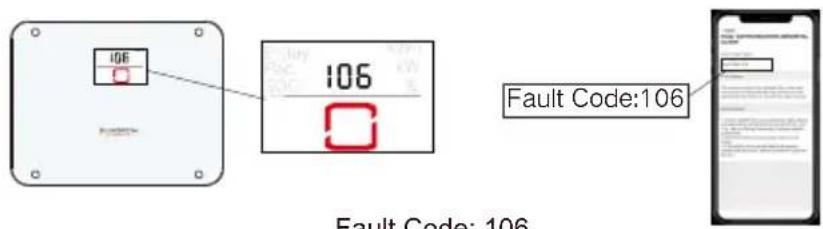
- If mishandled, it may cause a 106 fault. Detailed troubleshooting procedures are outlined below.
Load
Grid
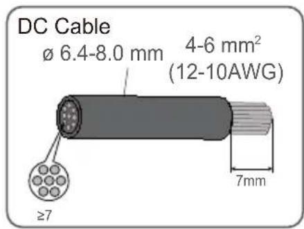
AC Cable
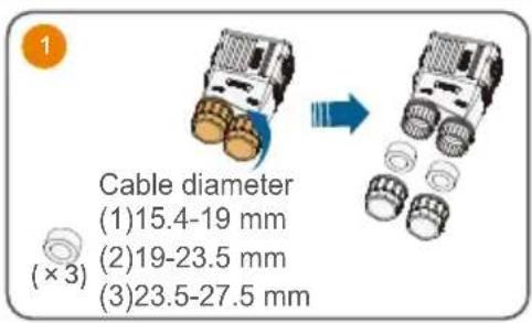
SH5-12T: 14.4-23mm
SH15-25T: 21-27.5mm

SH5-12T: 6-10mm²(10-7AWG)
SH15-25T: 10-16mm²(7-5AWG)
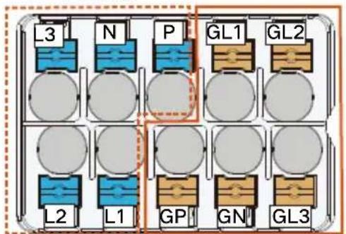
- There are two different markings for the AC wiring terminals, one is the combination of GR, GS, GT, LR, LS, and LT, and the other is the combination of GL1, GL2, GL3, L1, L2, and L3 (as shown above). The actual product should take precedence.
natural_image
Two robotic vehicles with wheels and a grid roof, shown in side-by-side motion (no text or symbols)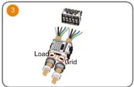
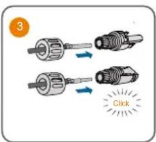
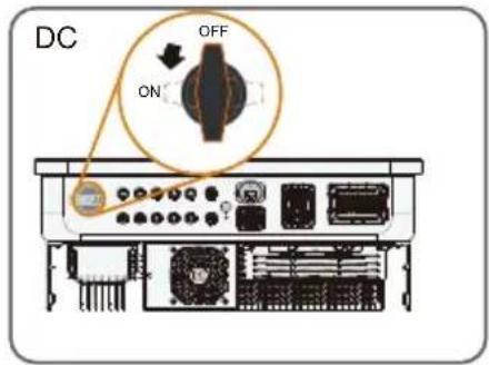
DC
natural_image
Mechanical assembly diagram showing two connected rods with rotating components (no text or symbols)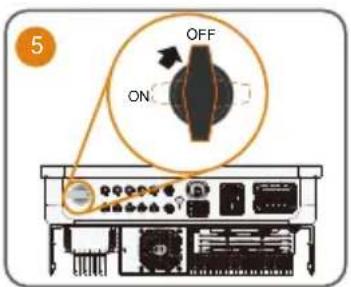
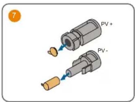

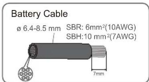
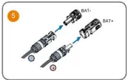
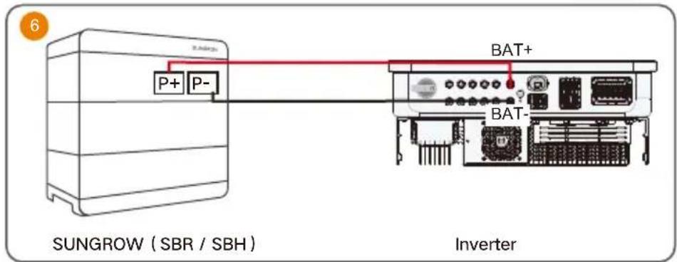
Battery (Power)

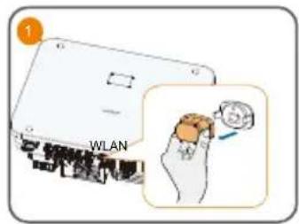
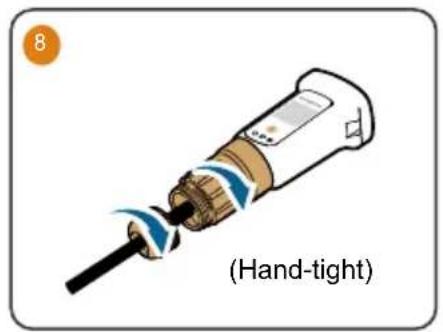
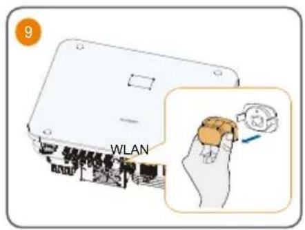
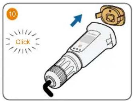
WiNet-S2
• Installation with WLAN communication
Ethernet
natural_image
Illustration of a medical or laboratory device with a blue cap and orange end cap (no text or symbols)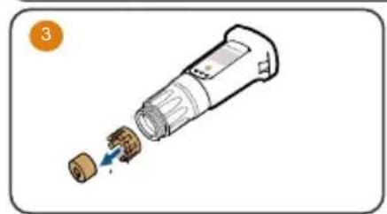
natural_image
Diagram of a device with a plug inserted into a socket (no text or symbols visible)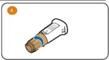
natural_image
Illustration of a cylindrical device with a blue stripe and brown body, labeled with number 4 (no text or symbols on the device itself)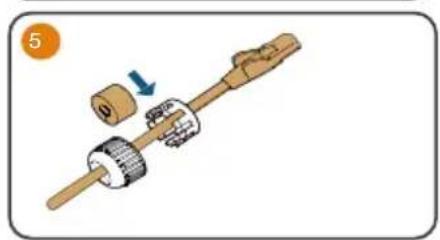
natural_image
Mechanical assembly diagram showing a shaft with gears and a housing, no text or symbols present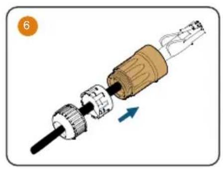
natural_image
Mechanical assembly diagram showing a shaft and gear assembly with directional arrow (no text or symbols)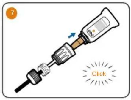
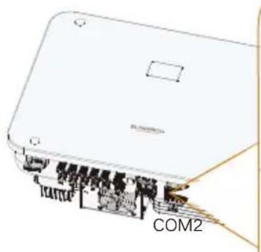
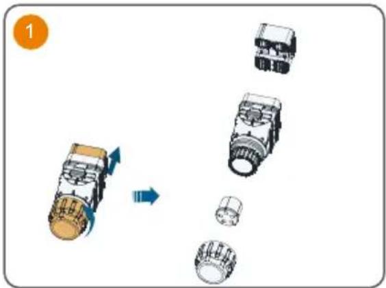
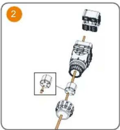
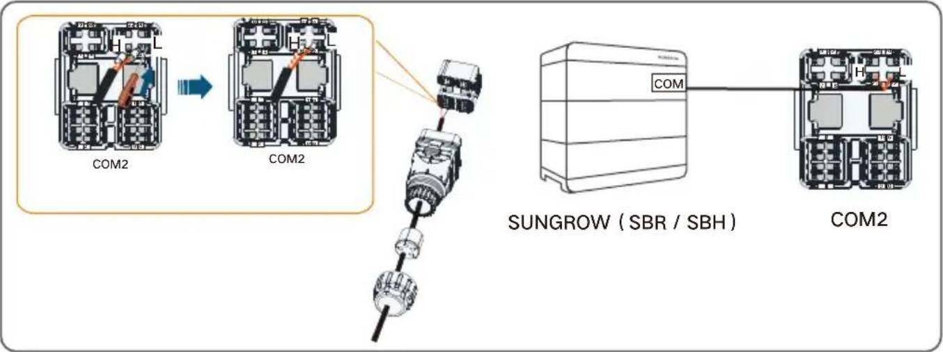
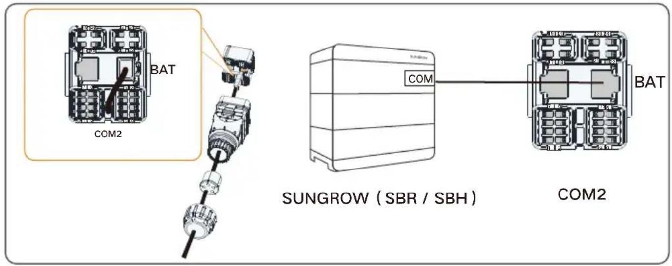
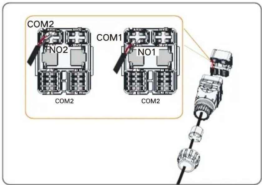
COM2 Terminal Communication Connection
natural_image
Diagram of a device labeled COM2, showing internal components and connections (no readable text or symbols beyond label)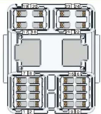
COM2
| DO | COM2 | NO2 |
| COM1 | NO1 | |
| METER | ||
| AI Input | V+ | V- |
| A+ | A- | |
| Meter | A2 | B2 |
| RSD | RSD-1 | RSD-2 |
METER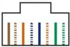 87654321NC NC B2 NC NCA2 NC NC 87654321NC NC B2 NC NCA2 NC NC | RJ45-METER | |||||||
| NC | NC | B2 | NC | NC | A2 | NC | NC | |
| 8 | 7 | 6 | 5 | 4 | 3 | 2 | 1 | |
 87654321NC NC NC NC NC NC L H 87654321NC NC NC NC NC NC L H | RJ45-BAT | |||||||
| NC | NC | NC | NC | NC | NC | L | H | |
| 8 | 7 | 6 | 5 | 4 | 3 | 2 | 1 | |
| Label Description | |
| DO | DO (COM1, NO1):Grounding fault/alarmDO (COM2, NO2):DO connection between inverter and generator |
| AI Input | Reserved |
| Meter(A2,B2) | Connect to the Smart Energy Meter.(If installing a single inverter or if installing the master inverter in a string of parallel inverters.) |
| RSD(RSD-1,RSD-2) | Connect an external switch to enable the emergency stop function |
| BAT | BAT (EN_H, EN_G):Enable the battery with a voltage of 12V.BAT (H, L):To enable the communication between the inverter and the Li-ion battery |
| Logger(A1,B1)* | Connect to the Logger, so as to implement data exchange with PC or other monitoring devices. |
| DRM | "AU"/"NZ": Demand response enabling device (DRED)"IT": interface protection system (SPI)"DE": Ripple Control Receiver (RCR) |
| RJ45-METER(A2,B2) | RJ45 port for communication between the inverter and the Smart Energy Meter |
| RJ45-BAT(H,L) | RJ45 port for communication between the inverter and the battery |
* The length of the RS485 communication cable cannot exceed 1200m (1200m is supported for the default baud rate of 9600 only).
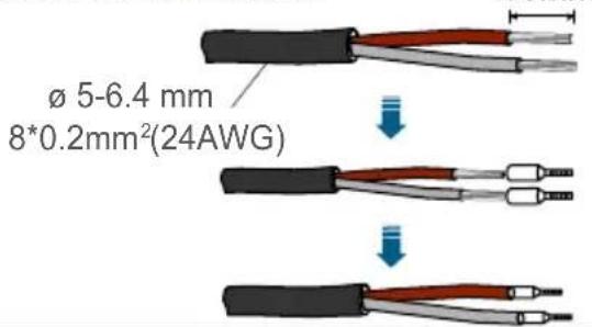
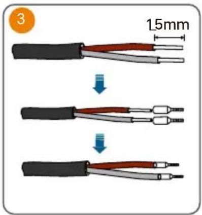
Communication Cable
Single-strand wire:
ø 5-6.4 mm 2*(0.5-0.75) mm²(20-18AWG)

Multi-core multi-strand wire:
Smart Energy Meter Connection :
4
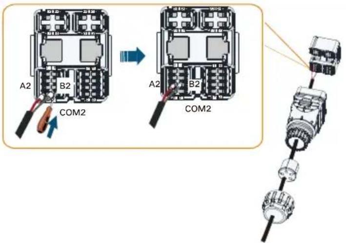
If the communication distance (L) ≤ 10m, use a RS485 communication cable for connection directly; if 10m < L ≤ 50m, add an extra 120Ω resistor to improve the communication quality.
flowchart
graph TD
    A["Motor Switch"] --> B["Motor Load"]
    B --> C["Switch"]
    C --> D["Motor Pulling"]
    style A fill:#f9f,stroke:#333
    style B fill:#ccf,stroke:#333
    style C fill:#cfc,stroke:#333
    style D fill:#fcc,stroke:#333
- If mishandled, it may cause a 514 fault. Detailed troubleshooting procedures are outlined below.
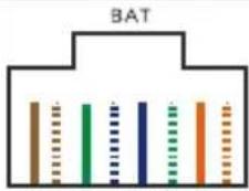
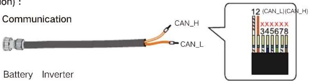
Battery (Communication) :
Method 1: RS485 Communication
flowchart
graph TD
    A["COM2"] --> B["COM2"]
    B --> C["SUNGROW (SBR / SBH)"]
    C --> D["COM2"]
Method 2: RJ45 Communication
natural_image
Illustration of a cylindrical pipe with flanged ends and a central thick band (no text or symbols)Battery Inverter
DO Connection :
DRM Connection :
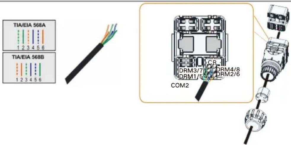
For detailed information on the DRM and RCR functions, including wiring instructions, please refer to the SH5-25T User Manual.
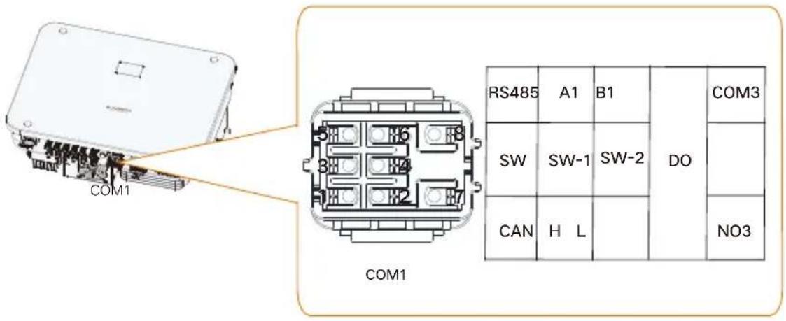
| Label | Description |
| RS485(A1,B1)* | The RS485 communication port is used only for the parallel connection of SUNGROW SH5-25T hybrid inverters. It should not be used for other purposes or the parallel connection of third-party devices. |
| SW(SW-1,SW-2) | Smart switch signal feedback port, used for parallel connection of inverters (≥3 inverters) |
| CAN(H,L) | CAN communication port for parallel connection of inverters |
| DO(COM3,NO3) | Intelligent control switch for parallel connection of inverters (connected the host only) |
**For details on scenarios where multiple inverters are connected in parallel, refer to the SH5-25T Multi-Hybrid System Application Manual. Please contact SUNGROW for further information.
Protective Cover Installation (Optional)
natural_image
Diagram showing two mechanical components with directional arrows indicating movement (no text or symbols)
natural_image
Diagram of a mechanical device with directional arrows indicating movement or force (no text or symbols present)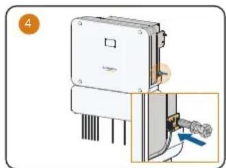
natural_image
Diagram of a mechanical device with a close-up view showing a pipe connection (no text or symbols present)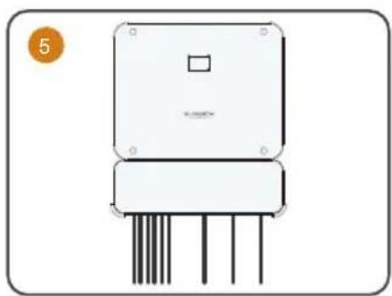
natural_image
Illustration of a rectangular electronic device with four vertical pins and a square top (no text or symbols)

- Wait 5 minutes after completing the previous step before proceeding to the next one.
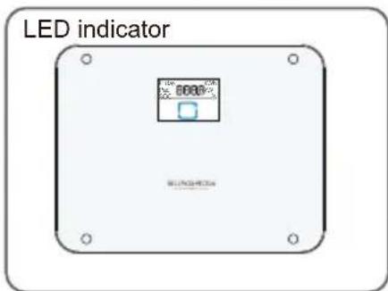
LED indicator / LED-Anzeige / Indicatore LED/ Voyants LED / LED-indicator/ Kontrolki LED / Indicador LED / Indicador de LED / LED-indikator
| LED indicator LED state Definition | ||
 | ON | The inverter is running in the on/off-grid mode. |
| Twinkling | The inverter is at standby or startup state (without on/off-grid operation). | |
 | ON | A system fault has occurred. |
 | OFF | Both the AC and DC sides are powered down. |
Troubleshooting (Fault Code: 514)
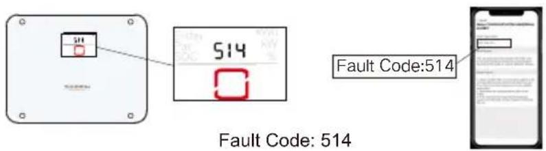
Meter Communication Abnormal Alarm
Step 1: Check whether the communication cables between the inverter and the meter are correctly connected.
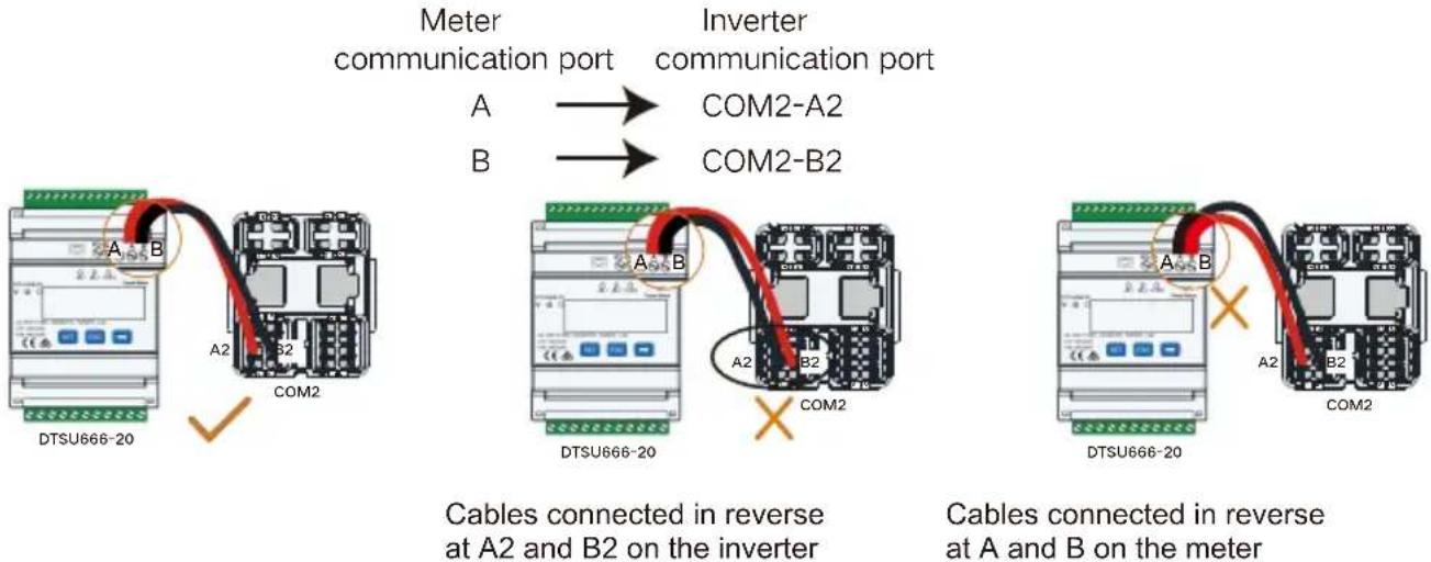
flowchart
graph TD
    A[" meters communication port"] --> B[" Inverter communication port "]
    B --> C[" Cables connected in reverse at A2 and B on the inverter "]
    C --> D[" Cables connected in reverse at A and B on the meter "]
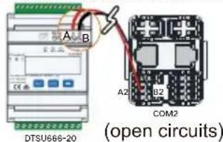
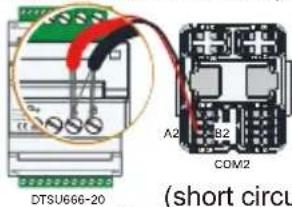
Step 2: If the communication cables are connected correctly, check the communication line for open circuits or short circuits.
Step 3: If the communication wiring is normal, check whether the meter communication address has been modified (the default address is 254).

Steps to check and modify the meter communication address:
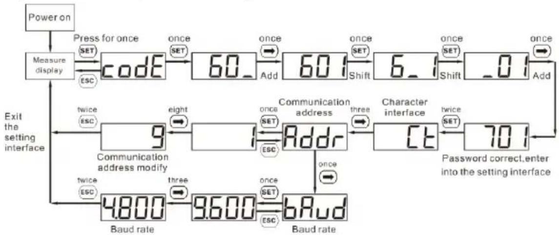
Button description: "SET" represents "confirm" or "cursor shift" (when input digits), "ESC" represents "exit", and "→" represents "add". The password is 701 by default.
flowchart
graph TD
    A["Power on"] --> B["Measure display"]
    B --> C["Code"]
    C --> D["60_"]
    D --> E["Add"]
    E --> F["6_1"]
    F --> G["Shift"]
    G --> H["0_1"]
    H --> I["Add"]
    I --> J["Character interface"]
    J --> K["70_1"]
    K --> L["Password correct, enter into the setting interface"]
    M["Exit the setting interface"] --> N["Baud rate"]
    N --> O["4.800"]
    N --> P["9.600"]
    N --> Q["bRud"]
    Q --> R["Three SET"]
    R --> S["Once SET"]
    S --> T["Address"]
    T --> U["three SET"]
    U --> V["Reset"]
    V --> W["twice SET"]
    W --> X["9"]
    X --> Y["Eight"]
    Y --> Z["Set SET"]
    Z --> AA["Address"]
    AA --> AB["Three SET"]
    AB --> AC["Reset"]
    AC --> AD["twice SET"]
    AD --> AE["70_1"]
    AE --> AF["Password correct, enter into the setting interface"]
When input digits, “SET” can be used as cursor “-” motion button, “→” is “add” button, “ESC” is Exit the programming operation interface or switch to the character interface from digit modification interface, add from the beginning after setting the digit to the maximum value.
Grounding Cable Fault
Step 1: Check whether the PE wire at the LOAD terminal is connected properly in compliance with the standard wiring diagram.
Step 2: Check whether the PE wire at the GRID terminal is connected properly in compliance with the standard wiring diagram.
Step 3: Check whether the external grounding cable of the inverter is connected properly in compliance with the standard wiring diagram.
Australia and New Zealand:
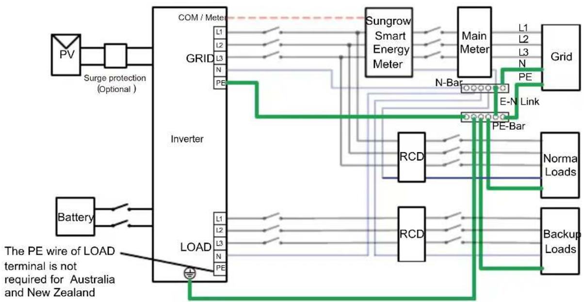
flowchart
graph TD
    PV["PV"] --> SurgeProtection["Surge protection (Optional)"]
    SurgeProtection --> GridGRID["Grid"]
    GridGRID --> Inverter["Inverter"]
    Inverter --> LoadLOAD["Load"]
    LoadLOAD --> Battery["Battery"]
    Battery --> SurgeProtection
    SurgeProtection --> GridGRID
    GridGRID --> Inverter
    Inverter --> LoadLOAD
    LoadLOAD --> PowerOutput["Power Input"]
    PowerOutput --> Sungrow[" Sungrow Smart Energy Meter "]
    Sungrow --> MainMeter["Main Meter"]
    MainMeter --> GridGrid["Grid"]
    GridGrid --> E-N[" E-N Link "]
    E-N --> PE-Bar[" PE-Bar "]
    PE-Bar --> RCD1["RCD"]
    RCD1 --> NormalLoads["Norma Loads"]
    NormalLoads --> PE-Bar
    PE-Bar --> RCD2["RCD"]
    RCD2 --> BackupLoads[" Backup Loads "]
    BackupLoads --> PE-Bar
    PE-Bar --> Inverter
    Inverter --> PowerOutput
    PowerOutput --> SurgeProtection
    SurgeProtection --> PV
    SurgeProtection --> Battery
    PowerOutput --> SurgeProtection
    PowerOutput --> Battery
    PowerOutput --> PowerOutput
Other countries:

flowchart
graph TD
    PV["Power Source"] -->|Surge protection| Grid["Grid"]
    Battery["Battery"] --> Inverter["Inverter"]
    Grid -->|L1 L2 L3 N PE| Com["COM/Meter"]
    Grid -->|RCD| Inverter
    Inverter -->|L1 L2 L3 N PE| Grid
    Inverter -->|RCD| Grid
    Grid -->|Sungrow Smart Energy Meter| MainMeter["Main Meter"]
    MainMeter -->|L1 L2 L3 N PE| Grid
    Inverter -->|RCD| Grid
    Inverter -->|RCD| Grid
    Inverter -->|Normal Loads| BackupLoad["Backup Loads"]
    Inverter -->|PE-Bar| BackupLoad
    Load["Load"] -->|L1 L2 L3 N PE| Inverter
    Load -->|RCD| Grid
    Load -->|PE-Bar| BackupLoad
EN
- Contents may be periodically updated or revised due to product development. The information in this guide is subject to change without notice. In no case shall this guide substitute for the user manual or related notes on the device.
- Make sure to read over, fully understand and strictly follow the detailed instructions of the user manual and other related regulations before installing the equipment. The user manual can be downloaded by visiting the website at http://support.sungrowpower.com/; or it can be obtained by scanning the QR code on the side of the equipment or the back cover of this guide.
- All operations can be performed only by qualified personnel, that must be trained for installation and commissioning of electrical system, as well as dealing with hazards, have knowledge of the manual and of the local regulations and directives.
- Before installation, check that the package contents are intact and complete compared to the packing list. Contact SUNGROW or the distributor in case of any damaged or missing components.
- The cable used must be intact and well insulated. Operation personnel must wear proper personal protective equipment (PPE) all the time.
- Any violation could result in personal death or injury or device damage, and will void the warranty.
Safety
The inverter has been designed and tested strictly according to international safety regulations. Read all safety instructions carefully prior to any work and observe them at all times when working on or with the inverter. Incorrect operation or work may cause:
- injury or death to the operator or a third party;
■ damage to the inverter or other properties.
Please follow the safety instructions related to the PV strings and the utility grid.

DANGER
Lethal voltage!
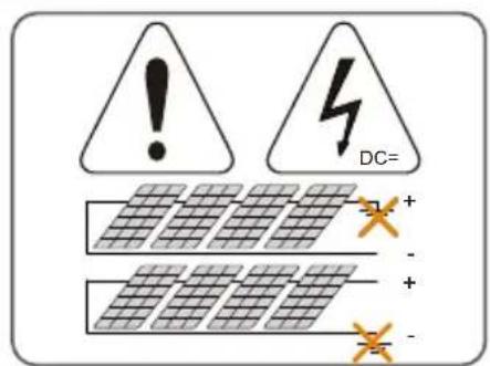
- PV strings will produce electrical power when exposed to sunlight and can cause a lethal voltage and an electric shock.
- Only qualified personnel can perform the wiring of the PV panels.

NOTICE
Danger to life from electric shock due to lethal voltage!
- All electrical connections must be in accordance with local and national standards.
- Only with the permission of the local utility grid company, the inverter can be connected to the utility grid.
Inverter
The warning label on the inverter body are as follows.

Disconnect the inverter from all the external power sources before maintenance!

Danger to life due to high voltages! Do not touch live parts for 10 minutes after disconnection from the power sources.
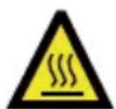
Burn danger due to hot surface that may exceed 60 °C .
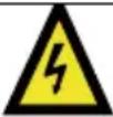 | Danger to life due to high voltages!Only qualified personnel can open and maintain the inverter. |
 | Read the user manual before maintenance! |
 | Do not dispose of the inverter together with household waste. |
 | TÜV mark of conformity. |
 | CE mark of conformity.EU/EEA Importer. |
 | RCM mark of conformity. |
 | Additional grounding point. |
 | RoHS labelingThe product complies with the requirements of the applicable EU directives. |
Users may also attach other warning signs as per the requirements of the local standards or installation specifications.

DANGER
Danger to life from electric shocks due to live voltage
- Do not open the enclosure at any time. Unauthorized opening will void warranty and warranty claims and in most cases terminate the operating license.
- When the enclosure lid is removed, live components can be touched which can result in death or serious injury due to electric shock.
Lethal danger from electric shock due to possibly damaged inverter
- Only operate the inverter when it is technically faultless and in a safe state.
- Operating a damaged inverter can lead to hazardous situations that can result in death or serious injuries due to electric shock.

WARNING
Risk of inverter damage or personal injury
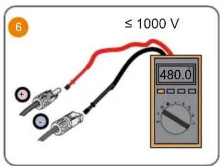
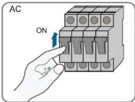
- Do not pull out the PV connectors and AC connector when the inverter is running. Disconnect the AC circuit breaker and set the DC load-break switch of the inverter to OFF. Wait 10 minutes for the internal capacitors to discharge. Verify that there is no voltage or current before pulling any connector.

WARNING
All the warning labels and nameplate on the inverter body:
- must be clearly visible; and
- must not be removed, covered or pasted.

CAUTION
Risk of burns due to hot components!
- Do not touch any hot parts (such as the heat sink) during operation. Only the DC switch can safely be touched at any time.

NOTICE
Only qualified personnel can perform the country setting. Unauthorized alteration may cause:
• A breach of the type-certificate marking.
Risk of inverter damage due to electrostatic discharge (ESD)!
By touching the electronic components, you may damage the inverter. For inverter handling, be sure to:
• avoid any unnecessary touching; and
- wear a grounding wristband before touching any connectors.
Battery

DANGER
Batteries deliver electrical power, resulting in burns or a fire hazard when they are short circuited, or wrongly installed.
Lethal voltages are present in the battery terminals and cables in the inverter. Severe injuries or death may occur if the cables and terminals in the inverter are touched.

NOTICE
Improper settings or maintenance can permanently damage the battery.
Incorrect inverter parameters will lead to the premature aging of battery.
EU Declaration of Conformity
within the scope of the EU directives


The object of the declaration described above is in conformity with the relevant Union harmonisation legislation:
Low Voltage Directive 2014/35/EU (LVD)
Electromagnetic compatibility 2014/30/EU (EMC)
Restriction of the use of certain hazardous substances 2011/65/EU and 2015/863/EU (RoHS)
The manufacturer Sungrow Power Supply Co. Ltd, China hereby confirms that the product SH5T,SH6T,SH8T,SH10T,SH12T complies with the essential requirements and other relevant provisions of Directive 2014/35/EU (LVD), 2014/30/EU (EMC),2011/65/EU and 2015/863/EU (RoHS).The full EU Declaration of Conformity can be found at https://support.sungrowpower.com/PdfDetail?id=1764614550698012674
The communication module that comes with the inverter and the technical parameters of wireless communication are listed in the table below. The model of the communication module actually delivered shall prevail. The EU Declaration of Conformity for the communication module can be found at support.sungrowpower.com.
WiNet-S2:
| Radio technology | WLAN | 802.11b/g/n20/n40 |
| Radio spectrum | 802.11b/g/n20 | 2412 MHz ~ 2472 MHz |
| 802.11n40 | 2422 MHz ~ 2462 MHz | |
| Maximum transmission power | ≤ 20 dBm |
Technical parameters listed above apply to EU countries only.
Security Declaration
For details on the product's network security vulnerability response process and vulnerability disclosure, please scan the QR code on the right or visit the following website:
https://en.sungrowpower.com/security-vulnerability-management
For more information on network security, please refer to the user manual of the communication module or the Data Logger that comes with the product.

Manufacturer :
Sungrow Power Supply Co., Ltd.
No 1699. Xiyou Road,Hefei 230088.P.R.China
For EU only
https://support.sungrowpower.com/PdfDetail?id=1764615232347910145
https://en.sungrowpower.com/security-vulnerability-management
Sungrow Power Supply Co., Ltd.
No 1699. Xiyou Road, Hefei 230088. P.R. China
Nur für die EU
IT
https://en.sungrowpower.com/security-vulnerability-management
Produttore :
Sungrow Power Supply Co., Ltd.
No 1699. Xiyou Road, Hefei 230088. R. P. Cinese
Solo per l'UE
Importatore UE/SEE: Sungrow Deutschland GmbH
https://en.sungrowpower.com/security-vulnerability-management
Fabricant :
Sungrow Power Supply Co., Ltd.
No 1699. Xiyou Road, Hefei 230088. P.R. China
Fabrikant :
Sungrow Power Supply Co., Ltd.
No 1699. Xiyou Road, Hefei 230088. P.R. China
Alleen voor de EU
Producent:
Sungrow Power Supply Co., Ltd. No 1699. Xiyou Road, Hefei 230088. ChRL Tylko na eksport do UE Importer w UE/EOG: Sungrow Deutschland GmbH Balanstraße 59, 81541 Monachium, Niemcy
ES
https://en.sungrowpower.com/security-vulnerability-management
Fabricante :
Sungrow Power Supply Co., Ltd.
No 1699. Xiyou Road, Hefei. 230088 R. P. China
Solo para la UE
Importador UE/EEE: Sungrow Deutschland GmbH
Balanstraße 59, 81541 München, Alemania
PT
https://en.sungrowpower.com/security-vulnerability-management
Fabricante :
Sungrow Power Supply Co., Ltd.
No 1699. Xiyou Road, Hefei 230088.P.R.China
Apenas para a UE
Importador UE/EEE: Sungrow Deutschland GmbH
Balanstraße 59, 81541 München, Alemanha
SV
Tillverkare :
Sungrow Power Supply Co., Ltd.
No 1699. Xiyou Road,Hefei 230088. Kina
Endast EU
More information in the QR code or at http://support.sungrowpower.com/
- Quick Installation Guide
- Backup Wiring Diagram (For AU / NZ) Loads Connected to the Grid :
- Whole Home Backup Wiring Diagram (For AU / NZ) Loads Connected to the Inverter :
- Whole Home Backup Wiring Diagram (For Other Countries) Loads Connected to the Inverter:
- Backup Wiring Diagram (For TT system) Loads Connected to the Grid :
- Battery (Power)
- WiNet-S2
- Ethernet
- Communication Cable
- Protective Cover Installation (Optional)
- EN
- Safety
- DANGER
- NOTICE
- Inverter
- WARNING
- CAUTION
- Battery
- EU Declaration of Conformity
- Security Declaration
- IT
- ES
- PT
- SV
Brand : Sungrow
Model : SH25T
Category : Power inverter