
S450S - Power inverter Sungrow - Free user manual and instructions
Find the device manual for free S450S Sungrow in PDF.

| Brand | Sungrow |
| Model | S450S |
| Product Type | Micro-inverter |
| Power Supply | Photovoltaic strings (DC) and electrical grid (AC) |
| Protections | Overvoltage protection, electrostatic discharge protection, overheating protection |
| Safety Standards | CE, TÜV, RoHS, Anatel (No. 23376-23-11568) |
| Communication | WiFi 802.11b/g/n (2.4 GHz, max power 20 dBm) |
| Installation | Qualified personnel only, personal protective equipment (PPE) |
| Warning | Do not open the enclosure; do not touch hot parts (>60 °C) |
| Disconnection | Wait 10 min after power-off before disconnecting connectors |
| Cooling | Wait 30 min before intervention after shutdown |
| Compliance | Directive RED 2014/53/EU, LVD 2014/35/EU, EMC 2014/30/EU, RoHS 2011/65/EU |
| Maintenance | Check for absence of voltage before intervention, wear protective gloves |
| Repairability | Only qualified personnel may open the inverter; any unauthorized opening voids warranty |
| Manual Available | Download from support.sungrowpower.com |
| Warranty | Voided in case of unauthorized opening |
Frequently Asked Questions - S450S Sungrow
User questions about S450S Sungrow
0 question about this device. Answer the ones you know or ask your own.
Ask a new question about this device
Download the instructions for your Power inverter in PDF format for free! Find your manual S450S - Sungrow and take your electronic device back in hand. On this page are published all the documents necessary for the use of your device. S450S by Sungrow.
USER MANUAL S450S Sungrow
Quick Installation Guide
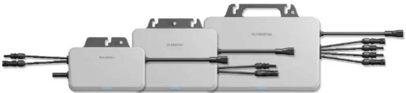
Single-Phase Microinverter
S450S / S800S / S1000S / S1600S
natural_image
Exterior view of two white solar panel modules with black connectors and wiring, no visible text or symbolsEN
- Contents may be periodically updated or revised due to product development. The information in this guide is subject to change without notice. In no case shall this guide substitute for the user manual or related notes on the device.
- Make sure to read over, fully understand and strictly follow the detailed instructions of the user manual and other related regulations before installing the equipment. The user manual can be downloaded by visiting the website at http://support.sungrowpower.com/; or it can be obtained by scanning the QR code on the front of the microinverter or the back cover of this guide.
- All operations can be performed only by qualified personnel, that must be trained for installation and commissioning of electrical system, as well as dealing with hazards, have knowledge of the manual and of the local regulations and directives.
- Before installation, check that the package contents are intact and complete compared to the packing list. Contact SUNGROW or the distributor in case of any damaged or missing components.
- The cable used must be intact and well insulated. Operation personnel must wear proper personal protective equipment (PPE) all the time.
- Any violation could result in personal death or injury or device damage, and will void the warranty.
- Incorporates product approved by Anatel under number 23376-23-11568.
Safety
The inverter has been designed and tested strictly according to international safety regulations. Read all safety instructions carefully prior to any work and observe them at all times when working on or with the inverter. Incorrect operation or work may cause:
- Injury or death to the operator or a third party.
• Damage to the inverter or other properties.
Please follow the safety instructions related to the PV strings and the utility grid.
Security Declaration
- To learn more about the product network security vulnerability response process and vulnerability disclosure, please scan the QR code below or visit the following website: https://en.sungrowpower.com/security-vulnerability-management


DANGER
Lethal voltage!
- PV strings will produce electrical power when exposed to sunlight and can cause a lethal voltage and an electric shock.
- Only qualified personnel can perform the wiring of the PV panels.
- All electrical connections must be in accordance with local and national standards.
- Only with the permission of the local utility grid company, the inverter can be connected to the utility grid.
- Do not open the enclosure at any time. Unauthorized opening will void warranty and warranty claims and in most cases terminate the operating license.
- When the enclosure lid is removed, live components can be touched which can result in death or serious injury due to electric shock.
Lethal danger from electric shock due to possibly damaged inverter
- Only operate the inverter when it is technically faultless and in a safe state.
- Operating a damaged inverter can lead to hazardous situations that can result in death or serious injuries due to electric shock.

WARNING
Risk of inverter damage or personal injury
- Do not pull out the PV connectors and AC connector when the inverter is running. Disconnect the AC circuit breaker. Wait 10 minutes for the internal capacitors to discharge. Verify that there is no voltage or current before pulling any connector.
- Even after the microinverter has been stopped, it may still be hot and cause burns. Wait 30min until the microinverter cools down, and then perform operations on it wearing protective gloves.

WARNING
All the warning labels and nameplate on the inverter body:
- Must be clearly visible.
- Must not be removed, covered or pasted.

CAUTION
Risk of burns due to hot components!
- Do not touch any hot parts (such as the heat sink) during operation.

NOTICE
Only qualified personnel can perform the country setting. Unauthorized alteration may cause:
• A breach of the type-certificate marking.
Risk of inverter damage due to electrostatic discharge (ESD)!
By touching the electronic components, you may damage the inverter. For inverter handling, be sure to:
- Avoid any unnecessary touching.
- Wear a grounding wristband before touching any connectors.
MicroInverter
The warning label on the inverter body are as follows.
Danger to life due to high voltages! Only qualified personnel can open and maintain the inverter.

Disconnect the inverter from all the external power sources before maintenance!

Read the user manual before maintenance!
CE mark of conformity. EU/EEA Importer.

TÜV mark of conformity.
Burn danger due to hot surface that may exceed 60 °C.
Do not touch live parts for 10 minutes after disconnection from the power sources.
Do not dispose of the inverter together with household waste.

RoHS labeling The product complies with the requirements of the applicable EU directives.

UTE C15-712-1 Warning label for installation.
Manufacturer :
Sungrow Power Supply Co., Ltd.
No 1699. Xiyou Road, Hefei 230088. P.R. China
For EU only
EU Declaration of Conformity


within the scope of the EU directives
The object of the declaration described above is in conformity with the relevant Union harmonisation legislation:
The radio Equipment Directive 2014/53/EU (RED)
Low Voltage Directive 2014/35/EU (LVD)
Electromagnetic compatibility 2014/30/EU (EMC)
Restriction of the use of certain hazardous substances 2011/65/EU and 2015/863/EU (RoHS)
The manufacturer Sungrow Power Supply Co., Ltd., China hereby confirms that the product S450S,S800S,S1000S,S1600S complies with the essential requirements and other relevant provisions of Directives 2014/53/EU (RED), 2014/35/EU(LVD) and 2014/30/EU (EMC),2011/65/EU and 2015/863/EU (RoHS).The full EU Declaration of Conformity can be found at https://support.sungrowpower.com/PdfDetail?id=1790188194723446785
The communication module that comes with the inverter and the technical parameters of wireless communication are listed in the table below. The model of the communication module actually delivered shall prevail. The EU Declaration of Conformity for the communication module can be found at support.sungrowpower.com.
Microinverter(WIFI):
Radio technology
WLAN 802.11b/g/n
Radio spectrum
2412 MHz \~ 2472MHz
Maximum transmission power
≤ 20 dBm
Technical parameters listed above apply to EU countries only.
FR

DANGER
Tension mortelle !
Sungrow Power Supply Co., Ltd.
No 1699. Xiyou Road,Hefei 230088.P.R.China

GEFAHR
Sungrow Power Supply Co., Ltd.
Nr. 1699. Xiyou Road, Hefei 230088. P.R. China
Nur für die EU
https://support.sungrowpower.com/PdfDetail?id=1790190511526952961
https://en.sungrowpower.com/security-vulnerability-management


GEVAAR
Sungrow Power Supply Co., Ltd.
No 1699. Xiyou Road, Hefei 230088.P.R.China
Alleen voor de EU
* The images shown here are for reference. The actual product and quantity are based on delivery.
flowchart
graph TD
    A["Solar Panel 1"] --> B["Central Processing Unit"]
    C["Solar Panel 2"] --> B
    D["Solar Panel 3"] --> B
    E["Solar Panel 4"] --> B
    F["Power Supply"] --> G["Switch"]
    B --> H["Component 1"]
    B --> I["Component 2"]
    B --> J["Component 3"]
    B --> K["Component 4"]
    B --> L["Component 5"]
    B --> M["Component 6"]
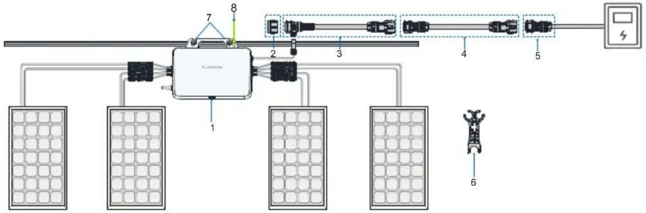
| NO. | Definition Model | Description | |
| Microinverter1 | S450S/S800S/S1000S/S1600S | Included in the scope of delivery as standard equipment. | |
| 2 | Sealing cap for T type connector | - | Users place separate orders. Used to seal off the unused port on the T-type connector. |
| 3 | AC cable with T type connector_25 | - | Users place separate orders.Used to connect two microinverters. |
| 4 | AC extension cable_25 | - | Optional. Used when the distance between two microinverters exceeds 2.8m. |
| 5 | AC connector_male | - | Users place separate orders.Used to connect the microinverter to the power distribution box. |
| 6 | AC connector unlock tool | - | Users place separate orders. Used to disconnect two T-type AC trunk cables, or disconnect the T-type AC trunk cable from the microinverter. |
| 7 | M8 fixing screw M8 | Prepared by users. Used to fix the microinverter. | |
| 8 | Grounding cable | Recommended cross-section of the cable:2.5 mm2 | Prepared by users.Used for external grounding of Microinverter. |
| Grounding screw | M4 | Included in the scope of delivery. |
* Note: Only the power distribution box is allowed to be connected to the AC grid-connected side.
Installation Tool / Werkzeuge zur Installation / Outil d'installation / Montagegereedschap
natural_image
Simple illustration of a sharpened pencil (no text or symbols on the pencil itself)

natural_image
Illustration of a wire cutter tool (no text or symbols on the tool itself)
natural_image
Slotted screwdriver with black handle and gray body (no text or symbols on the tool itself)Mounting location / Emplacement de montage / Montageort / Montageplaats
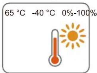
The average temperature approximately 20 cm around the microinverter should be taken as its operating temperature. The temperature and humidity should meet the requirements below:


natural_image
Illustration of a thermometer and a snowflake (no text or symbols)
Product Appearance&Dimensions / Apparence et dimensions du produit / Erscheinungsbild und Abmessungen des Produkts / Uiterlijk en afmetingen van product
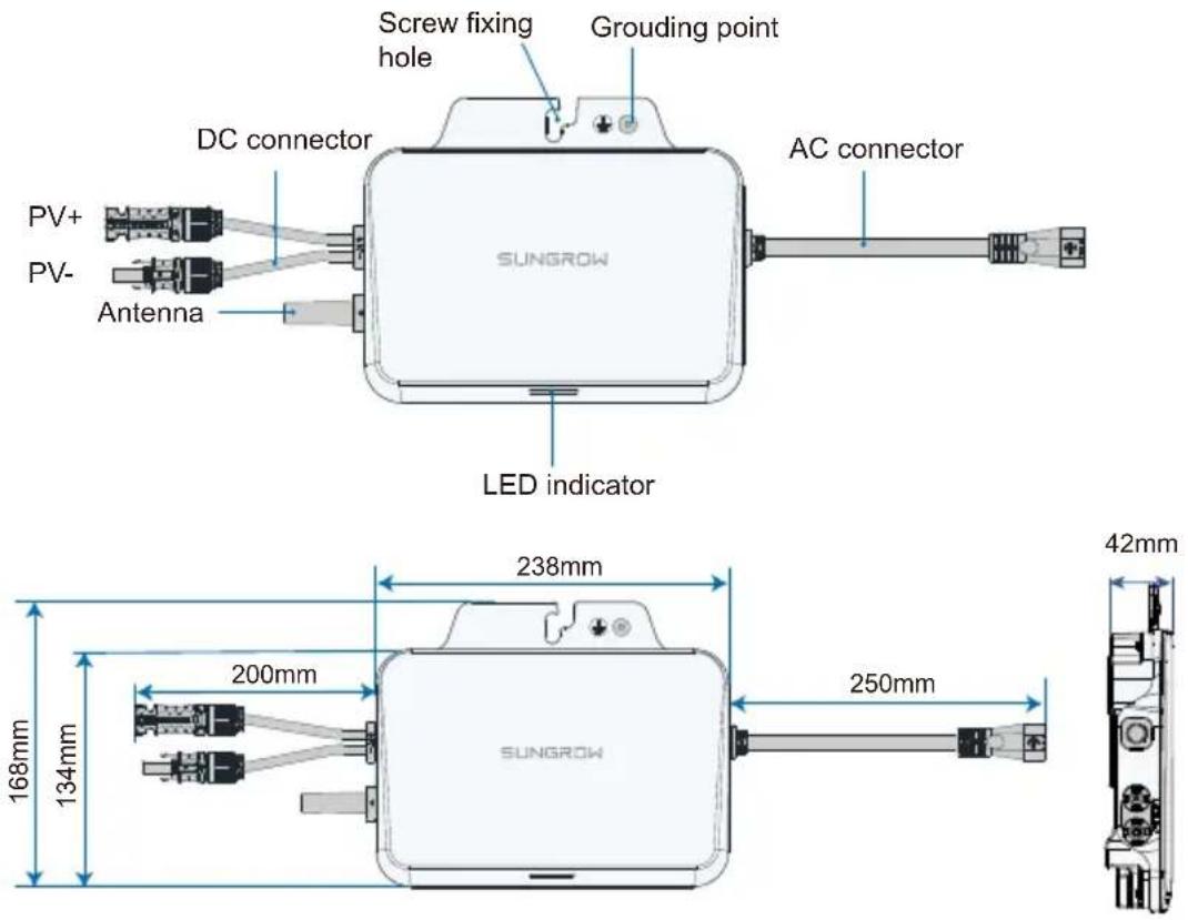
S450S:
S800S/S1000S:

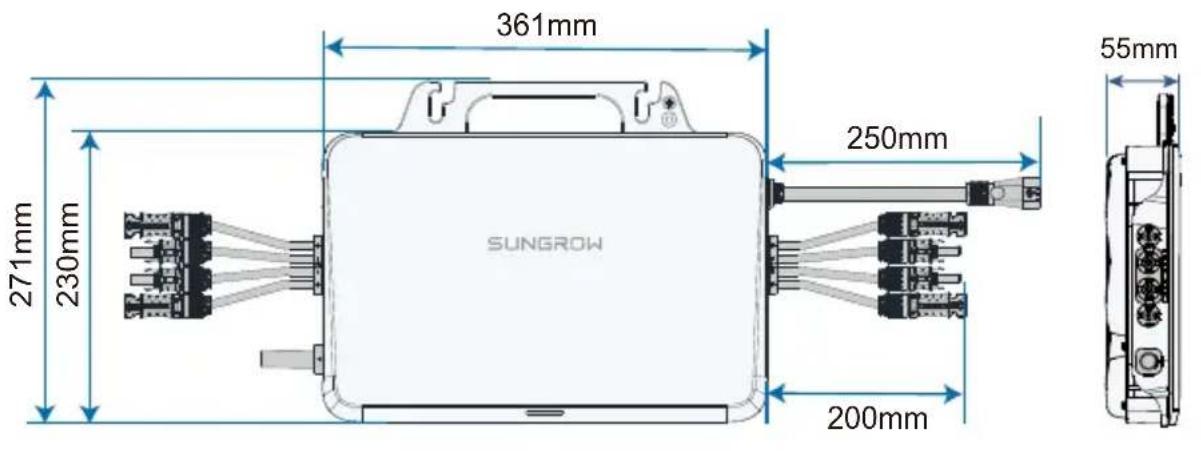
S1600S:
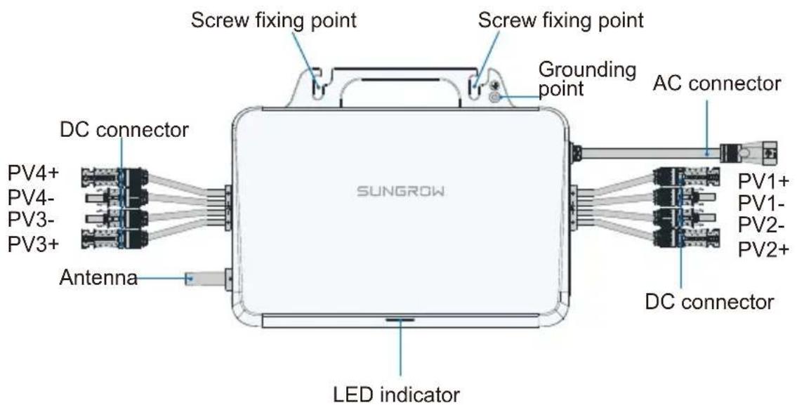
- Do not bump, squeeze, or bend its connectors or Wi-Fi antenna when handling the microinverter. Deformation or damage may impair the device's performance or normal operation.
- Do not lift the cable by hand when handling the device. The S450S, S800S and S1000S microinverters do not have handles. You may move the device by gripping the groove on its back.
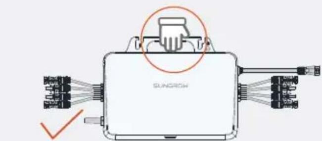
(Recommended)

(Prohibited)
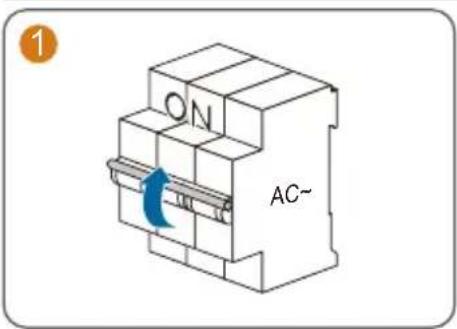
1
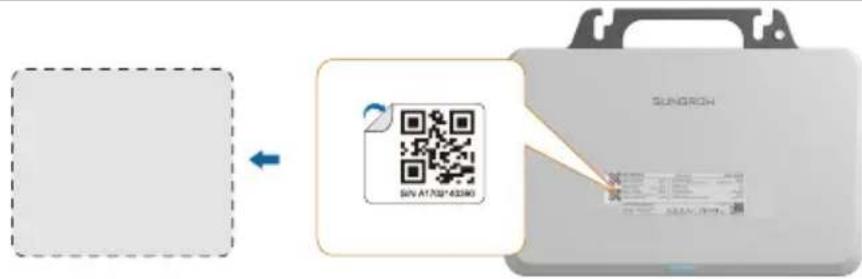
Remove one of the two identical QR code labels on the device enclosure, and stick it inside the dotted box on the left (if multiple microinverters are used, put their QR codes on the blank page before this Guide's back cover). This QR code is used for iSolarCloud related operations.
2

Nut
(not included in the scope of delivery)
3
4
natural_image
Technical diagram of a Sunrow airship or sensor module with wiring and components (no text labels)
M8

9.0N·m
Washers should be added to the M8 screws by the user separately. Washers with an inner diameter of 8.5 mm and a thickness of 2.5 mm are recommended; while the outer diameter of the washer must be greater than 24 mm.
- Avoid placing the device in direct sunlight. It is recommended to install it under the PV module.
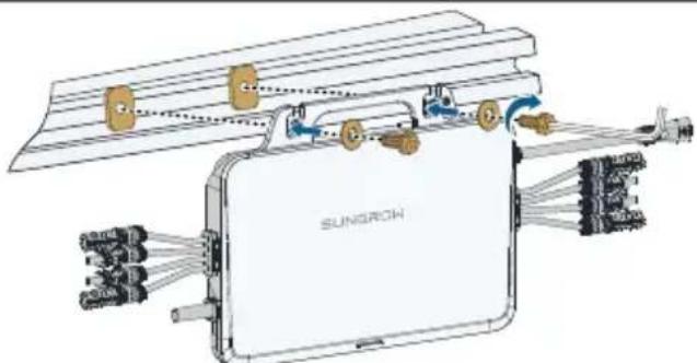
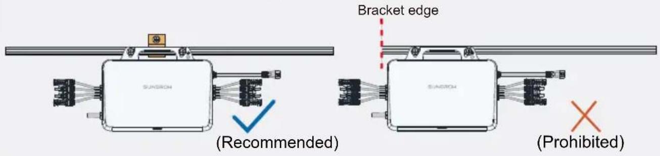
- It is recommended that the inverter fixing screws be installed around the roof frame fixing hook.
- Do not mount the microinverter on the edge of the bracket.
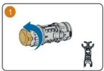
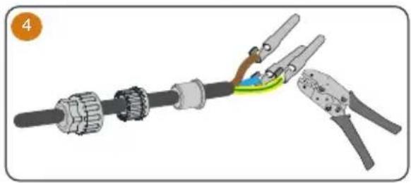
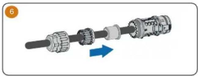
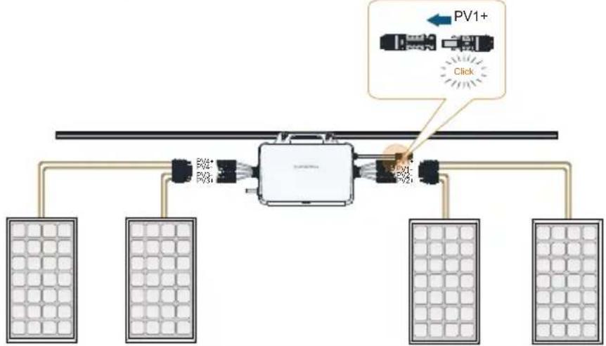
Attach AC Male Connector / Fixez le connecteur CA mâle / Bringen Sie den AC-Stecker an / Sluit het mannetje van de AC-connector aan
natural_image
Illustration of a mechanical device with a blue arrow indicating rotation and a separate view of a tower-like structure (no text or symbols)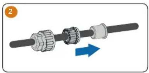
natural_image
Mechanical assembly diagram showing a shaft and gear mechanism with a blue directional arrow (no text or symbols)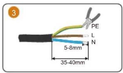
natural_image
Illustration of a cable being inserted into two different types of pliers (no text or symbols present)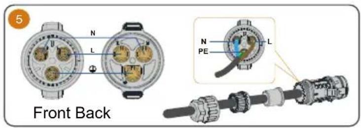
natural_image
Mechanical assembly diagram showing a shaft and gear mechanism with a blue arrow indicating direction (no text or symbols)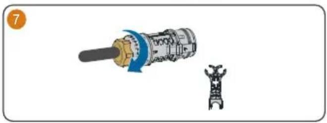
natural_image
Diagram showing a mechanical component being inserted into a housing, with no visible text or symbols.Observe the marks on the terminals when making cables and ensure the polarity is correct. Otherwise, after connecting to the power distribution box, the microinverter may not operate properly, the house's circuit may trip, and it may even result in personal injuries.
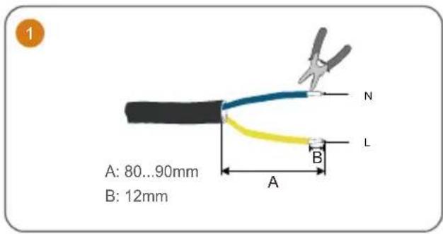
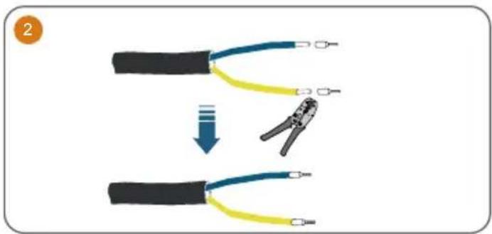
Wiring Steps / Procédure de câblage / Verkabelungsschritte / Bedradingsprocedure
1 Connect the external grounding cable.
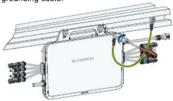
It is recommended to make a protective ground connection. Lack of protective grounding or unreliable grounding may lead to personal injuries.
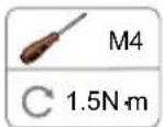
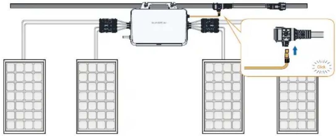
2 Connect the DC connectors, make sure there is a PV module connected to PV1.
flowchart
graph TD
    A["Power Supply Panel"] --> B["Control Unit"]
    B --> C["Power Supply Panel"]
    C --> D["Solar Panels"]
    style A fill:#f9f,stroke:#333
    style B fill:#ccf,stroke:#333
    style C fill:#cfc,stroke:#333
    style D fill:#fcc,stroke:#333
    note right of B: PV1+ Click
WARNING
The PV1 channel acts as the host and must be connected with PV module. If it is left unconnected, the system may report a fault and cannot operate properly.
CAUTION
- When connecting the DC connectors, make sure the order of the connectors corresponds properly to the actual positions of PV modules at the site, to facilitate the later setup of the physical layout of the plant.
- If not all of the DC connectors of the microinverter are connected to PV modules, use IP67 waterproof plugs to close off the unused connectors. The waterproof plugs should be prepared by the user.
- If the PV module is located too far away from the microinverter, a DC extension cable is needed. The user needs to make the extension cable first.
- Ensure the PV cables are connected with correct polarity. Otherwise, the microinverter may not operate properly.
• PV modules cannot be connected in series.
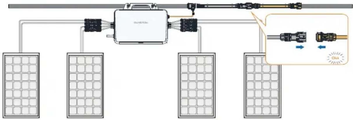
3
Connect the AC connector.
4
(Optional) Connecting extension cables.
flowchart
graph TD
    A["Central Device"] --> B["Panel 1"]
    A --> C["Panel 2"]
    A --> D["Panel 3"]
    A --> E["Panel 4"]
    B --> F["Panel 5"]
    C --> G["Panel 6"]
    D --> H["Panel 7"]
    E --> I["Panel 8"]
    F --> J["Click Button"]
    G --> J
    H --> J
    I --> J
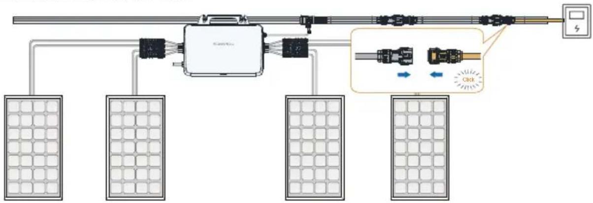
5
Connect the AC male connector.
flowchart
graph TD
    A["Solar Panel"] --> B["Central Device"]
    C["Power Supply"] --> B
    B --> D["Control Switch"]
    D --> E["Output"]
    style B fill:#f9f,stroke:#333
    style E fill:#bbf,stroke:#333
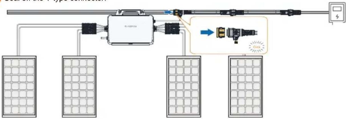
4
Seal off the T-type connector.
flowchart
graph TD
    A["Central Device"] --> B["Panel 1"]
    A --> C["Panel 2"]
    A --> D["Panel 3"]
    A --> E["Panel 4"]
    F["Control Unit"] --> G["Switch"]
    H["Display"] --> I["Power Supply"]
    J["Input"] --> K["Control Button"]
    L["Click"] --> M["Output"]
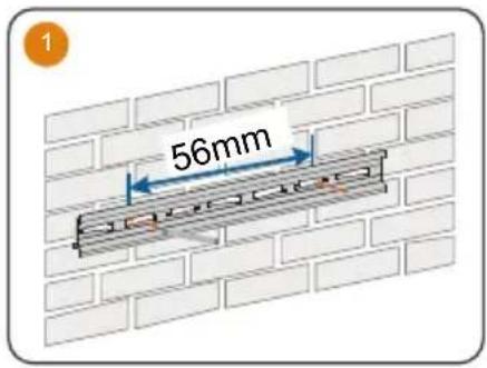
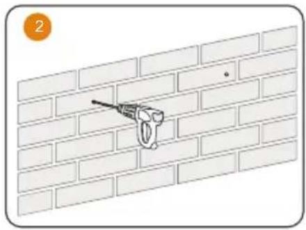
- Mounted on a Wall
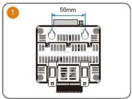
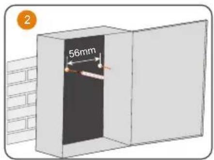
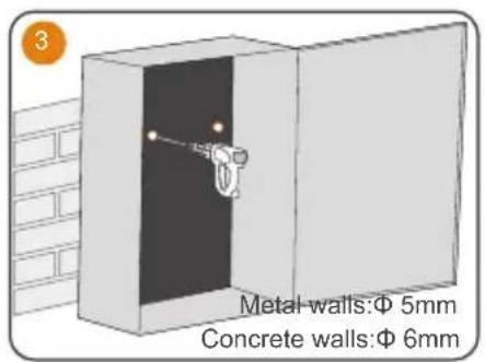
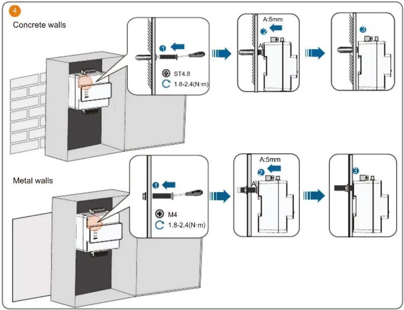
flowchart
graph TD
    A["Concrete walls"] --> B["1: ST4.8 1.8-2.4(N·m)"]
    B --> C["A:5mm"]
    C --> D["2"]
    D --> E["3"]
    E --> F["Metal walls"]
    F --> G["M4 1.8-2.4(N·m)"]
    G --> H["A:5mm"]
    H --> I["2"]
    I --> J["3"]
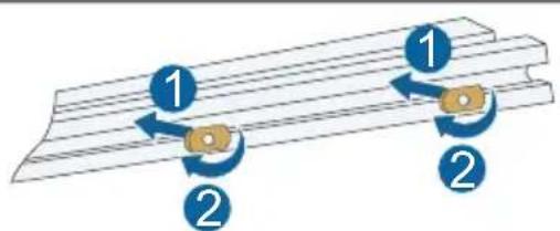
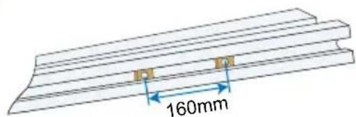
- Mounted on a Guide Rail
natural_image
Diagram of a pipe clamp securing a brick wall, no text or symbols present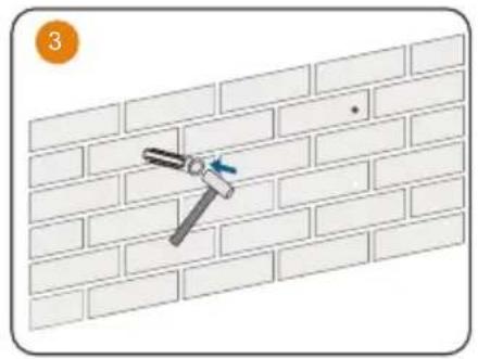
natural_image
Diagram of a hammer securing a brick wall, showing alignment and angle (no text or symbols)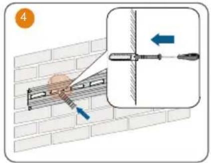
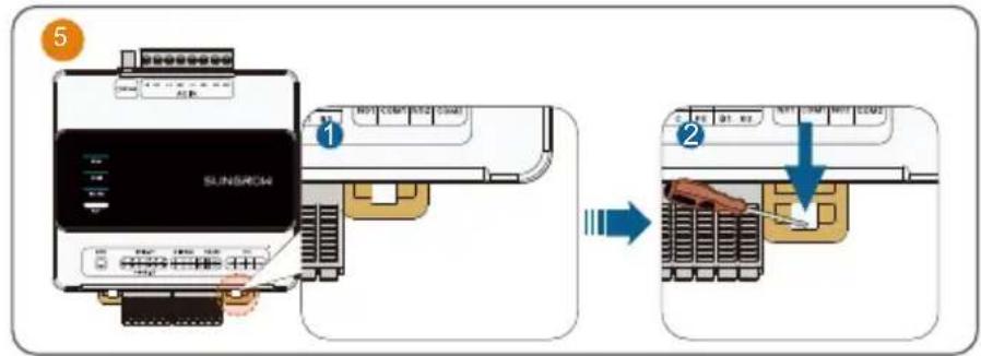
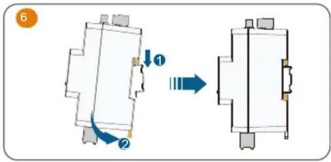
flowchart
graph TD
    A["Step ①"] --> B["Step ②"]
    B --> C["Arrow to Right"]
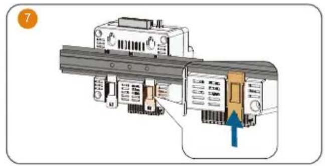
natural_image
Diagram of a mechanical device with internal components and a blue arrow indicating a specific section (no text or symbols present)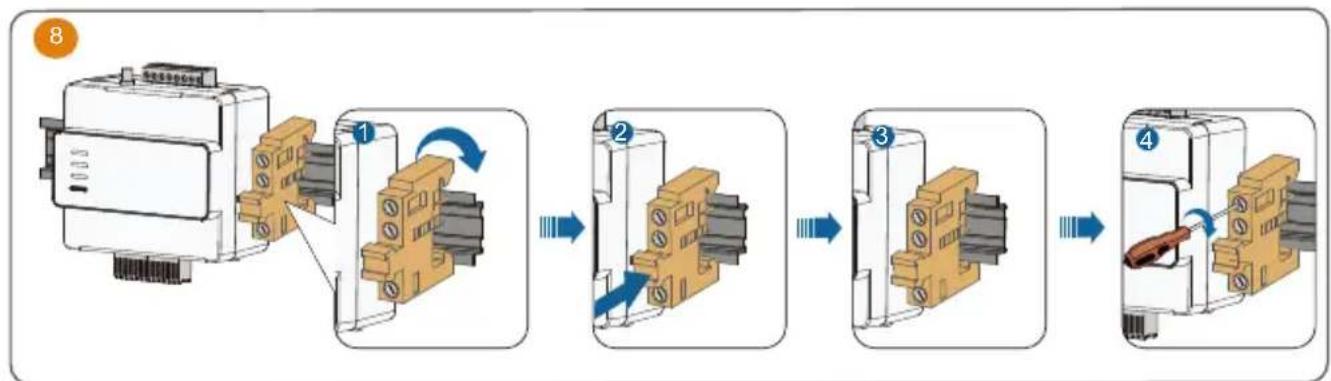
flowchart
graph LR
    A["Motor with attached components"] --> B["Step 1: Rotation of switch"]
    B --> C["Step 2: Inserted switch"]
    C --> D["Step 3: Inspection of switch"]
    D --> E["Step 4: Inspection of switch"]
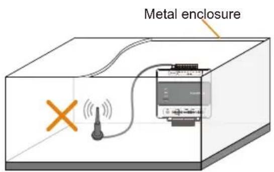
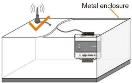
- Antenna Installation
- AC and GRID. CT connection
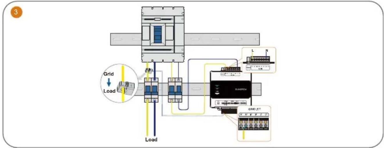
flowchart
graph TD
    A["Load"] --> B["Grid"]
    B --> C["Control Module 1"]
    B --> D["Control Module 2"]
    B --> E["Control Module 3"]
    C --> F["Grid_C7"]
    D --> G["Grid_C6"]
    E --> H["Grid_C5"]
    I["Grid"] --> J["Load"]
    K["Load"] --> L["Grid_C6"]
    M["Grid_C5"] --> N["Grid_C4"]
The iHomeManager comes with three CTs. Connect only one CT to the microinverter.
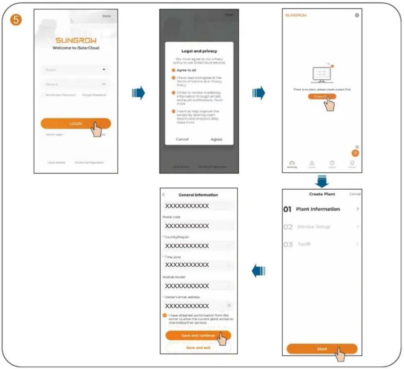
Commissioning / Mise en service / Inbetriebnahme / Inbedrijfstelling
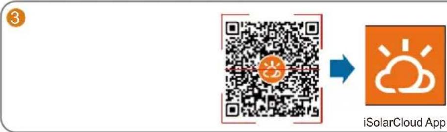
• To fully utilize the features of the iSolarCloud App, please grant it access to your camera, location, and network when you first open the App.
- Connect only one mobile phone to the microinverter's hotspot at a time. Otherwise, it may lead to a conflict issue.
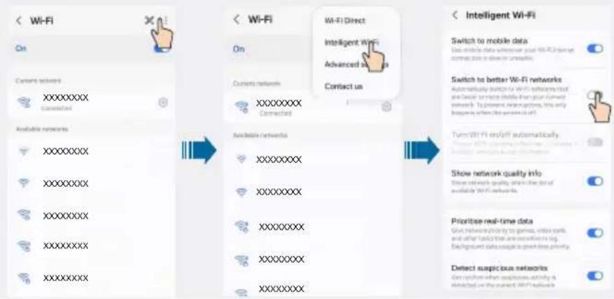
- It is suggested to turn off auto network switching on the mobile phone so that it can stay connected to the microinverter's hotspot. Otherwise, the phone may switch to a stronger Wi-Fi signal automatically and its
Samsung mobile phone as an example:
4


flowchart
graph TD
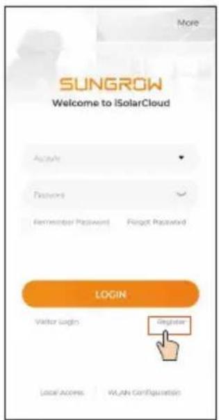
A["SUNGROW\nWelcome to iSolarCloud\nScene\nFailed\nRemember Password2\n UAE Password"] --> B["LOCAL ACCESS\n |\NIAin Configuration"]
B --> C["Legal and privacy\nYou must agree to our privacy\npolicy to use SolarCloud services\nAgree to all\nI have read and agree to the\nTerms of Service and Privacy\nPolicy\nI'd like to receive marketing\ninformation through emails\nand push notifications. Read more\nI want to help improve the\nservice by sharing crash\ndReports and analytics data.\nRead more\nCancel\nAgree"]
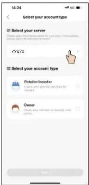
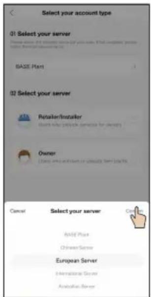
C --> D["Create Plant\nCancel\n01 Plant Information\nDevice Setup\nTariff"]
D --> E["General information\nXXXXXXXXXX\nPostal code\XXXXXXXXXX\n*Country/Region\XXXXXXXXXX\n*Time zone\XXXXXXXXXX\nModule model\XXXXXXXXXX\n*Owner's email address\XXXXXXXXXX\nI have obtained authorization from the\nowner to allow the current plant access to\channel/partner services.\nSave and continue\nSave and exit"]
E --> F["Start"]
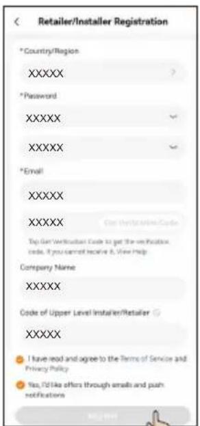
Parameter Description
| *Plant Name | Enter the plant name. |
| *Plant Type | Select the plant type. |
| *PV Installation Power (kWp) | Enter the installed power. |
| *Detailed Address | The location of the plant. |
| *City | The city where the plant is located. |
| Postal Code | The postal code of the place where the plant is located. |
| *Country/Region | The country (region) where the plant is located. |
| *Time Zone | The time zone of the place where the plant is located. |
| Module Model | The model of the PV module actually used in the plant. |
| *Owner's Email Address | Enter the owner's email address. |
| *Grid-connection Type | Set the grid-connection type for the plant. |
| Grid-connected Date | Shows the current date by default. |
| Plant Image | Upload an image of the plant. |
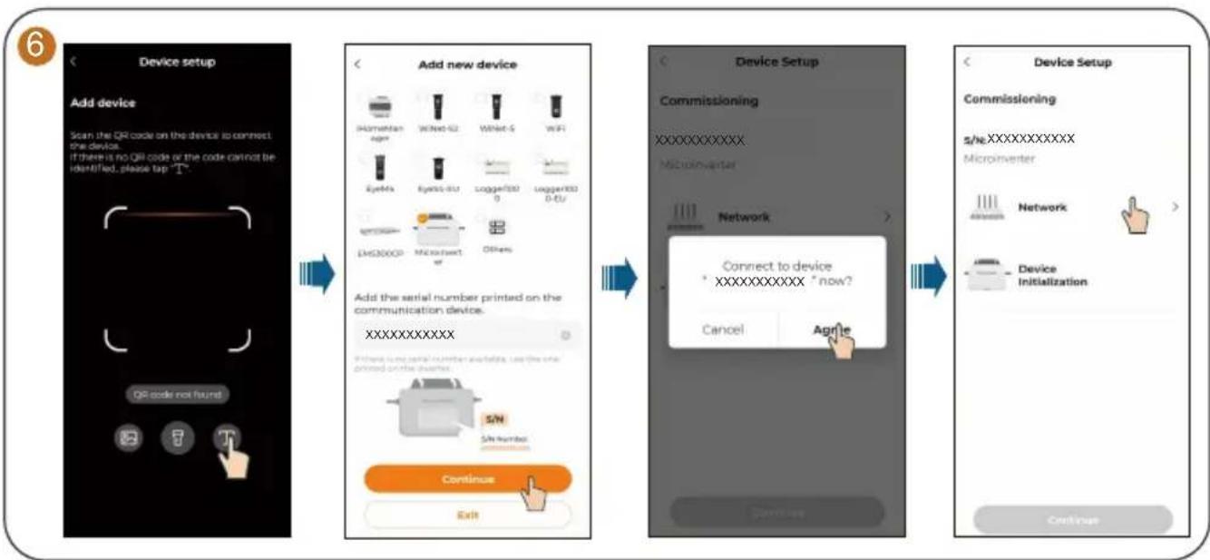
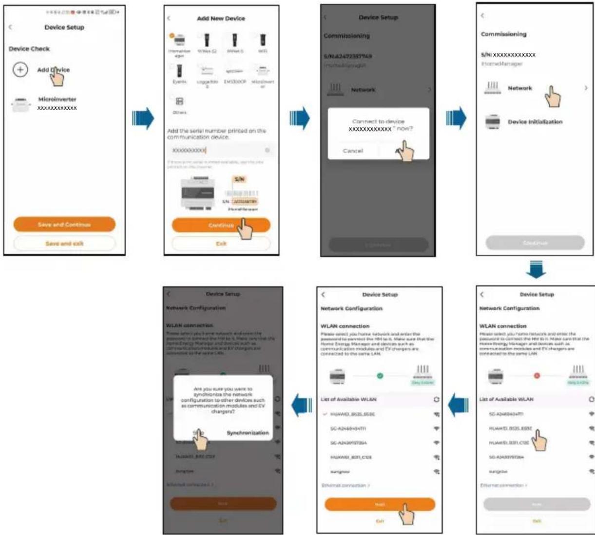
flowchart
graph LR
    A["Device setup"] --> B["Add new device"]
    B --> C["Network Setup"]
    C --> D["Device Setup"]

    subgraph Add new device
        E["Add device: Scan the QR code on the device to connect the device. If there is no QR code or the code cannot be identified, please tap 'T''"]
        F["Add device: QR code not found"]
        G["Add device: Email: Emails"]
        H["Add device: Email: WiFi"]
        I["Add device: Email: Loggers/ISO 0"]
        J["Add device: Loggers/ISO 0-EU"]
        K["Add device: Microinverter"]
        L["Add device: Others"]
        M["Add device: Add the serial number printed on the communication device. XXXXXXXXXXXX"]
        N["Add device: Primary lung serial number protocols used the site printed on the patches"]
        O["Add device: Continue"]
        P["Add device: Exit"]
    end

    subgraph Network Setup
        Q["Network Setup: Connect to device *XXXXXXXXXX * now?"]
        R["Network Setup: Cancel"]
        S["Network Setup: Agri'e"]
        T["Network Setup: Continue"]
    end

    subgraph Device Setup
        U["Device Setup: Commissioning"]
        V["Device Setup: Commissioning"]
        W["Device Setup: s/he.XXXXXXXXXX"]
        X["Device Setup: Microinverter"]
        Y["Device Setup: Network"]
        Z["Device Setup: Device Initialization"]
    end
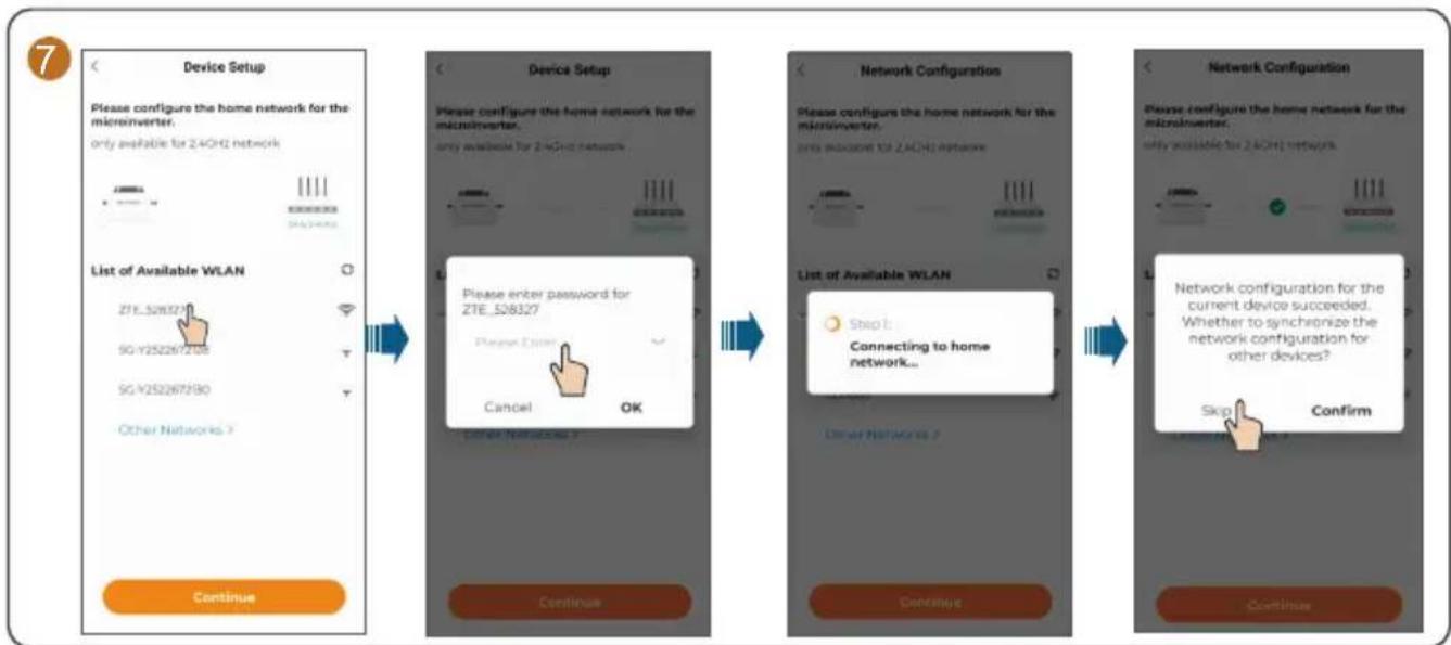
flowchart
graph LR
    A["Device Setup"] --> B["Device Setup"]
    B --> C["Network Configuration"]
    C --> D["Network Configuration"]

    subgraph Device Setup
        E["Please configure the home network for the microinverter.<br>only available for 2.4GHz network"]
        F["ZTE_528327<br>SG-Y252267208"]
        G["SG-Y252267290"]
        H["Other Networks ?"]
        I["Continue"]
    end

    subgraph Network Configuration
        J["Please config the home network for the microinverter.<br>only available for 2.4GHz networks"]
        K["Step 1: Connecting to home network..."]
        L["Stop"] --> M["Confirm"]
        N["Skip"] --> O["Continue"]
    end

    subgraph Network Configuration
        P["Please config the home network for the microinverter.<br>only available for 2.4GHz networks"]
        Q["Network configuration for the current device succeeded.<br>Whether to synchronize the network configuration for other devices?"]
        R["Skip"] --> S["Confirm"]
        T["Continue"]
    end
- If there is one microinverter only, you can choose "SKIP". The network configuration is then completed.
- If there are multiple microinverters, you can choose "CONTINUE" to complete the network configuration for other microinverters. For details, see Step 8.Microinverters for which network settings are synchronized in this step will be added to the plant's device list simultaneously.
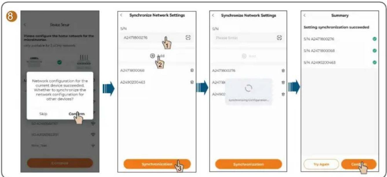
flowchart
graph LR
    A["Device Setup"] --> B["Please configure the home network for the microinvasion.<br>only available for 2.6GHz networks"]
    B --> C{Network configuration for the current device succeeded.
Whether to synchronize the network configuration for other devices?}
    C --> D["Skip Confirm"]
    D --> E["Synchronize Network Settings"]
    E --> F{S/N
A2471800276
Add}
    F --> G{S/N
A2471800068
A2490200463}
    G --> H["Synchronization"]
    H --> I{S/N
Please Enter!}
    I --> J{S/N
A2471800276
Add}
    J --> K{S/N
A2471800068
A2490200463}
    K --> L["Synchronization"]
    L --> M{S/N
A2471800276
Add}
    M --> N{S/N
A2471800068
A2490200463}
    N --> O["Synchronization"]
    O --> P{S/N
A2471800276
Add}
    P --> Q{S/N
A2471800068
A2490200463}
    Q --> R["Synchronization"]
    R --> S{S/N
A2471800276
Add}
    S --> T{S/N
A2471800068
A2490200463}
    T --> U["Synchronization"]
    U --> V{S/N
A2471800276
Add}
    V --> W{S/N
A2471800068
A2490200463}
    W --> X["Synchronization"]
    X --> Y{S/N
A2471800276
Add}
    Y --> Z{S/N
A2471800068
A2490200463}
    Z --> AA["Synchronization"]
    AA --> AB{S/N
A2471800276
Add}
    AB --> AC{S/N
A2471800068
A2490200463}
    AC --> AD["Synchronization"]
    AD --> AE{S/N
A2471800276
Add}
    AE --> AF{S/N
A2471800068
A2490200463}
    AF --> AG["Synchronization"]
    AG --> AH{S/N
A2471800276
Add}
    AH --> AI{S/N
A2471800068
A2490200463}
    AI --> AJ["Synchronization"]
    AJ --> AK{S/N
A2471800276
Add}
    AK --> AL{S/N
A2471800068
A2490200463}
    AL --> AM["Synchronization"]
    AM --> AN{S/N
A2471800276
Add}
    AN --> AO{S/N
A2471800068
A2490200463}
    AO --> AP["Synchronization"]
    AP --> AQ{S/N
A2471800276
Add}
    AQ --> AR{S/N
A2471800068
A2490200463}
    AR --> AS["Synchronization"]
    AS --> AT{S/N
A2471800276
Add}
    AT --> AU{S/N
A2471800068
A2490200463}
    AU --> AV["Synchronization"]
    AV --> AW{S/N
A2471800276
Add}
    AW --> AX{S/N
A2471800068
A2490200463}
    AX --> AY["Synchronization"]
    AY --> AZ{S/N
A2471800276
Add}
    AZ --> BA{S/N
A2471800068
A2490200463}
    BA --> BB["Synchronization"]
    BB --> BC{S/N
A2471800276
Add}
    BC --> BD{S/N
A2471800068
A2490200463}
    BD --> BE["Synchronization"]
    BE --> BF{S/N
A2471800276
Add}
    BF --> BG{S/N
A2471800068
A2490200463}
    BG --> BH["Synchronization"]
    BH --> BI{S/N
A2471800276
Add}
    BI --> BJ{S/N
A2471800068
A2490200463}
    BJ --> BK["Synchronization"]
    BK --> BL{S/N
A2471800276
Add}
    BL --> BM{S/N
A2471800068
A2490200463}
    BM --> BN["Synchronization"]
    BN --> BO{S/N
A2471800276
Add}
    BO --> BP{S/N
A2471800068
A2490200463}
    BP --> BQ["Synchronization"]
    BQ --> BR{S/N
A2471800276
Add}
    BR --> BS{S/N
A2471800068
A2490200463}
    BS --> BT["Synchronization"]
    BT --> BU{S/N
A2471800276
Add}
    BU --> BV{S/N
A2471800068
A2490200463}
    BV --> BW["Synchronization"]
    BW --> BX{S/N
A2471800276
Add}
    BX --> BY{S/N
A2471800068
A2490200463}
    BY --> BZ["Synchronization"]
    BZ --> CA{S/N
A2471800276
Add}
    CA --> CB{S/N
A2471800068
A2490200463}
    CB --> CC["Synchronization"]
    CC --> CD{S/N
A2471800276
Add}
    CC --> CE{S/N
A2471800068
A2490200463}
    CE --> CF["Synchronization"]
    CF --> CG{S/N
A2471800276
Add}
    CF --> CH{S/N
A2471800068
A2490200463}
    CH --> CI["Synchronization"]
    CI --> CJ{S/N
A2471800276
Add}
    CJ --> CK{S/N
A2471800068
A2490200463}
    CK --> CL["Synchronization"]
    CL --> CD["Summary"]
When you change the router, please set up the network connection again. The steps are: log in to the iSolarCloud App, tap the WLAN Configuration, and select the home network to connect to it.
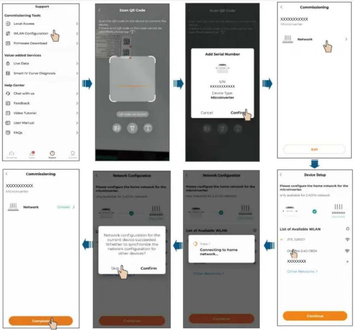
flowchart
graph TD
    A["Support"] --> B["Commissioning Tools"]
    B --> C["Scan QR Code"]
    C --> D["Scan QR Code on device to connect the devices"]
    D --> E["Add Serial Number"]
    E --> F["Device Setup"]
    F --> G["Device Setup for home network"]

    subgraph Support
        B1["Local Access"] --> B2["WLAN Configuration"] --> B3["Firmware Download"]
        B4["Live Data"] --> B5["Smart IV Curve Diagnosis"] --> B6["Help Center"] --> B7["Chat with us"] --> B8["Feedback"] --> B9["Video Tutorial"] --> B10["User Manual"] --> B11["FAQs"] --> B12["Completed"]
        B12 --> B13["Complete"]
    end

    subgraph Commissioning
        C1["Microinverter"] --> C2["Network"] --> C3["Completed"]
    end

    subgraph Network Configuration
        C4["Please configure the home network for the microinverter. only establish for 2.4GHz network"] --> C5["Network configuration for the current device succeeded. Whether to synchronize the network configuration for other devices?"]
        C5 --> C6["Skip"] --> C7["Confirm"]
        C7 --> C8["Continue"]
    end

    subgraph Network Configuration
        C9["Please configure the home network for the microinverter. only available for 2.4GHz network"] --> C10["List of Available WLAN"]
        C10 --> C11["Step 1: Connecting to home network..."]
        C11 --> C12["Other Networks"]
        C12 --> C13["Continue"]
    end

    subgraph Device Setup
        C12 --> C13
        C13 --> C14["List of Available WLAN"]
        C14 --> C15["Initiate 24GHz network"]
        C15 --> C16["Next Step 24GHz"]
        C16 --> C17["Next Step 24GHz"]
        C17 --> C18["Next Step 24GHz"]
        C18 --> C19["Next Step 24GHz"]
        C19 --> C20["Next Step 24GHz"]
        C20 --> C21["Next Step 24GHz"]
        C21 --> C22["Next Step 24GHz"]
        C22 --> C23["Next Step 24GHz"]
        C23 --> C24["Next Step 24GHz"]
        C24 --> C25["Next Step 24GHz"]
        C25 --> C26["Next Step 24GHz"]
        C26 --> C27["Next Step 24GHz"]
        C27 --> C28["Next Step 24GHz"]
        C28 --> C29["Next Step 24GHz"]
        C29 --> C30["Next Step 24GHz"]
        C30 --> C31["Next Step 24GHz"]
        C31 --> C32["Next Step 24GHz"]
        C32 --> C33["Next Step 24GHz"]
        C33 --> C34["Next Step 24GHz"]
        C34 --> C35["Next Step 24GHz"]
        C35 --> C36["Next Step 24GHz"]
        C36 --> C37["Next Step 24GHz"]
        C37 --> C38["Next Step 24GHz"]
        C38 --> C39["Next Step 24GHz"]
        C39 --> C40["Next Step 24GHz"]
        C40 --> C41["Next Step 24GHz"]
        C41 --> C42["Next Step 24GHz"]
        C42 --> C43["Next Step 24GHz"]
        C43 --> C44["Next Step 24GHz"]
        C44 --> C45["Next Step 24GHz"]
        C45 --> C46["Next Step 24GHz"]
        C46 --> C47["Next Step 24GHz"]
        C47 --> C48["Next Step 24GHz"]
        C48 --> C49["Next Step 24GHz"]
        C49 --> C50["Next Step 24GHz"]
        C50 --> C51["Next Step 24GHz"]
        C51 --> C52["Next Step 24GHz"]
        C52 --> C53["Next Step 24GHz"]
        C53 --> C54["Next Step 24GHz"]
        C54 --> C55["Next Step 24GHz"]
        C55 --> C56["Next Step 24GHz"]
        C56 --> C57["Next Step 24GHz"]
        C57 --> C58["Next Step 24GHz"]
        C58 --> C59["Next Step 24GHz"]
        C59 --> C60["Next Step 24GHz"]
        C60 --> C61["Next Step 24GHz"]
        C61 --> C62["Next Step 24GHz"]
        C62 --> C63["Next Step 24GHz"]
        C63 --> C64["Next Step 24GHz"]
        C64 --> C65["Next Step 24GHz"]
        C65 --> C66["Next Step 24GHz"]
        C66 --> C67["Next Step 24GHz"]
        C67 --> C68["Next Step 24GHz"]
        C68 --> C69["Next Step 24GHz"]
        C69 --> C70["Next Step 24GHz"]
        C70 --> C71["Next Step 24GHz"]
        C71 --> C72["Next Step 24GHz"]
        C72 --> C73["Next Step 24GHz"]
        C73 --> C74["Next Step 24GHz"]
        C74 --> C75["Next Step 24GHz"]
    end
9
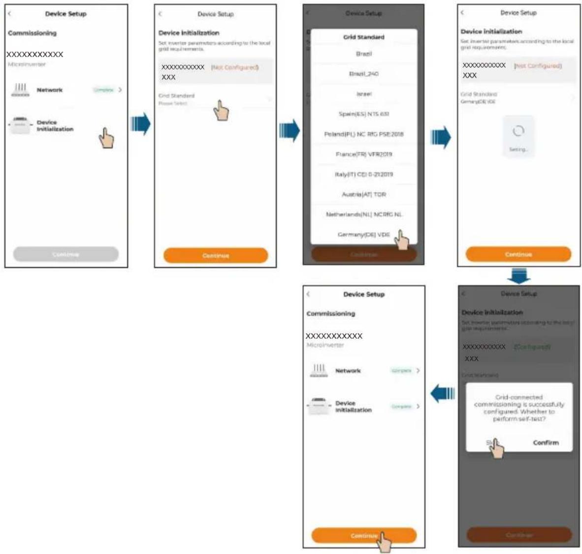
flowchart
graph TD
    A["Device Setup Commissioning\nXXXXXXXXXX\nMicroInverter"] --> B["Device Setup Device Initialization\nSet Inverter parameters according to the local grid requirements.\nXXXXXXXXXX (Not Configured)\nXXX"]
    B --> C["Device Setup Grid Standard\nBrazil\nBrazil_240\nIsrael\nSpain(ES) N15 692\nPoland(PL) NC RIG PSE2018\nFrance(FR) VFR2019\nItaly(IT) CDI 0-212019\nAustria(AT) TCR\nNetherlands(NL) NCRIG NL\nGermany(DE) VDE\nContinues"]
    C --> D["Device Setup Device Initialization\nSet Inverter parameters according to the local grid requirements.\nXXXXXXXXXX (Not Configured)\nXXX"]
    D --> E["Device Setup Grid Standard\nGermany(DE) IDE\nSetting..."]
    E --> F["Device Setup Commissioning\nXXXXXXXXXX\nMicroInverter"]
    F --> G["Device Setup Grid-Connected Commissioning is successfully configured. Whether to perform self-test?\nSign Confirm"]
    G --> H["Device Setup Continues"]
10 Optional
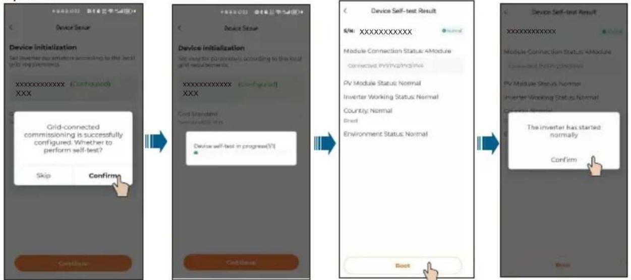
flowchart
graph LR
    A["Device Setup"] --> B["Device Initialization"]
    B --> C["Grid-Connected Commissioning is successfully configured. Whether to perform self-test?"]
    C --> D["Device Self-test Result"]
    D --> E["Module Connection Status: 4Module"]
    E --> F["Connect Private/Modine"]
    F --> G["PV Module Status: Normal"]
    G --> H["Inverter Working Status: Normal"]
    H --> I["Country: Normal"]
    I --> J["Root"]
    J --> K["Environment Status: Normal"]
    K --> L["Root"]
    L --> M["The Inverter has started normally"]
    M --> N["Confirm"]
If an iHomeManager is installed, choose "Add Device" at the end of Step 9 to add and configure the iHomeManager. Detailed instructions are provided below.

Optional
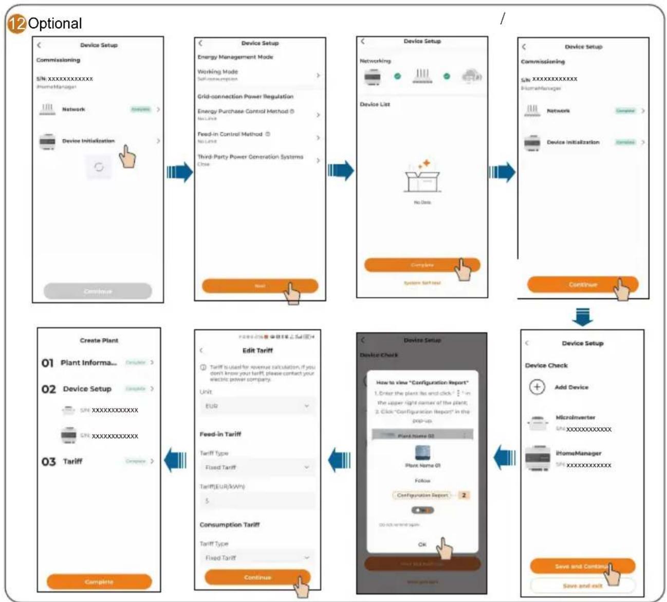
flowchart
graph TD
    A["Device Setup\nCommissioning\nS/N_XXXXXXXXXX\nHomeManager\nNetwork"] --> B["Device Setup\nEnergy Management Mode\nWorking Mode\nSelf-conscription"]
    B --> C["Device Setup\nNetworking\nDevice List\nNo Data\nComplete\nSystem Set Next"]
    C --> D["Device Setup\nCommissioning\nS/N_XXXXXXXXXX\nHomeManager\nNetwork\nDevice Initialization"]
    D --> E["Create Plant\n01 Plant Informa..."]
    E --> F["Edit Tariff\nTariff is used for revenue calculation, if you don't know your tariff, please contact your electric power company\nUnit\nEUR"]
    F --> G["Feed-in Tariff\nTariff Type\nFixed Tariff\nTariff(EUR/kWh)\n$"]
    G --> H["Consumption Tariff\nTariff Type\nFixed Tariff"]
    H --> I["Continue"]
    I --> J["Device Setup\nDevice Check\nHow to view "Configuration Report"\n1. Enter the plant list and click " in the upper right corner of the plant;\n2. Click "Configuration Report" in the pop-up\nPlant Name 02\nPlant Name 01\nFollow\Configuration Report\n2\nOK AND END ON\nOK\nSave and Continue\nSave and exit"]
The plant that has been created will be shown on the "Monitoring" screen. You can tap a plant to check the detailed information about the plant and its devices, as shown in the figure below
![Normal 21°C Ow Real-time Power(W) 0 Installed Power[kWp] 2.00](/content/2026/04/745526/images/2ee5c2972651f87c46102c145f5966c6977e1a0b5c738df5efe7cf054121911c.jpg)
At night, since there is no light, the microinverter in the plant stops working due to the absence of power source. In this case, it does not communicate with the background and its status shows "offline". However, this does not indicate a fault in the device. Once the light conditions return to normal, with stable power source, the microinverter will start up and work again. It will then communicate with the background normally and its status will be "online". If the device stays offline for a long time or in case of other abnormal symptoms, inspect the device and its network connection.
Choose the "Device" tab on the top of the screen to check the devices in the plant and their status.
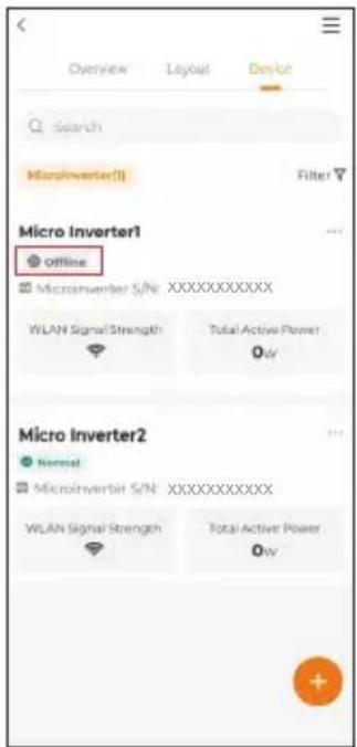
If a microinverter in the list remains offline for an extended period (excluding the situation that the microinverter goes offline at night, which is normal), follow the troubleshooting steps below.
- Check that the home router network is functioning properly.
- Check that the microinverter is using the correct password to connect to the network.
- Determine if the signal is weak because the microinverter is too far from the router. If necessary, add a Wi-Fi extender between the microinverter and the router.
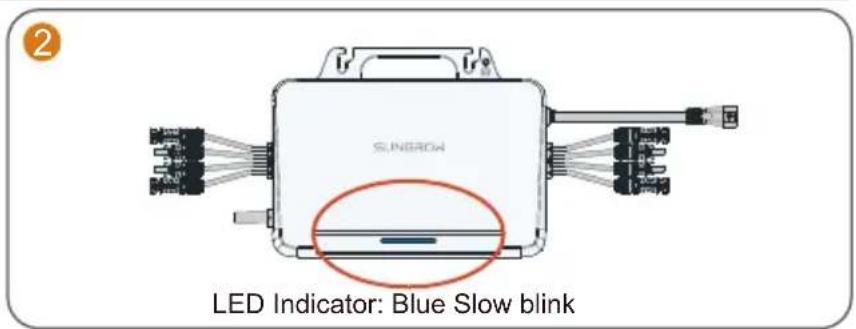
LED Indicator / Voyant DEL / LED-Anzeige / Led-indicator
| Status indicator Color Status | Description | ||
| Blue | Steady on | Running in on-grid state | |
| Blink slow | Standby or starting up | ||
| Red | Steady on | Fault (inverter failure, update failed, etc.) | |
| Blink slow | Updating | ||
| Grey Off | Powered off | ||
If multiple microinverters are used, paste their QR code labels below.

natural_image
Grid of 16 empty gray rectangular boxes with dashed outlines, no text or symbols present
For more product information, visit
http://support.sungrowpower.com/ or scan the QR code
- Quick Installation Guide
- EN
- Safety
- Security Declaration
- DANGER
- Lethal voltage!
- WARNING
- CAUTION
- NOTICE
- MicroInverter
- EU Declaration of Conformity
- Microinverter(WIFI):
- FR
- Tension mortelle !
- GEFAHR
- GEVAAR
- Installation Tool / Werkzeuge zur Installation / Outil d'installation / Montagegereedschap
- Mounting location / Emplacement de montage / Montageort / Montageplaats
- Wiring Steps / Procédure de câblage / Verkabelungsschritte / Bedradingsprocedure
- Commissioning / Mise en service / Inbetriebnahme / Inbedrijfstelling
Brand : Sungrow
Model : S450S
Category : Power inverter