
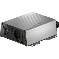
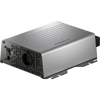
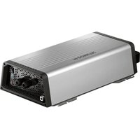
PerfectPower DCC 1224-10 - Battery charger DOMETIC - Free user manual and instructions
Find the device manual for free PerfectPower DCC 1224-10 DOMETIC in PDF.

| Product type | Voltage converter and battery charger |
| Model | PerfectPower DCC 1224-10 |
| Brand | Dometic |
| Conversion | 12 V → 24 V |
| Nominal input voltage | 12 V=== |
| Input voltage range | 8 V - 16 V |
| Charge current | 10 A |
| Charge voltage | 26.4 V - 29.4 V |
| Power | 250 W |
| Output residual ripple | < 50 mV rms |
| Max efficiency | 90 % |
| Standby consumption | < 0.4 A |
| Operating temperature | -20 °C to +50 °C |
| Ambient humidity | ≤ 95 % non-condensing |
| Dimensions (W x D x H) | 153 x 73 x 220 mm |
| Weight | 1.55 kg |
| Protection | Overvoltage, undervoltage, overtemperature, short-circuit, reverse polarity (internal fuse) |
| Compatible battery types | Lead-acid, Gel, AGM, Dometic eStore Lithium |
| Charge characteristic | IU0U (Bulk, Absorption, Float) |
| Settings | DIP switches for voltage, charge mode, eStore mode |
| Optional accessories | Temperature sensor TS-1 |
| Delivery contents | Battery charger, mounting and service instructions |
| Maintenance and cleaning | Clean with a damp cloth, do not immerse in water |
Frequently Asked Questions - PerfectPower DCC 1224-10 DOMETIC
User questions about PerfectPower DCC 1224-10 DOMETIC
0 question about this device. Answer the ones you know or ask your own.
Ask a new question about this device
Download the instructions for your Battery charger in PDF format for free! Find your manual PerfectPower DCC 1224-10 - DOMETIC and take your electronic device back in hand. On this page are published all the documents necessary for the use of your device. PerfectPower DCC 1224-10 by DOMETIC.
USER MANUAL PerfectPower DCC 1224-10 DOMETIC
natural_image
Technical line drawing of an electronic device housing with internal components (no text or symbols)DCC1224-10, DCC1224-20, DCC2412-20, DCC2412-40, DCC2424-40, DCC1212-10, DCC1212-20, DCC1212-40
EN Charger and voltage converter Installation and Operating Manual.....7
natural_image
Technical line drawing of a mechanical assembly with a cylindrical component and mounting base (no text or symbols)
natural_image
Technical line drawing of an electronic device housing with cooling fins and mounting points (no text or symbols)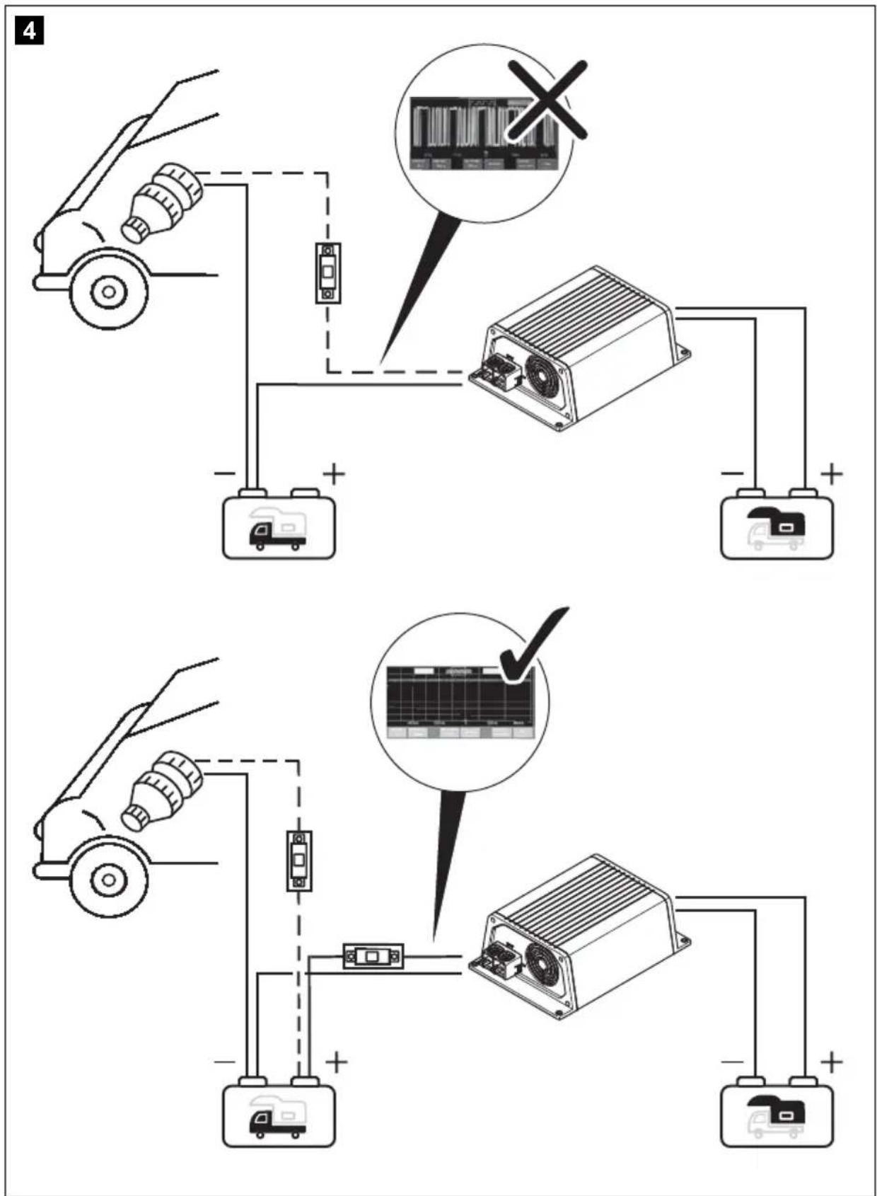
5
6
Please read this instruction manual carefully before installation and first use, and store it in a safe place. If you pass on the product to another person, hand over this instruction manual along with it.
Table of contents
1 Description of symbols....8
2 General safety instructions....8
3 Scope of delivery .....12
4 Accessories....13
5 Target group for this manual....13
6 Intended use ....13
7 Technical description ..... 14
8 Mount charging converter ..... 17
9 Connect charging converter .....18
10 Use charging converter 20
11 Maintaining and cleaning the charging converter.... 22
12 Troubleshooting 23
13 Warranty 23
14 Disposal 23
15 Technical data 24
1 Description of symbols

DANGER!
Safety instruction: Failure to observe this instruction will cause fatal or serious injury.

WARNING!
Safety instruction: Failure to observe this instruction can cause fatal or serious injury.

CAUTION!
Safety instruction: Failure to observe this instruction can lead to injury.

NOTICE!
Failure to observe this instruction can cause material damage and impair the function of the product.

NOTE
Supplementary information for operating the product.
2 General safety instructions
The manufacturer accepts no liability for damage in the following cases:
- Faulty assembly or connection
- Damage to the product resulting from mechanical influences and excess voltage
• Alterations to the product without express permission from the manufacturer - Use for purposes other than those described in the operating manual
For protection, pay close attention to the following basic safety information when using electrical devices:
- Electric shock
- Fire hazards
- Injury
2.1 General safety

DANGER!
- In the event of fire, use a fire extinguisher which is suitable for electrical devices.

WARNING!
- Only use the product as intended.
- Ensure that the red and black terminals never come into contact with each other.
- Disconnect the product from the battery – each time before cleaning and maintenance – before a fuse change (only by specialists)
- if you disassemble the product: - Detach all connections. - Make sure that no voltage is present on any of the inputs and outputs.
- The product may not be used if the product itself or the connection cable are visibly damaged.
- If the power cable for this product is damaged, it must be replaced by the manufacturer, customer service or a similarly qualified person in order to prevent safety hazards.
- This product may only be repaired by qualified personnel. Inadequate repairs may cause serious hazards.
- This product can be used by children aged 8 years or over, as well as by persons with diminished physical, sensory or mental capacities or a lack of experience and knowledge, providing they are supervised or have been taught how to use the product safely and are aware of the resulting risks.
• Electrical devices are not toys.
Always keep and use the product out of the reach of children.
- Children must be supervised to ensure that they do not play with the product.

NOTICE!
- Before start-up, check that the voltage specification on the type plate is the same as that of the power supply.
- Ensure that other objects cannot cause a short circuit to the contacts of the product.
- Store the product in a dry and cool place.
2.2 Safety when installing the product

DANGER!
- Never mount the product in areas where there is a risk of gas or dust explosion.

CAUTION!
- Ensure a secure stand!
The product must be set up and fastened in such a way that it cannot tip over or fall down.

NOTICE!
- Do not expose the product to any heat source (such as direct sunlight or heating). Avoid additional heating of the product.
- Set up the product in a dry location where it is protected against splashing water.
2.3 Safety when connecting the product electronically

DANGER! Danger of fatal electric shock!
- For installation on boats:
If electrical devices are incorrectly installed on boats, this can lead to corrosion damage on the boat. Have the product installed by a qualified (boat) electrician.
- If you are working on electrical systems, ensure that there is somebody close at hand who can help you in emergencies.

WARNING!
- Make sure that the lead has a sufficient cross-section.
- Lay the cables so that they cannot be damaged by the doors or the bonnet.
Crushed cables can lead to serious injury.

CAUTION!
- Lay the cables so that they cannot be tripped over or damaged.

NOTICE!
- Use ductwork or cable ducts if it is necessary to lay cables through metal panels or other panels with sharp edges.
- Do not lay the AC cable and DC cable in the same conduit (empty pipe).
- Do not lay the cables so that they are loose or heavily kinked.
- Firmly secure the cables.
- Do not pull on the cables.
2.4 Safety when operating the product

WARNING!
- If the product is used in facilities with open lead acid batteries, the room must be well ventilated. These batteries give off explosive hydrogen gas that can be ignited by sparks on electrical connections.

CAUTION!
• D o not operate the product
– In salty, wet or damp environments
– In the vicinity of corrosive fumes
– In the vicinity of combustible materials
– In areas where there is a danger of explosions
- Before activating, ensure that the power supply line and plug are dry.
• Always disconnect the power supply when working on the product. - Please be aware that parts of the product may still produce voltage even after activation of the safety guard (fuse).
- Do not disconnect any cables when the product is still in use.

NOTICE!
- Make sure the air inlets and outlets of the product are not covered.
- Ensure good ventilation.
2.5 Safety precautions when handling batteries

WARNING!
- Batteries may contain aggressive and corrosive acids. Avoid battery fluid coming into contact with your body. If your skin does come into contact with battery fluid, thoroughly wash the part of your body in question with water. If you sustain any injuries from acids, contact a doctor immediately.

CAUTION!
- When working on batteries, do not wear any metal objects such as watches or rings. Lead acid batteries can cause short circuits which can cause serious injuries.
• Danger of explosions!
Never attempt to charge a frozen or defective battery. In this case place the battery in a frost-free area and wait until the battery has adjusted to the ambient temperature. Then start the charging process.
- Wear goggles and protective clothing when you work on batteries. Do not touch your eyes when you working on batteries.
- Do not smoke and ensure that no sparks can arise in the vicinity of the engine or battery.

NOTICE!
- Only use rechargeable batteries.
- Use sufficient cable cross sections.
- Protect the positive conduit with a fuse.
- Prevent any metal parts from falling on the battery. This can cause sparks or short circuit the battery and other electrical parts.
- Make sure the polarity is correct when connecting.
- Follow the instructions of the battery manufacturer and those of the manufacturer of the system or vehicle in which the battery is used.
- If you need to remove the battery, disconnect it first from the ground connection. Disconnect all connections and all consumers from the battery before removing it.
3 S c o p e o f d
Description
1 Battery charger
- Installation and operating manual
4 A c c e s s o r i
Available as accessories (not included in the scope of delivery):
Description Ref. no.
Temperature sensor TS-1 9600000099
5 Target group for this manual
The chapter "Connect charging converter" on page 18 chapter is solely intended for qualified professionals who are familiar with the relevant VDE regulations.
All other chapters are intended for the users.
6 Intended use
The PerfectCharge DCC battery chargers can charge batteries used on board vehicles or boats while driving, or supply them with a maintenance voltage for power generation. Additionally, the devices can be used as a stable power supply.
The DCC battery chargers are used for continuous charging of supply or on-board batteries (body batteries):
- 12 V---Charge converter: DCC1212-10, DCC1212-20, DCC1212-40
• 12 V==Voltage converter: DCC2412-20, DCC2412-40
• 24 V== Charging converter: DCC2424-40
• 24 V=Voltage converter: DCC1224-10, DCC1224-20
The DCC battery chargers are used to charge the following battery types:
- Lead acid batteries
- Lead gel batteries
- Fleece batteries (AGM batteries)
• Dometic eStore lithium batteries

NOTICE!
Check the charging requirements from the battery manufacturer before charging your battery.
Do not use the device under any circumstances to charge other types of batteries (ex. NiCd, NiMH, etc.).

WARNING! Danger of explosions!
- Do not charge batteries with a cell conclusion. The oxyhydrogen they produce can cause explosions.
- Do not charge lead acid batteries in unventilated rooms. The oxyhydrogen they produce can cause explosions.
- Do not charge NiCd batteries or non-rechargeable batteries with this device. The sleeves of these batteries can explode.
7 Technical description
Because of its low weight and compact design, the charging converter can easily be installed in RVs, commercial vehicles or motor and sailing yachts. While driving it charges batteries that are used on board vehicles or boats to generate power or supplies them with a retention voltage so that they do not unload.
The 12 V--- or 24 V--- voltage from a vehicle or boat battery is transformed into a stable 12 V--- or 24 V--- DC voltage.
The isolation of the input and output voltages means the output voltage can be kept stable without interference from the input circuit.
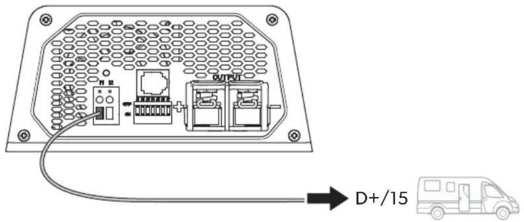
The charging converter is switched on via a 12/24 V signal:
• D + signal
• alternator signal (terminal 15)
- a switched input signal

NOTICE!
When terminal 15 is used, the starter battery may discharge even when the engine is off, if the ignition is set to "ON".
The battery charger has various protective mechanisms:
- High voltage shutdown: The battery charger shuts itself off when the voltage exceeds the cut-off value. It restarts when the voltage returns to the restart value.
- Low voltage shutdown: The battery charger shuts itself off when the voltage sinks below the cut-off value. It restarts when the voltage rises to the restart value.
- High temperature shutdown: The battery charger switches off when the temperature inside the device exceeds a cut-off value. It restarts when the voltage rises to the restart value.
- Protection against short circuit: The LED on the battery charger signals a malfunction if a short circuit has been generated. The device fuse must be replaced by a professional after it has been triggered by excess current.

NOTE
The individual values are found in chapter "Protective devices" on page 27.
The battery charger can be adapted to different battery types via DIP switches.
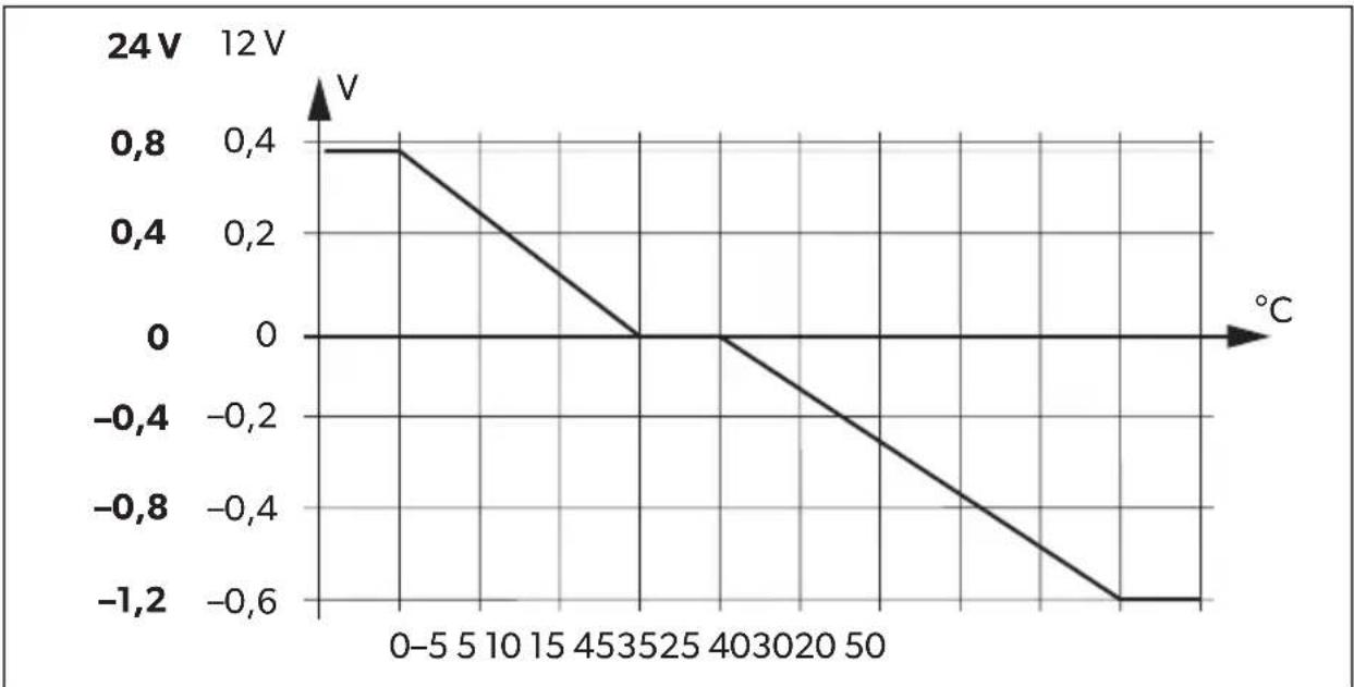
When a TS-1 temperature sensor is connected, the charging converter adjusts the charging voltage according to the measured temperature, see chapter "Technical data" on page 24.
7.1 Connections and controls
Item in
fig. 1,
page 3
Description
1 Input terminals (+) of starter battery
2 Input terminals (−) of starter battery
3 Control cable (I1) for turning on the vehicle with on-board voltage (D+ or terminal 15 (ignition))
4 LED display
5 Power regulation (I2) to limit the charging current to 5 A
6 RJ11 terminal: Connection of a temperature sensor (accessory)
7 Dip switch, see chapter "Adjust charging converter" on page 20
8 Output terminals (+) to the body battery
9 Output terminals (−) to the body battery
7.2 Battery charging function
The charging characteristics are referred to as IUOU characteristics.
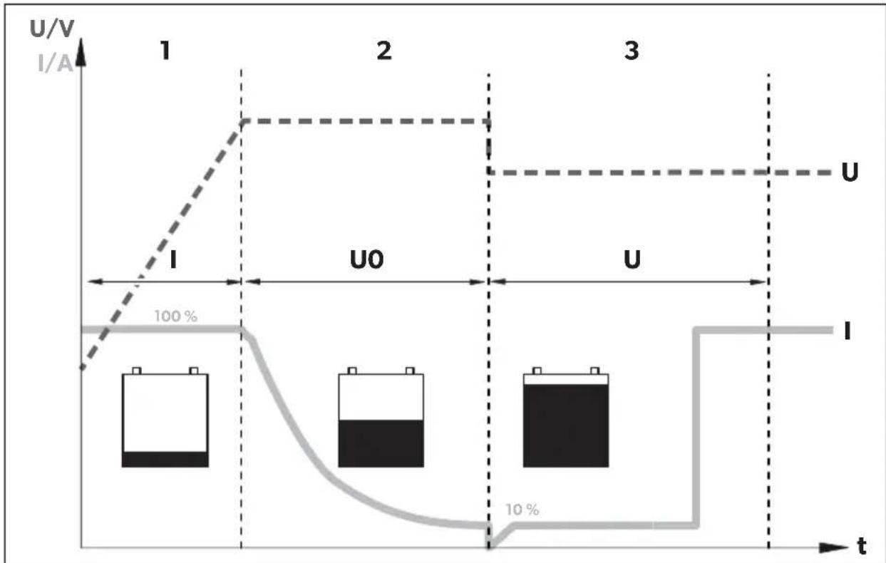
line
| t | U/V (I/A) | Current (I/A) | |---|---|---| | 1 | High | Low | | 2 | High | Low | | 3 | Low | 10% |1: I phase (bulk)
At the beginning of the charging process, the flat battery is charged with a constant current (100 % charge current) until the battery voltage reaches the charging end voltage. The charging current decreases when the battery has reached this charging level.
2: U0 phase (absorption)
Now the absorption charging process (U0 phase) begins, where the duration depends on the battery. The voltage remains constant (U0).
This phase is limited to maximal 3 hours to prevent overcharging the battery while driving.
3: U phase (float)
After the U0 phase, the battery charger switches to conservation charging function (U phase).
8 M o u n t c h a
8.1 Tools required
For the electrical connection you will need the following tools:
- Crimping tool
- 4 flexible connection cables: + and – for the starter battery, + and – for the body battery. 1 flexible signal cable for connection to D+ or the ignition. The required cross-section can be found in the table chapter “Connect charging converter” on page 19.
- Cable lugs and conductor sleeves
For fastening the battery charger you will need the following tools:
• Machine bolts (M4) with washers and self-locking nuts or
- self-tapping screws or wood screws.
8.2 Installation instructions
When selecting the installation location, pay attention to the following instructions:
- The battery charger can be installed horizontally as well as vertically.
- The battery charger must be installed in a place that is protected from moisture.
- The battery charger may not be installed in the presence of flammable materials.
- The battery charger may not be installed in a dusty environment.
- The place of installation must be well ventilated. A ventilation system must be available for installations in small, enclosed spaces. The minimum clearance around the battery charger must be at least 5 cm (fig. 2, page 4).
- The battery charger air inlet and air outlet must remain free.
- At ambient temperatures higher than 40^ (ex. in engine or boiler rooms, direct sunlight), the battery charger may switch off, although the power of the connected loads is below the rated load (derating).
- The device must be installed on a level and sufficiently sturdy surface.
8.3 Charging converter

NOTICE!
Before drilling any holes, make sure that no electrical cables or other parts of the vehicle can be damaged by drilling, sawing and filing.
▶ Pay attention to the distance specifications (fig. 2, page 4).
▶ Mount the charging converter as shown (fig. 3, page 4).
9 Connect charging converter

WARNING!
Do not reverse the polarity. Reverse polarity of the battery connections can cause injury and damage the device.

CAUTION!
- Avoid coming into contact with the battery fluid under any circumstances.
- Batteries with a cell short circuit may not be charged as explosive gases may form due to overheating of the battery.

NOTICE!
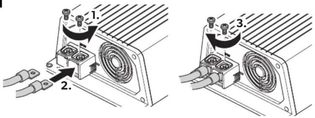
Tighten the nuts and bolts with a maximum torque of 12–13 Nm. Loose connections may cause overheating.
Observe the following instructions when connecting the battery:
- Make sure the battery poles are clean when connecting the terminals.
- Make sure the plug connector is fitted securely.
- Select a sufficient cross-section for the connection cable.
- Lay the cables in accordance with VDE 100 (Germany).
-
Connect the negative cable directly to the negative terminal of the battery, and not to the chassis of a vehicle or boat.
-
Use the following cable colors:
- Red: positive connection
- Black: negative connection
Determine cable cross-section

NOTE
Keep the distance to the body battery as short as possible.
The minimum cable cross-section depends on the maximum cable length:
| Cable length Minimum cable cross-section/Fuse | |||||
| 2.5 mm ^2 /30 A | 4 mm ^2 /40 A | 6 mm ^2 /60 A | 10 mm ^2 /80 A | ||
| DCCxxxx-10 | to the starter battery | ≤7 m | ≤11 m | ≤16 m | - |
| to battery structure | ≤2 m | ≤3.5 m | ≤5 m | - | |
| DCC xxxx-20 | to the starter battery | - | ≤5.5 m | ≤8 m | ≤14 m |
| to battery structure | - | ≤1.5 m | ≤2.5 m | ≤4 m | |
| DCCxxxx-40 | to the starter battery | - | - | - | ≤7 m |
| to battery structure | - | - | - | ≤2 m | |
9.1 Connect charging converter

NOTICE!
The charging converter must not be connected directly to the alternator.
▶ Connect the charging converter as shown:
- Correct connection diagram: fig. 4, page 5
- Connecting the batteries: fig. 5, page 6
- Connect control line (11): fig. 6, page 6
9.2 Connect accessories

NOTE - Performance regulation
To limit the output current of the charging converter to 5 A, a positive control signal must be present at contact "12" (fig. 1 5, page 3).
▶ Connect the accessory to the following contacts:
– Performance regulation (I2): fig. 1 5, page 3
- Temperature sensor: fig. 1 6, page 3
10 Use charging converter
10.1 Switch charging converter on/off
The charging converter turns on automatically as soon as it receives a positive control signal. The status LED glows blue.
The charging converter switches off automatically when the control signal is no longer present.

NOTE
If the control signal of the charging converter is switched via the ignition, the starter battery can discharge if the engine is not started in a timely manner.
10.2 Adjust charging converter

NOTE
Take the values for the charging end voltage and maintenance charge voltage of your battery from the battery manufacturer's specifications.
You can adjust the device using the DIP switch (fig. 1 7, page 3).
Set switchover voltage/constant voltage
You can use the DIP switches S1 and S2 to set the value of the end-of-charge voltage.
| S1 S2 | Switchover voltage/constant voltage | |||
| 12 V 24 V | ||||
| ON | ON | 14.4 | V | 28 |
| OFF ON 14.1 V | 28.2 V | |||
| ON OFF | 14.7 | V | 29.4 | |
| OFF | OFF | |||
Set float voltage
You can use the DIP switches S3 and S4 to set the float voltage in the U phase (float).
| S3 S4 | Float voltage | ||
| 12 V 24 V | |||
| ON | ON | 13.8 | V |
| OFF ON 13.5 V 27.0 V | |||
| ON OFF | 13.2 | V | |
| OFF OFF | |||
2:
Set charging mode

WARNING! Danger of explosions!
Use only the charging mode appropriate for your battery type. If necessary inquire at a specialist workshop.
You can set the charger mode using the S5 and S6 DIP switches.
| S5 S6 Charger Mode | |
| ON ON IU0U- charging | Refer to chapter “Battery charging function” on page 16. |
| OFF ON Constant voltage 1 | The battery charger works as a constant voltage source, where the value of the voltage corresponds to the set charging end voltage. |
| ON OFF Constant voltage 2 | The battery charger works as a constant voltage source, with the value of the voltage corresponding to the set floating voltage. |
| OFF OFF | |
Set eStore mode (DCC1212-40 only and DCC2412-40 with optional eStore battery)
You can set the eStore charging mode using the S7 DIP switch.
S7 eStore charging characteristic
ON OFF
OFF ON
For the eStore charging characteristic, a temperature sensor must be connected.

NOTE
When used without a temperature sensor, the eStore charging mode is constant at 13.8 V with a maximum of 35 A.
The eStore charging mode has the following charging characteristics:
Output voltage
(Charging end voltage): 13.8 V=
Output current
(Charging current):
< -10^ O A
11 Maintaining and cleaning the charging converter

NOTICE! Risk of damage to the device!
Never clean the device under running water or in dish water.
Do not use abrasive cleaning agents or hard objects during cleaning as these can damage the appliance.
▶ Occasionally clean the device with a damp cloth.
12 Troubleshooting

WARNING!
Do not open the device. You risk exposing yourself to an electric shock by doing this.

NOTE
If you have detailed questions about the battery charger data, please contact the manufacturer (addresses on the back of the instruction manual).
LED does not glow
▶ Check the electric connections.
If you cannot find an error, contact customer service.
13 Warranty
The statutory warranty period applies. If the product is defective, please contact the manufacturer's branch in your country (see the back of the instruction manual for the addresses) or your retailer.
For repair and guarantee processing, please include the following documents when you send in the device:
• A copy of the receipt with purchasing date
- A reason for the claim or description of the fault
14 Disposal
▶ Place the packaging material in the appropriate recycling waste bins wherever possible.
If you wish to finally dispose of the product, ask your local recycling centre or specialist dealer for details about how to do this in accordance with the applicable disposal regulations.
15 Technical data
| DCC1224-10 DCC1224-20 | ||
| Ref. no.: 9600003748 9600003749 | ||
| Transformation: | 12 V → 24 V | |
| Nominal input voltage: 12 V--- | ||
| Input voltage range: 8 V - 16 V | ||
| Charging current: 10 A 20 A | ||
| Charging voltage: 26.4 V - 29.4 V | ||
| Output: 250 W | 500 W | |
| Residual ripple of output voltage at rated current: | < 50 mV rms | |
| Efficiency: | up to 90 % | |
| Idle power consumption: | < 0.4 A | |
| Ambient temperature for operation: | -20 °C to +50 °C | |
| Ambient humidity: | ≤ 95 % Non-condensing | |
| Dimensions (W x D x H): | 153 x 73 x 220 mm | 153 x 73 x 260 mm |
| Weight: | 1.55 kg | 1.85 kg |
| Inspection/certification: |  | |
| DCC2412-20 DCC2 | 412-40 | |
| Ref. no.: 9600003750 9600003 | 751 | |
| Transformation: | 24 V → 12 V | |
| Nominal input voltage: 24 V== | ||
| Input voltage range: 16 V - 32 V | ||
| Charging current: 20 A 40 A | ||
| Charging voltage: 13.2 V - 14.7 V | ||
| Output: 250 W 500 W | ||
| Residual ripple of output voltage at rated current: | < 100 mVeff | |
| Efficiency up to: 90 % | ||
| Idle power consumption: | < 0.4 A | |
| Ambient temperature for operation: | -20 °C to +50 °C | |
| Ambient humidity: | ≤ 95 % Non-condensing | |
| Dimensions (W x D x H): | 153 x 73 x 220 mm | 153 x 73 x 260 mm |
| Weight: | 1.55 kg | 1.85 kg |
| Inspection/certification: |  DCC2424-10 DCC1212-10 DCC2424-10 DCC1212-10 | |
| Ref. no.: 9600003752 9600003753 | ||
| Transformation: | 24 V → 24 V | 12 V → 12 V |
| Nominal input voltage: | 24 V--- | 12 V--- |
| Input voltage range: | 16 V - 32 V | 8 V - 16 V |
| Charging current: 10 A | ||
| Charging voltage: | 26.4 V - 29.4 V | 13.2 V - 14.7 V |
| Output: | 250 W | 120 W |
| Residual ripple of output voltage at rated current: | < 100mVeff | < 50 mVeff |
| Efficiency up to: | 90 % | |
| Idle power consumption: | < 0.4 A | |
| Ambient temperature for operation: | -20 °C to +50 °C | |
| Ambient humidity: | ≤ 95 % Non-condensing | |
| Dimensions (W x D x H): | 153 x 73 x 220 mm | 153 x 73 x 180 mm |
| Weight: | 1.55 kg | 1.25 kg |
| Inspection/certification: |  DCC1212-20 DCC1212-40 DCC1212-20 DCC1212-40 | |
| Ref. no.: 9600003754 9600003755 | ||
| Transformation: | 12 V→12 V | |
| Nominal input voltage: 12 V--- | ||
| Input voltage range: 8 V - 16 V | ||
| Charging current: 20 A 40 A | ||
| Charging voltage: 13.2 V - 14.7 V | ||
| Output: 250 W 500 W | ||
| Residual ripple of output voltage at rated current: | < 50 mVeff | |
| Efficiency up to: 90 % | ||
| Idle power consumption: | < 0.4 A | |
| Ambient temperature for operation: | -20 °C to +50 °C | |
| Ambient humidity: | ≤ 95 % Non-condensing | |
| Dimensions (W x D x H): | 153 x 73 x 220 mm | 153 x 73 x 260 mm |
| Weight: | 1.55 kg | 1.85 kg |
| Inspection/certification: |  | |
Protective devices
| 12 V | 24 V | |
| Input: | High voltage, low voltage, reverse polarity protection (internal fuse) | |
| Low-voltage cut-out: | 8 V | 16 V |
| Low voltage restart: | 10 V | 20 V |
| High voltage shutdown: | 16 V | 32 V |
| High voltage restart: | 15.5 V | 31 V |
| Temperature: | Shutdown | |
| Short circuit protection: | yes, I_pk | |
Temperature compensation

NOTE
The temperature compensation is only effective if a TS-1 temperature sensor is connected and the IUOU charging mode is selected.
line
| Temperature (°C) | Voltage (V) | | ---------------- | ----------- | | 0 | 0.8 | | 5 | 0.4 | | 10 | 0.0 | | 15 | -0.4 | | 20 | -0.8 | | 25 | -1.2 | | 30 | -1.6 | | 35 | -2.0 | | 40 | -2.4 | | 45 | -2.8 | | 50 | -3.2 |line
| t | U/V (I/A) | Current (I/A) | |---|---|---| | 1 | High | Low | | 2 | High | Low | | 3 | Low | 10% |1: I-Phase (Bulk)
7 Description technique
2: Phase U0 (absorption)
line
| °C | 24V | | --- | --- | | -5 | 0.8 | | 0 | 0.8 | | 15 | 0 | | 20 | 0 | | 45 | -1.2 | | 50 | -1.2 |2: fase U0 (absorption)
line
| °C | 24V | | --- | --- | | -5 | 0.8 | | 0 | 0.8 | | 15 | 0 | | 20 | 0 | | 45 | -1.2 | | 50 | -1.2 |line
| t | U/V (I/A) | Current (I/A) | |---|---|---| | 1 | High | Low | | 2 | High | Low | | 3 | Low | 10% |1: fase I (bulk)
2: fase U0 (absorption)
WAARSCHUWING! Explosiegevaar!
line
| t | U/V (I/A) | | --- | --------- | | 1 | 100% | | 2 | U0 | | 3 | U |1: I-fase (bulk)
WAARSCHUWING! Explosiegevaar!
line
| t | U/V (I/A) | Current (I/A) | |---|---|---| | 1 | High | Low | | 2 | High | Low | | 3 | Low | 10% |1: I-fase (Bulk)
2: U0-fase (Absorption)
line
| t | U/V (I/A) | | --- | --------- | | 1 | 100% | | 2 | U0 | | 3 | I |1: I-fas (bulk)
2: U0-fas (absorption)
line
| t | U/V (I/A) | |---|---| | 1 | 100% | | 2 | U0 | | 3 | U |1: I-fase (bulk)
I starten av ladingen lades det tomme batteriet med konstant strøm (100 % ladestrøm) til batterispenningen när lade-sluttspenningen. Hvis batteriet när dette spenningsnivået, avtar ladestrømmen.
line
| t | U/V (I/A) | | --- | --------- | | 1 | 100% | | 2 | U0 | | 3 | U |1: I-vaihe (Bulk)
line
| t | U/V (I/A) | Current (I/A) | |---|---|---| | 1 | High | Low | | 2 | High | Low | | 3 | Low | 10% |line
| °C | 24V | | --- | --- | | -5 | 0.8 | | 0 | 0.8 | | 15 | 0 | | 20 | 0 | | 45 | -1.2 | | 50 | -1.2 |line
| t | U/V (I/A) | Current (I/A) | |---|---|---| | 1 | High | Low | | 2 | High | Low | | 3 | Low | 10% |1: Faza I (Bulk)
2: Faza UO (Absorption)
line
| °C | V | | --- | ------- | | -5 | 0.8 | | 0 | 0.8 | | 15 | 0 | | 20 | 0 | | 45 | -1.2 | | 50 | -1.2 |line
| t | U/V (I/A) | | --- | --------- | | 1 | 100% | | 2 | U0 | | 3 | U |1: I fáza (celok)
line
| t | U/V (I/A) | Current (I/A) | |---|---|---| | 1 | High | Low | | 2 | High | Low | | 3 | Low | 10% |1: Fáze I (Bulk)
line
| t | U/V (I/A) | | --- | --------- | | 1 | 100% | | 2 | U0 | | 3 | U |1: I-fázis (töltés)
line
| °C | 24V | | --- | --- | | -5 | 0.8 | | 0 | 0.8 | | 15 | 0 | | 20 | 0 | | 45 | -1.2 | | 50 | -1.2 |AUSTRALIA
Dometic Australia Pty. Ltd.
1 John Duncan Court
Varsity Lakes QLD 4227
1800 212121
+61 7 55076001
Mail: sales@dometic.com.au
AUSTRIA
Dometic Austria GmbH
Neudorferstraße 108
A-2353 Guntramsdorf
+43 2236 908070
+43 2236 90807060
Mail: info@dometic.at
BENELUX
Dometic Branch Office Belgium
Lourdesstraat 84
B-8940 Geluwe
+32 2 3598040
+32 2 3598050
Mail: info@dometic.be
BRAZIL
Dometic DO Brasil LTDA
Avenida Paulista 1754, conj. 111
SP 01310-920 Sao Paulo
+551132513352
+551132513362
Dometic Group Asia Pacific
Suites 2207-11 · 22/F · Tower 1
The Gateway · 25 Canton Road,
Tsim Sha Tsui · Kowloon
+852 2 4611386
+852 2 4665553
Mail: info@waeco.com.hk
HUNGARY
Dometic Zrt. Sales Office
Kerékgyártó u. 5.
H-1147 Budapest
+3614684400
+3614684401
Dometic Italy S.r.l.
Via Virgilio, 3
I-47122 Forlì (FC)
+39 0543 754901
+39 0543 754983
Mail: vendite@dometic.it
JAPAN
Dometic KK
Maekawa-Shibaura, Bldg. 2
2-13-9 Shibaura Minato-ku
Tokyo 108-0023
+81 3 5445 3333
+81354453339
Mail: info@dometic.jp
MEXICO
Circuito Médicos No. 6 Local 1
Colonia Ciudad Satélite
CP 53100 Naucalpan de Juárez
Estado de México
+52 55 5374 4108
+52 55 5393 4683
Mail: info@dometic.com.mx
NETHERLANDS
Dometic Benelux B.V.
Ecustraat 3
NL-4879 NP Etten-Leur
+31 76 5029000
+31 76 5029019
Mail: info@dometic.nl
NEW ZEALAND
Dometic New Zealand Ltd.
PO Box 12011
Penrose
Auckland 1642
+6496221490
+6496221573
Mail: customerservices@dometic.co.nz
NORWAY
Dometic Norway AS
∅sterøyveien 46
N-3232 Sandefjord
+47 33428450
+47 33428459
Mail: firmapost@dometic.no
POLAND
Dometic Poland Sp. z o.o.
Ul. Puławska 435A
PL-02-801 Warszawa
+48 22 414 3200
+48 22 414 3201
Mail: info@dometic.pl
PORTUGAL
Dometic Spain, S.L.
Komsomolskaya square 6-1
RU-107140 Moscow
+7 495 780 79 39
+7 495 916 56 53
Mail: info@dometic.ru
SINGAPORE
Dometic Pte Ltd
18 Boon Lay Way
06-141 Trade Hub 21
Singapore 609966
+65 6795 3177
+65 6862 6620
Mail: dometic@dometic.com.sg
SLOVAKIA
Dometic Slovakia s.r.o.
Sales Office Bratislava
Nádražná 34/A
900 28 Ivánka pri Dunaji
/ +421 2 45 529 680
Mail: bratislava@dometic.com
SOUTH AFRICA
Dometic (Pty) Ltd.
Regional Office
South Africa & Sub-Saharan Africa
2 Avalon Road
West Lake View Ext 11
Modderfontein 1645
Johannesburg
+27 87 3530380
Mail: info@dometic.co.za
SPAIN
Dometic Spain S.L.
Avda. Sierra del Guadarrama, 16
E-28691 Villanueva de la Cañada
Madrid
+34 91 833 60 89
+34 900 100 245
Mail: info@dometic.es
SWEDEN
Dometic Scandinavia AB
Gustaf Melins gata 7
Dometic Switzerland AG
Riedackerstrasse 7a
CH-8153 Rümlang
+41 44 8187171
+41 44 8187191
Mail: info@dometic.ch
UNITED ARAB EMIRATES
Dometic Middle East FZCO
P.O.Box17860
S-D 6, Jebel Ali Freezone
Dubai
+97148833858
+97148833868
Mail: info@dometic.ae
UNITED KINGDOM
Dometic UK Ltd.
Dometic House, The Brewery
Blandford St. Mary
Dorset DT11 9LS
+44 344 626 0133
+44 344 626 0143
Mail: customerservices@dometic.co.uk
USA
Dometic RV Division
1120 North Main Street
Elkhart, IN 46515
+1574-264-2131
- Table of contents
- Description of symbols
- DANGER!
- WARNING!
- CAUTION!
- NOTICE!
- NOTE
- General safety instructions
- General safety
- Safety when installing the product
- Safety when connecting the product electronically
- DANGER! Danger of fatal electric shock!
- - For installation on boats:
- Safety when operating the product
- Safety precautions when handling batteries
- • Danger of explosions!
- S c o p e o f d
- Description
- A c c e s s o r i
- Target group for this manual
- Intended use
- WARNING! Danger of explosions!
- Technical description
- Connections and controls
- Battery charging function
- 1: I phase (bulk)
- 2: U0 phase (absorption)
- 3: U phase (float)
- M o u n t c h a
- Tools required
- Installation instructions
- Charging converter
- Connect charging converter
- Determine cable cross-section
- Connect charging converter
- Connect accessories
- NOTE - Performance regulation
- Use charging converter
- Switch charging converter on/off
- Adjust charging converter
- Set switchover voltage/constant voltage
- Set float voltage
- Set charging mode
- Set eStore mode (DCC1212-40 only and DCC2412-40 with optional eStore battery)
- S7 eStore charging characteristic
- Maintaining and cleaning the charging converter
- NOTICE! Risk of damage to the device!
- Troubleshooting
- LED does not glow
- Warranty
- Disposal
- Temperature compensation
- 1: I-Phase (Bulk)
- Description technique
- 2: Phase U0 (absorption)
- 2: fase U0 (absorption)
- 1: fase I (bulk)
- WAARSCHUWING! Explosiegevaar!
- 1: I-fase (bulk)
- 2: U0-fase (Absorption)
- 1: I-fas (bulk)
- 2: U0-fas (absorption)
- 1: I-vaihe (Bulk)
- 1: Faza I (Bulk)
- 2: Faza UO (Absorption)
- 1: I fáza (celok)
- 1: Fáze I (Bulk)
- 1: I-fázis (töltés)
- AUSTRALIA
- Dometic Australia Pty. Ltd.
- AUSTRIA
- Dometic Austria GmbH
- BENELUX
- Dometic Branch Office Belgium
- BRAZIL
- Dometic DO Brasil LTDA
- Dometic Group Asia Pacific
- HUNGARY
- Dometic Zrt. Sales Office
- Dometic Italy S.r.l.
- JAPAN
- Dometic KK
- MEXICO
- NETHERLANDS
- Dometic Benelux B.V.
- NEW ZEALAND
- Dometic New Zealand Ltd.
- NORWAY
- Dometic Norway AS
- POLAND
- Dometic Poland Sp. z o.o.
- PORTUGAL
- Dometic Spain, S.L.
- SINGAPORE
- Dometic Pte Ltd
- SLOVAKIA
- Dometic Slovakia s.r.o.
- SOUTH AFRICA
- Dometic (Pty) Ltd.
- SPAIN
- Dometic Spain S.L.
- SWEDEN
- Dometic Scandinavia AB
- Dometic Switzerland AG
- UNITED ARAB EMIRATES
- Dometic Middle East FZCO
- UNITED KINGDOM
- Dometic UK Ltd.
- USA
- Dometic RV Division
Brand : DOMETIC
Model : PerfectPower DCC 1224-10
Category : Battery charger