
PerfectView BVS 71000 - LCD Screen DOMETIC - Free user manual and instructions
Find the device manual for free PerfectView BVS 71000 DOMETIC in PDF.



| Product type | TFT color LCD screen for vehicle |
| Models | PerfectView BVS 71000 (M55LX AHD: 5", M75LX AHD: 7") |
| Screen size | 5" (12.7 cm) or 7" (17.8 cm) depending on model |
| Resolution | 384,000 pixels (5") or >600,000 pixels (7") |
| Brightness | 350 cd/m² (5") or 800 cd/m² (7") |
| TV standards | 1080p30/25, 720p30/25, PAL, NTSC (auto) |
| Supply voltage | 12 - 30 V= |
| Max power | 10 W |
| Operating temperature | -20 °C to 70 °C |
| Storage temperature | -30 °C to 70 °C |
| Max humidity | 85% |
| Vibration resistance | 6 g |
| Dimensions (WxHxD) | 146 x 87 x 26 mm (5") or 190 x 110 x 26 mm (7") |
| Weight | 350 g (5") or 400 g (7") |
| Main functions | 4 camera inputs, manual/auto switching, adjustable distance markings, adaptive backlight, multilingual menu |
| Maintenance and cleaning | Clean with a damp cloth; do not use hard or sharp objects |
| Safety | Do not mount in airbag zone, secure mounting, do not use with wet hands, do not immerse |
| Spare parts | Sun visors available (5" : 9102200200, 7" : 9102200201) |
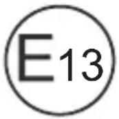
| Certification | E13 |
| Usage | Professional, in all vehicles (reversing, surveillance) |
Frequently Asked Questions - PerfectView BVS 71000 DOMETIC
User questions about PerfectView BVS 71000 DOMETIC
0 question about this device. Answer the ones you know or ask your own.
Ask a new question about this device
Download the instructions for your LCD Screen in PDF format for free! Find your manual PerfectView BVS 71000 - DOMETIC and take your electronic device back in hand. On this page are published all the documents necessary for the use of your device. PerfectView BVS 71000 by DOMETIC.
USER MANUAL PerfectView BVS 71000 DOMETIC
Please read this instruction manual carefully before installation and first use, and store it in a safe place. If you pass on the product to another person, hand over this instruction manual along with it.
Table of contents
1 Explanation of symbols. 9 2 Safety and installation instructions 10 3 Scope of delivery 12 4 Accessories. 12 5 Intended use 13 6 Technical description 13 7 Installing the LCD monitor 15 8 Using the LCD monitor. 18 9 Cleaning and caring for the LCD monitor 21 10 Warranty 21 11 Disposal. 21 12 Technical data 21
1 Explanation of symbols

CAUTION!
Safety instruction: Indicates a hazardous situation that, if not avoided, could result in minor or moderate injury.

NOTICE!
Indicates a situation that, if not avoided, can result in property damage.

NOTE
Supplementary information for operating the product.
2 Safety and installation instructions
Please observe the safety instructions and stipulations issued by the vehicle manufacturer and service workshops.
The manufacturer accepts no liability for damage in the following cases:
- Faulty assembly or connection
- Damage to the product resulting from mechanical influences and incorrect connection voltage
- Alterations to the product without express permission from the manufacturer
- Use for purposes other than those described in the operating manual

NOTICE! Beware of damage
- To prevent the risk of short circuits, always disconnect the negative terminal of the vehicle's electrical system before working on it. If the vehicle has an additional battery, its negative terminal should also be disconnected.
- Inadequate supply cable connections could result in short circuits, causing:
- Cable fires
- The airbag being triggered
- Damage to electronic control equipment
- Electrical malfunctions (indicators, brake light, horn, ignition, lights)
Therefore, please observe the following instructions:
- When working on the following cables, only use insulated cable terminals, plugs and flat sockets:
- 30 (direct supply from positive battery terminal)
- 15 (connected positive terminal, behind the battery)
- 31 (return cable from the battery, earth)
- 58 (reversing light)
Do not use porcelain wire connectors.
- Use a crimping tool (fig. 1 12, page 3) to connect the cables.
- Screw the cable when connecting cable 31 (earth)
- Screw on the cable using a cable terminal and serrated washer to one of the vehicle's earth bolts or
- Screw the cable to the bodywork using a cable terminal and a self-tapping screw
Make sure there is a good earth connection.
If you disconnect the negative terminal of the battery, all data stored in the volatile memories will be lost.
- The following data must be reset, depending on the vehicle equipment options:
- Radio code
- Vehicle clock
- Timer
- On-board computer
- Seat position
You can find instructions for making these settings in the operating manual.
Observe the following installation instructions:

CAUTION!
- Secure the monitor in such a way that it cannot become loose under any circumstances (sudden braking, accidents) and cause injuries to the occupants of the vehicle.
- Do not attach the monitor in the air bag deployment path, as this could cause injury if the airbags are triggered.
Observe the following instructions when working with electrical parts:
- When testing the voltage in electrical cables, only use a diode test lamp (fig. 1 1, page 3) or a voltmeter (fig. 2, page 3). Test lamps with a bulb (fig. 1 3, page 3) consume voltages which are too high and can damage the vehicle's electronic system.
- When routing the electrical connections, ensure that:
- They are not kinked or twisted
- They do not rub on edges
- They are not laid in sharp-edged ducts without protection (fig. 3, page 4).
Insulate all connections. - Secure the cables against mechanical wear by using cable binders or insulating tape, for example on existing cables.
Observe the following instructions when handling the LCD monitor:

CAUTION!
- People (including children) whose physical, sensory or mental capacities or whose lack of experience or knowledge prevent them from using this product safely should not use it without the supervision or instruction of a responsible person.
- Do not open the monitor (fig. 4, page 4).
- Do not submerge the monitor in water (fig. 5, page 4); the monitor is not waterproof.
- The monitor must not impair your vision when driving (fig. 8, page 5).
- Do not operate the monitor with wet hands.
- Do not operate the monitor if the housing has been damaged.

NOTICE!
- Connect it to the correct voltage.
- Do not use the monitor in areas which
- are subjected to direct sunlight,
- are subject to strong temperature fluctuations, have high levels of humidity,
- are poorly ventilated,
- are dusty or oily.
- Do not press against the LCD display.
- Do not drop the monitor.
- If you use the monitor in vehicles, the vehicle should be running during operation to prevent the vehicle battery from discharging.
- The picture quality can be impaired in the vicinity of electromagnetic fields.
For this reason do not mount the monitor near loudspeakers.
3 SCOPE OF DELIVERY
No. in
fig. 9,
Quantity Description
Ref. no.
M55LXAHD M75LXAHD
1 Monitor 9600012883
9600012899
2 1 Monitor bracket
9102200193
3 1 Monitor bracket cover
- 1 Connection cable
9102200196
Fastening material
4 Accessories
Available as accessories (not included in the scope of delivery):
| Description | Ref. no. |
| Sun visor for M55LX AHD | 9102200200 |
| Sun visor for M75LX AHD | 9102200201 |
The LCD monitors PerfectView M55LX AHD and M75LX AHD are monitors which are primarily intended for use in vehicles. They can be used together with cameras (e.g. a reversing video system) or other video sources.
The LCD monitors are designed for use in all vehicles.
The LCD monitors are designed for commercial use.
6 Technical description
6.1 Function description
The LCD monitor can be connected to cameras (e.g. reversing video systems) or other video sources (e.g. DVD players). It is possible to switch back and forth between video sources.
The monitor features control cables which allow the cameras to be activated automatically.
It can operate up to four cameras. Alongside the usual controls, the four cameras can be switched consecutively in automatic mode. This monitor also features a distance indicator in the display which is activated automatically when the reverse gear is engaged (CAM1).
6.2 Control elements
The following control elements are located on the monitor:
| No. in fig. 10, page 6 | Descrip- tion | Description |
| 1 Sensor window for the dimmer function. The brightness of the display is automatically adapted to the ambient light. | ||
| 2 Switches the monitor on and off. The button lights up red when the monitor is in standby. It lights up green when the monitor is switched on. | ||
| 3 + 1. Increases the brightness. 2. Increases the value of the selected parameter if a menu is opened. | ||
| 4- | 1. Reduces the brightness. 2. Reduces the value of the selected parameter if a menu is opened. | |
| No. in fig. 10, page 6 | Descrip- tion | Description | ||
| 5 | ≡ | 1 | . | S |
| 2. Calls up the parameters for setting. | ||||
| The parameters are distributed over four screen pages in the following order: | ||||
| Page 1: Picture | ||||
| - B r i g h t n e s s | ||||
| - C o n t r a s t | ||||
| - C o l o u r | ||||
| - V o l u m e | ||||
| - A u t o D i m | ||||
| - Distance: Distance marker setting | ||||
| Page 2: Options | ||||
| - Language: German, English, French, Italian, Dutch, Spanish, Portuguese, Russian | ||||
| - Scale: switches the distance markers on or off | ||||
| - Camera 1/Camera 2/Camera 3/Camera 4: Normal or Mirrored | ||||
| - Sensitivity: Setting of the switching threshold for the night dimmer function | ||||
| - Trailer detection ON/OFF: Shortens the activation time in OFF mode | ||||
| Page 3: Auto search | ||||
| - Automatic search Switches the automatic camera panning on (the cameras are activated in preset time intervals, e.g. for horse transporters with multi-box monitoring). | ||||
| - Camera 1/Camera 2/Camera 3/Camera 4: Setting for the switching intervals | ||||
| - Reset ("Default"): Default setting for all parameters | ||||
| 6 CAM Switches from one camera to the next. | ||||
| 7 | M | o | n | i |
| 8 Loudspeaker | ||||
7 Installing the LCD monitor
7.1 Tools required (fig. 1, page 3)
For installation and assembly you will need the following tools:
- Measuring ruler (4)
- Centre punch (5) Hammer(6)
- Drill head set (7)
- Drill (8) Screwdriver (9)
To establish and test the electrical connection, the following tools are required:
- Diode test lamp (1) or voltmeter (2) Insulating tape (10)
- Heat shrinking sleeve Hot air blower (11) Crimping tool (12)
- Soldering iron (optional) (13)
- Solder (optional) (14)
- Cable bushing sleeves (optional)
To fasten the cables, you may require additional cable binders.
7.2 Installing the monitor

CAUTION! Beware of injury
Select the location of the monitor so that it cannot injure the passengers in the vehicle under any circumstances (e.g. sudden braking, road traffic accidents).
Observe the following installation instructions:
- Select an installation location that provides an unobstructed view of the monitor (fig. 6 and fig. 7, page 4).
- Never install the monitor in areas where your head could hit it or in the airbag deployment path. This could cause injury if the airbag opens.
- The monitor must not impair your vision when driving (fig. 8, page 5).
- The installation location should be flat.
- Check that there is sufficient space underneath the installation location to attach the washers and nuts.
- Check beforehand that there is sufficient space on the other side for the drill head to come out (fig. 2, page 4).
- Bear in mind the weight of the monitor. Provide reinforcement if necessary (larger washers or plates).
- Make sure you can lay the connection cable to the monitor.
Choosing the installation location (fig. 11, page 7)
Place the monitor on the monitor bracket. Position the monitor and the attached monitor bracket provisionally.
Mark the outlines of the corners of the support base on the dashboard. Take the monitor off the monitor bracket.
Screwing the monitor bracket onto the dashboard (fig. 12, page 7)
Hold the support base within the outlines marked beforehand. Fasten the monitor bracket with the self-tapping screws.
Fastening the monitor
Set the monitor on the monitor bracket and secure it with the knurled nut (fig. 11, page 7). ▶ Slide the cover over the monitor bracket on the monitor.
7.3 Connecting the monitor electrically
The circuit diagram for the LCD monitor can be found in fig. 14, page 8:
| No. Description | |||||||
| 1 | M | o | n | i | t | o | r |
| 2 | 2 | 0 | - | p | i | n | s |
| 3 Monitor line | |||||||
| 4 20-pin plug | |||||||
| 5 | 12 - 24 V positive cable (red): connected to the positive pole of the ignition (connected positive, terminal 5) or the positive pole of the battery (terminal 30). | ||||||
| 6 Earth cable (black): connected to the negative pole of the voltage source. | |||||||
| 7 Cable (green): control input for video input CAM1, such as for connecting the reversing light | |||||||
| 8 Cable (white): control input for video input CAM2, such as for the side camera | |||||||
| 9 6-pin CAM1 socket (connection to video source 1) | |||||||
| 10 6-pin CAM2 socket (connection to video source 2) | |||||||
No. Description
11 6-pin CAM3 socket (connection to video source 3) with video signal detection 12 6-pin CAM4 socket (connection to video source 4), with video signal detection 13 Cable (blue): control input for video input CAM3. If the system is activated via this control line, none of the buttons have a function (according to DIN EN 1501-1).

NOTICE!
Cables and connections that are not properly installed will cause malfunctions or damage to components.
Correct installation of cables and connections ensures lasting and trouble-free operation of the retrofitted components.
Observe the following instructions when laying the connection cable:
- If possible, use original ducts for laying the cables, or other suitable options, such as ventilation grilles. If there are no existing ducts, you must drill a hole of ø 22 mm. Check beforehand that there is sufficient space on the other side for the drill head to emerge (fig. 2, page 4).
- Cover the holes with the feed through (fig. 12 1, page 7) in the base of the monitor bracket.
- To prevent damage to the cables, when laying them ensure that there is always sufficient distance to vehicle components which can become hot (lights, heaters, ventilators etc.).
- When laying the cables (fig. 3, page 4), make sure:
- They are not kinked or twisted
- They do not rub on edges
- They are not laid in sharp-edged ducts without protection.
Connecting the monitor as a reversing video system (fig. 14, page 8)
Lay the connection cable for the monitor bracket on the dashboard. Insert the plug of the monitor cable (2) into the socket (4) of the connection cable (3).
Wait until you hear the plug snap in.

NOTICE! Beware of damage
Make sure the polarity is correct when connecting to a voltage source.
Connect the red and black cables of the connection cable to a suitable voltage supply: - Connect the red cable (5) to terminal 15 (ignition). - Connect the black cable (6) to terminal 31 (earth). If the monitor is to be activated when reverse gear is selected, connect the green cable (7) to the positive cable of the reversing light.

NOTE
If voltage is present in the green cable (7), the reversing camera will be activated automatically. The reversing camera has priority.
If the monitor is to be activated e.g. when the indicator is flashing, connect the following control cable to a positive cable of the indicator:
- white cable (8), blue cable (13)

NOTE
If voltage is present in this control cable, the video input CAM2 and CAM3 will be activated.
This control cable is used as a signal cable for the activation of a side camera when an indicator is flashing, for example.
If necessary, connect the CAM1 socket (9) of the connection cable to the plug of video source 1 (e.g. reversing camera). If necessary, connect the CAM2 socket (10) of the connection cable to the plug of the video source 2 (e.g. side camera). If necessary, connect the CAM3 socket (11) of the connection cable to the plug of video source 3 (e.g. camera).

NOTE
Observe the power consumption of the video system. The cameras are equipped with heaters. A maximum current of 1.5 A can flow (three cameras in heating mode). Use a disconnector switch for direct connection to the battery. This allows you to disconnect the video system from the battery easily if you are no longer using the vehicle.
Connecting an additional reversing camera (trailer operation)
If necessary, connect socket CAM4 (12) of the connection cable to the plug of the additional reversing camera.
8 Using the LCD monitor
8.1 Switching on the monitor
If the monitor is switched off, press the button (fig. 10 2, page 6) to switch the monitor on. The button lights up green. The picture appears.
8.2 Switching off the monitor
Press the button (fig. 10 2, page 6) to switch off the monitor. The button lights up red. The picture disappears.
8.3 Setting the monitor
To set the monitor to suit your requirements, proceed as follows (fig. 10, page 6):
Press the button (5) to call up the required parameter. The parameters to be set appear in the following order:
Page 1: Picture
- Brightness: 0-100 - Contrast: 0-100 - Colour: 0-100 - Volume: 0-100 - Auto Dim: On, Off - Distance: distance marker setting (chapter "Setting the distance markers" on page 20)
Page 2: Options
- Language: German, English, French, Italian, Dutch, Spanish, Portuguese, Russian
- Scale: On, Off
(switches the distance markers on or off)
- Camera 1/Camera 2/Camera 3/Camera 4: Normal or Mirrored Sensitivity: 1, 2
Setting of the switching threshold for the night dimmer function to avoid glare.
In dimming mode, the switching threshold can be set at two levels.
- Trailer detection ON/OFF: Shortens the activation time in OFF mode
Page 3: Auto search
- Automatic search: On, Off
Switches the automatic camera panning on (the cameras are activated in preset time intervals, e.g. for horse transporters with multi-box monitoring).
- Camera Delay: Setting of the delay intervals (2 to 20 s)
- Default: Default setting for all parameters
Press the "+" button (3) or the "-" button (4) to set the required parameter. Press the "+" button (3) to increase the value of the selected parameter. Press the "-" button (4) to reduce the value of the selected parameter.
8.4 Setting the video source
Proceed as follows to set the video source (fig. 10, page 6):
If you want to switch to a different video source, press the "CAM" button (6). The monitor changes the camera in the order "Camera 1 - Camera 2 - Camera 3 - Camera 4".

NOTE
If you want the cameras to run automatically: see chapter "Setting the automatic search" on page 20.
8.5 Setting the automatic search
Proceed as follows to set the automatic search (fig. 10, page 6):
Press the "≡" button (5) until the "Auto search" menu appears. Press the "+" button (3) to switch on the automatic search. The monitor starts the cameras in the order "Camera 1 - Camera 2 - Camera 3 - Camera 4" automatically in the preset time.
After the first run through, only the inputs with connected cameras are shown.
No sound is available in this operating mode.
Setting the display time
You can set the display time from 2 to 20 seconds.
Press the "≡" button (5) until the "Cam Delay" menu appears. Press the "+" button (3) to increase the camera display time.
Press the "-" button (4) to reduce the camera display time.
Quitting the automatic search
Press the "≡" button (5) until the "Auto search" menu appears. Press the "+" button (3) to switch off the automatic search.
8.6 Detecting the trailer camera
This function is required when using a trailer camera (fig. 13, page 7) if the system is activated automatically via the reverse gear. To initialise the automatic detection, switch off ignition once.
- One camera connected (e.g. towing vehicle without a trailer):
the camera connected to CAM1 (1) is activated.
- Two cameras connected (e.g. towing vehicle with a trailer):
the camera connected to CAM4 (2) is activated (CAM1 is inactive).
8.7 Setting the distance markers
To set the distance markers, proceed as follows (fig. 10, page 6):
Press the "≡" button (5) until the "Scale" menu appears. The distance markers to be set appear. Press the "+" button (3) to move the red highlighted distance markers. Press the "-" button (4) to select the next distance marker. Press the "≡" button (5) to exit the settings.
9 Cleaning and caring for the LCD monitor

NOTICE! Beware of damage
- Do not use sharp or hard objects for cleaning, as these may damage the monitor.
- Remove the cable before cleaning the monitor to prevent short circuiting.
Clean the monitor with a soft, damp cloth from time to time.
10 Warranty
The statutory warranty period applies. If the product is defective, please contact the manufacturer's branch in your country (see the back of the instruction manual for the addresses) or your retailer.
For repair and warranty processing, please send the following items:
Defective components - A copy of the receipt with the purchase date - A reason for the claim or a description of the fault
11 Disposal
Place the packaging material in the appropriate recycling waste bins wherever possible.
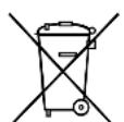
If you wish to finally dispose of the product, ask your local recycling centre or specialist dealer for details about how to do this in accordance with the applicable disposal regulations.
12 Technical data
| M55LX AHD M75LX | AHD | |
| Ref. no.: 9600012883 9600012899 | ||
| Type: Colour TFT LCD | ||
| Display size: 5" (12.7 cm) 7" (17.8 cm) | ||
| Brightness: approx. 350 cd/m2 | approx. 800 cd/m2 | |
| Display resolution: | 384,000 pixels | >600,000 pixels |
| Video standard: | 1080p30 / 1080p25 / 720p30 / 720p25 / PAL / NTSC (automatic switching) | |
| Operating voltage: | 12 - 30 V== | |
| Power: | max. 10 W | |
| Operating temperature: | -20 °C to 70 °C | |
| Storage temperature: | -30 °C to 70 °C | |
| Humidity: max. 85% | ||
| Vibration resistance: 6 g | ||
| Dimensions in mm W x H x D: | 146 x 87 x 26 | 190 x 110 x 26 |
| Weight: 350 g 400 g | ||
Approvals
The device has E13 certification.
6 Description technique
Connect the device to the housing properly!
When disconnecting the negative terminal of the battery, all energy-dependent memory devices of the vehicle's electronic systems may lose the data stored in them.
Depending on the fuel type, you may need to reconfigure the following data:
6.1 Description of operation
The monitor is a monitor to which cameras (e.g., video systems for rear view) or other video sources (e.g., DVD players) can be connected. It is possible to switch back and forth between video sources.
The monitor offers control lines that can be used to automatically activate cameras.
The monitor can work with four cameras. In addition to normal control, the four cameras can be activated automatically one after another. The monitor also has a programmable distance indicator that is automatically activated when reverse gear is engaged (CAM1).
The monitor display can be protected from the sun with a sun visor.
6.2 Control elements
The monitor has the following control elements:
7 Installation of the monitor
7.1 Required tools (Fig. 1, page 3)
The following tools are required for installation:
- Pliers (4) - Center punch (5) - Hammer (6) - Drill bit set (7) - Screwdriver (8) - File (9)
For electrical connection and testing, the following auxiliary means are required:
- Bottom control lamp (1) and voltmeter (2)
- Mounting tape (10) Heat-shrink tubing
- Industrial (11)
- Clamping pliers (12) - Under certain conditions, finger guard (13) - Under certain conditions, soldering iron (14)
- If necessary, cable feed-throughs
For cable fastening, cable ties may also be required.
7.2 Monitor mounting

CAUTION! Risk of injury!
Choose the mounting location for the monitor such that under no conditions (e.g., sudden braking, accident) there is a risk of injury to passengers.
When mounting, observe the following instructions:
- Choose a suitable mounting location that ensures an unobstructed view of the monitor (Fig. 6 and Fig. 7, item 4). Do not mount the monitor in the head impact zone or within the deployment range of the airbags. Otherwise, there is a risk of injury in the event of an accident.
- The monitor must not restrict visibility when driving the vehicle (Fig. 8, page 5).
- The mounting location must be flat.
- Make sure that there is sufficient free space behind the chosen mounting location for installing the nuts.
- Preliminarily check that there is enough free space for the drill bit to exit (Fig. 2, item 4).
- Weigh the monitor. If necessary, provide reinforcement (larger loads or brackets).
- Make sure that the cable can be routed to the monitor.
Determine the mounting location (Fig. 11, page 7)
Install the monitor on the bracket. During the test, place the monitor with the bracket base installed. Mark the contours of the bracket base on the instrument panel. Remove the monitor from the bracket.
Attaching the monitor bracket to the instrument panel (Fig. 12, page 7)
Install the bracket base within the previously marked contours. Secure the monitor bracket with self-tapping screws.
Mounting the monitor
Install the monitor on the bracket and fix it by turning it slightly (Fig. 11, page 7). Insert the latches over the bracket into the monitor.
7.3 Electrical connection of the monitor
The connection diagram for the monitor is shown in Fig. 14, page 8.
| № HaIMeHOBaHne | |
| 1 MoHITop | |
| 2 20-koHT. pa3bem | |
| 3 Пиня пITAня мОнITopa | |
| 4 20-koHT. shTekep | |
| 5 | ПоJOxHtBel'ый Ka6eB 12 - 24В (Крась):princseDInHeHne КпоJOxHtBel'Homу поюсу сисмБ 3axHraHnY (ВКПЮчЕНь «ППOC», ЗжIM 15) ип KпоJOxHtBel'Homу поюсу 6aTapeN (ЗжIM 30) |
| 6 Ka6eBдЯ coEДINeHnY c Koprnycom (Черны):princseDInHne К оТрцatelbHOMU поюсу nSTOChnka habржЕнry | |
| 7 Ka6eB (Зелень):ВхOD сИгнада унразовпенья дя вideobxODa CAM1, Нанример, дя princseDInHneK φаре 3aДнeroхODa | |
| 8 Ka6eB (6eIb):ВхOD сИгнада унразовпенья дя вideobxODa CAM2, Нанример, bokoboi KaMepbI | |
| 9 6-koHT. pa3bem CAM1 (princseDInHneK nSTOChNky вideocnHaJa 1) | |
| 10 6-koHT. pa3bem CAM2 (princseDInHneK nSTOChNky вideocnHaJa 2) | |
| 11 6-koHT. pa3bem CAM3 (princseDInHneK nSTOChNky вideocnHaJa 3) c paSINOZHaBaHnEM BnDEOCnHaJa | |
| 12 6-koHT. pa3bem CAM4 (princseDInHneK nSTOChNky вideocnHaJa 4, c paSINOZHaBaHnEM BnDEOCnHaJa) | |
| 13 Ka6eB (сinи):ВхOD сИгнада унразовпенья дя вideobxODa CAM3 Еси сисема akTIBnPyETcя чepe3 3ТOT урразвл Anyшпй рpoВOD,TO BCE КнОПКИ OCTAJOТС 6e3 Функши (coIpaCHO DIN EN 1501-1). | |

ATTENTION!
Incorrect routing and connection of cables lead to permanent failures and damage to parts.
Proper routing and connection of cables is the main condition for long-term, trouble-free operation of the installed components.
When routing connecting cables, follow these guidelines:
- For connecting cables, use, if possible, existing through holes, for example, ventilation grilles. If there are no through holes, it is necessary to drill a 22 mm hole. First check that there is enough free space for the drill exit (Fig. 2, page 4).
Make the hole with the lead-in (Fig. 12 1, p. 7) in the base plate of the monitor bracket. - To avoid cable damage, always maintain sufficient distance from hot vehicle components (lights, heater, fans, etc.) when laying cables. - When laying cables (Fig. 3, p. 4), ensure that they
-are not bent or kinked, -do not rub against edges, -are not laid without protection through lead-ins with sharp edges.
Connecting the monitor as a rear view camera system (Fig. 14, p. 8)
Connect the monitor's connecting cable to the device panel. Insert the monitor cable plug (2) into the socket (4) of the connecting cable (3).
The plug must click into place with a characteristic sound.

WARNING! Risk of damage!
When connecting to the power source, ensure correct polarity.
Connect the red and black cables of the connecting cable to the appropriate power source:
-Connect the red cable (5) to terminal 15 (ignition). -Connect the black cable (6) to terminal 31 (ground).
If the monitor is to be activated when the reverse gear is engaged, connect the green cable (7) to the positive wire of the reverse light.

NOTE
When voltage is applied to the green cable (7), the rear view camera is activated. The rear view camera has priority.
If the monitor is to be activated, for example, when the turn signal indicators are switched on, connect the following control cable to the positive wire of the turn signal indicators:
- white cable (8), blue cable (13)

NOTE
This control cable is supplied with power, so the CAM2 and CAM3 video inputs are activated.
This control cable is also used for signal transmission, for example, to activate the side camera when the turn signal indicators are switched on.
If necessary, connect the CAM1 socket (9) of the connecting cable to the connector of video signal source 1 (for example, a rear view camera). If necessary, connect the CAM2 socket (10) of the connecting cable to the connector of video signal source 2 (for example, a side camera).
If necessary, connect the CAM3 socket (11) of the connecting cable to the connector of video signal source 3 (for example, a camera).

NOTE
Consider the current consumption of the video system. The cameras are equipped with heaters. The current may be up to 1.5 A (in camera heating mode). When connecting directly to the battery, use a separator. This allows you to quickly disconnect the video system from the battery if the vehicle is not used for a long time.
Connecting an additional rear view camera (operating mode with a trailer)
If necessary, connect the CAM4 socket (12) of the connecting cable to the connector of the additional rear view camera.
9 Care and cleaning of the LCD monitor

CAUTION! Risk of damage!
The warranty period is established by law. If the product is defective, contact the manufacturer's representative in your country (addresses are on the back of the manual) or the dealer.
For repair or warranty service, you may also send the following:
Defective components, a copy of the receipt with the date of purchase, and a description of the malfunction.
Disposal
Where possible, dispose of packaging materials in the recycling bin.
At the end of the product's service life, please dispose of it properly. Contact your local recycling center or dealer for information on how to dispose of it in accordance with applicable regulations.
12 Technical data
dometic.com/sales-offices
- TABLE OF CONTENTS
- EXPLANATION OF SYMBOLS
- CAUTION
- NOTICE
- NOTE
- SAFETY AND INSTALLATION INSTRUCTIONS
- PLEASE OBSERVE THE SAFETY INSTRUCTIONS AND STIPULATIONS ISSUED BY THE VEHICLE MANUFACTURER AND SERVICE WORKSHOPS
- NOTICE! BEWARE OF DAMAGE
- ACCESSORIES
- TECHNICAL DESCRIPTION
- FUNCTION DESCRIPTION
- CONTROL ELEMENTS
- INSTALLING THE LCD MONITOR
- TOOLS REQUIRED (FIG. 1, PAGE 3)
- INSTALLING THE MONITOR
- CAUTION! BEWARE OF INJURY
- CHOOSING THE INSTALLATION LOCATION (FIG. 11, PAGE 7)
- SCREWING THE MONITOR BRACKET ONTO THE DASHBOARD (FIG. 12, PAGE 7)
- FASTENING THE MONITOR
- CONNECTING THE MONITOR ELECTRICALLY
- NO. DESCRIPTION
- CONNECTING THE MONITOR AS A REVERSING VIDEO SYSTEM (FIG. 14, PAGE 8)
- CONNECTING AN ADDITIONAL REVERSING CAMERA (TRAILER OPERATION)
- USING THE LCD MONITOR
- SWITCHING ON THE MONITOR
- SWITCHING OFF THE MONITOR
- SETTING THE MONITOR
- PAGE 1: PICTURE
- PAGE 2: OPTIONS
- PAGE 3: AUTO SEARCH
- SETTING THE VIDEO SOURCE
- SETTING THE AUTOMATIC SEARCH
- SETTING THE DISPLAY TIME
- QUITTING THE AUTOMATIC SEARCH
- DETECTING THE TRAILER CAMERA
- SETTING THE DISTANCE MARKERS
- CLEANING AND CARING FOR THE LCD MONITOR
- WARRANTY
- DISPOSAL
- TECHNICAL DATA
- APPROVALS
- DESCRIPTION TECHNIQUE
- DESCRIPTION OF OPERATION
- INSTALLATION OF THE MONITOR
- REQUIRED TOOLS (FIG. 1, PAGE 3)
- MONITOR MOUNTING
- CAUTION! RISK OF INJURY
- DETERMINE THE MOUNTING LOCATION (FIG. 11, PAGE 7)
- ATTACHING THE MONITOR BRACKET TO THE INSTRUMENT PANEL (FIG. 12, PAGE 7)
- MOUNTING THE MONITOR
- ELECTRICAL CONNECTION OF THE MONITOR
- ATTENTION
- CONNECTING THE MONITOR AS A REAR VIEW CAMERA SYSTEM (FIG. 14, P. 8)
- WARNING! RISK OF DAMAGE
- CONNECTING AN ADDITIONAL REAR VIEW CAMERA (OPERATING MODE WITH A TRAILER)
- CARE AND CLEANING OF THE LCD MONITOR
- CAUTION! RISK OF DAMAGE
Brand : DOMETIC
Model : PerfectView BVS 71000
Category : LCD Screen