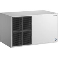
KM-590DJE-R452 - Ice Maker Hoshizaki - Free user manual and instructions
Find the device manual for free KM-590DJE-R452 Hoshizaki in PDF.


| Product Type | Air-cooled professional ice machine |
| Model | KM-590DJE-R452 |
| Brand | Hoshizaki |
| Ice Production | 630 kg per 24 h (ambient temp. 10 °C, water 10 °C) |
| Ice Type | Crescent ice cubes |
| Dimensions (W x D x H) | 1219 mm x 695 mm x 695 mm |
| Net Weight | 136 kg |
| Power Supply | 1 phase 220 - 240 V 50 Hz, 3.64 kVA (15.8 A) |
| Power Consumption | 2080 W (ambient temp. 32 °C, water 21 °C) |
| Refrigerant | R452A, 1.90 kg (GWP 2140) |
| Ambient Temperature Range | 7 to 38 °C |
| Water Temperature Range | 7 to 32 °C |
| Water Pressure Required | 0.07 to 0.8 MPa (0.7 to 8 bar) |
| Cleaning and Disinfection | Recommended at least once a year; detailed procedure in the manual |
| Air Filter Maintenance | Check at least twice a month; wash with warm water and mild detergent |
| Warranty | 2 years from the date of installation |
Frequently Asked Questions - KM-590DJE-R452 Hoshizaki
User questions about KM-590DJE-R452 Hoshizaki
0 question about this device. Answer the ones you know or ask your own.
Ask a new question about this device
Download the instructions for your Ice Maker in PDF format for free! Find your manual KM-590DJE-R452 - Hoshizaki and take your electronic device back in hand. On this page are published all the documents necessary for the use of your device. KM-590DJE-R452 by Hoshizaki.
USER MANUAL KM-590DJE-R452 Hoshizaki
STACKABLE CRESCENT CUBER
MACHINE A GLACONS CROISSANT EMPILABLE
(original instructions)
NOTICE D'UTILISATION
Important Safety Information....1
I. Specifications 4
A. Electrical and Refrigerant Data....4
B. Dimensions/Connections....5
II. Installation and Startup Instructions 6
A. Checks Before Installation....6
B. How to Remove Panels 6
C. Location....6
D. Setup 7
E. Installation of Upper Unit 8
F. Electrical Connection....9
G. Water Supply and Drain Connections 10
H. Final Checklist....11
I. Startup 12
III. Cleaning and Maintenance Instructions 12
A. Cleaning and Sanitizing Instructions 12
B. Maintenance....14
C. Preparing the Icemaker for Long Storage 14
IV. WARRANTY 15
V. DISPOSAL....15
FRANÇAIS
V. MISE AU REBUT....30
DEUTSCH
This manual should be read carefully before the appliance is installed and operated. Read the warnings and guidelines contained in this manual carefully as they provide essential information for the continued safe use and maintenance of the appliance. Retain this manual for any further reference that may be necessary.
Important Safety Information
Throughout this manual, notices appear to bring your attention to situations which could result in death, serious injury, damage to the appliance, or damage to property.
⚠ WARNING Indicates a hazardous situation which could result in death or serious injury.
NOTICE Indicates a situation which could result in damage to the appliance or property.
IMPORTANT Indicates important information about the installation, use, and care of the appliance.
CAUTION Indicates a hazardous situation which, if not avoided, could result in minor or moderate injury.
WARNING
The appliance should be destined only to the use for which it has been expressly conceived. Any other use should be considered improper and therefore dangerous. The manufacturer cannot be held responsible for injury or damage resulting from improper, incorrect, and unreasonable use. Failure to install, operate, and maintain the appliance in accordance with this manual will adversely affect safety, performance, component life, and warranty coverage and may result in costly water damage.
To reduce the risk of death, electric shock, serious injury, or fire, follow basic precautions including the following:
- Only qualified service technicians should install and service the appliance.
- The appliance must be installed in accordance with applicable national, state, and local codes and regulations.
- Electrical connection must be hard-wired and must meet national, state, and local electrical code requirements. Failure to meet these code requirements could result in death, electric shock, serious injury, fire, or damage.
- The icemaker requires an independent power supply of proper capacity. See the specifications in this manual. Failure to use an independent power supply of proper capacity can result in a tripped breaker, blown fuse, damage to existing wiring, or component failure. This could lead to heat generation or fire.
- THE ICEMAKER MUST BE GROUNDED. Failure to properly ground the icemaker could result in death or serious injury.
- To reduce the risk of electric shock, do not touch the control switch with damp hands.
- Move the control switch to the "OFF" position and turn off the power supply before servicing. Lockout/Tagout to prevent the power supply from being turned back on inadvertently.
- Do not make any alterations to the appliance. Alterations could result in electric shock, serious injury, fire, or damage.
- The appliance is not intended for use by persons (including children) with reduced physical, sensory, or mental capabilities, or lack of experience and knowledge, unless they have been given supervision or instruction concerning use of the appliance by a person responsible for their safety.
• Children should be properly supervised around the appliance. - Do not climb, stand, or hang on the appliance or allow children or animals to do so. Serious injury could occur or the appliance could be damaged.
- Do not use combustible spray or place volatile or flammable substances near the appliance. They might catch fire.
- Keep the area around the appliance clean. Dirt, dust, or insects in the appliance could cause harm to individuals or damage to the appliance.
NOTICE
- Follow the water supply, drain connection, and maintenance instructions carefully to reduce the risk of costly water damage.
- In areas where water damage is a concern, install in a contained area with a floor drain.
• Install the icemaker in a location that stays above freezing. Normal operating ambient temperature must be within 7^ C to 38^ C. - Do not leave the icemaker on during extended periods of non-use, extended absences, or in sub-freezing temperatures. To properly prepare the icemaker for these occasions, follow the instructions in "III. C. Preparing the Icemaker for Long Storage."
- Do not place objects on top of the appliance.
- The dispenser unit/ice storage bin is for ice use only. Do not store anything else in the dispenser unit/ice storage bin.
I. Specifications
A. Electrical and Refrigerant Data
The nameplate provides electrical and refrigerant data. The nameplate is located on the left panel. For certification marks, see the nameplate.
We reserve the right to make changes in specifications and design without prior notice.
- KM-590DJE-R452
| Model KM-590DJE-R452 | |
| Type Air-cooled, crescent cube ice | |
| Power Supply 1 phase 220 - 240V | 50Hz |
| Power Supply Capacity 3.64kVA (15.8A) | |
| Electric Consumption 2080W (AT: | 32°C, WT: 21°C) |
| Ice Production per 24h 630kg (AT: | 10°C, WT: 10°C) |
| Dimensions 1219mm(W) x 695mm | (D) x 695mm(H) |
| Refrigerant | R452A1.90kg (GWP:2140, CO2: 4.066t) |
| Insulation Foam Blowing Agent Cyclopentane | |
| Weight Net: 136kg (Gross: 154kg) | |
| Ambient Temp 7 - 38°C | |
| Water Supply Temp 7 - 32°C | |
| Water Supply Pressure 0.07 - 0.8MPa (0.7 - 8bar) | |
| Voltage Range 198 - 254V | |
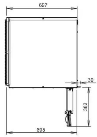
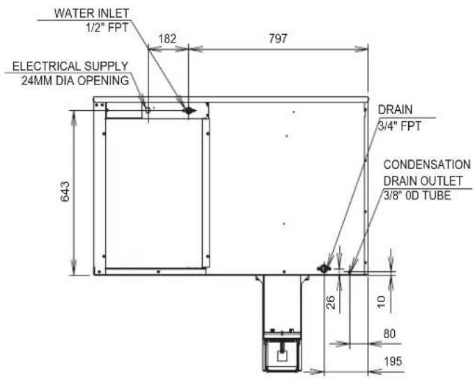
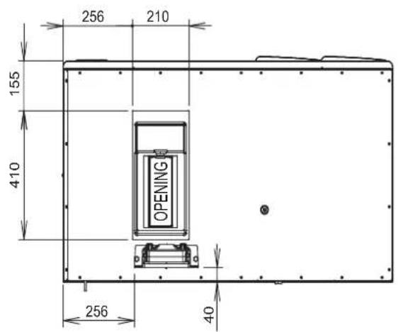
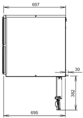
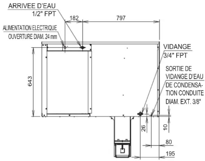
B. Dimensions/Connections
1. KM-590DJE-R452
Units: mm
Side
Rear
NOTICE
- KM-590DJE-R452: Allow 15cm clearance at rear, sides, and top for proper air circulation and ease of maintenance and/or service should they be required.
- The ice storage bin opening must match the bottom opening as in the illustration.
Bottom
II. Installation and Startup Instructions
WARNING
- This icemaker must be installed in accordance with applicable national, state, and local regulations.
- CHOKING HAZARD: Ensure all components, fasteners, and thumbscrews are securely in place after installation. Make sure that none have fallen into the storage bin.
A. Checks Before Installation
- Visually inspect the exterior of the shipping container and immediately report any damage to the carrier. Upon opening the container, any concealed damage should also be immediately reported to the carrier.
- Remove the shipping carton, tape, and packing material. If any are left in the icemaker, it will not work properly. WARNING! Keep packing material (plastic bags and expanded polystyrene) away from children.
- Remove the panels to prevent damage when installing the icemaker. See "II. B. How to Remove Panels."
- Remove the package containing the accessories.
- Remove the protective plastic film from the panels. If the icemaker is exposed to the sun or to heat, remove the film after the icemaker cools.
- Check that the refrigerant lines do not rub or touch lines or other surfaces.
- Check that the compressor is snug on all mounting pads.
- See the nameplate on the side panel, and check that your voltage supplied corresponds with the voltage specified on the nameplate.
- This icemaker can be installed on a storage bin 48" wide or wider. For options, contact your local Hoshizaki distributor.
B. How to Remove Panels
See Fig. 1
- Front Panel: Remove the 2 screws. Lift up and towards you.
- Top Panel: Remove the 2 screws, then lift off.
- Side Panel (R): Remove the screw. Slide forward slightly and lift off.
• Insulation Panel: Remove the thumbscrew. Lift up slightly and pull towards you.
• Top Insulation: Lift off.
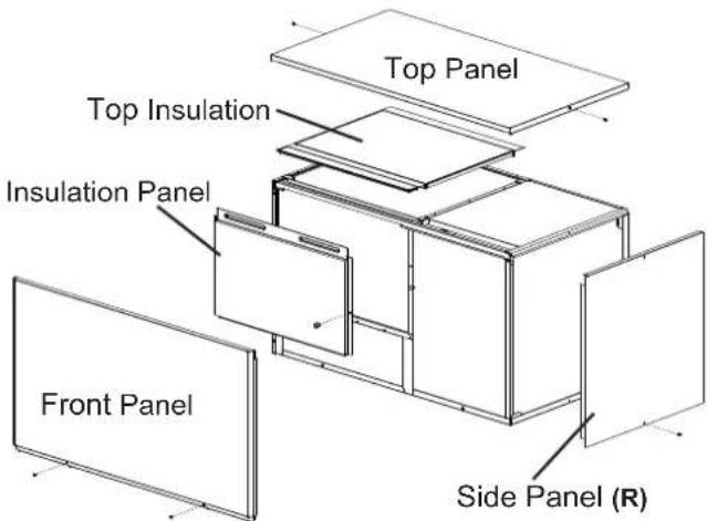
Fig. 1
C. Location
CAUTION
- This icemaker is not intended for outdoor use. Normal operating ambient temperature should be within 7°C to 38°C; Normal operating water temperature should be within 7°C to 32°C.
Operation of the icemaker, for extended periods, outside of these normal temperature ranges may affect icemaker performance. - This icemaker will not work at sub-freezing temperatures. To prevent damage to the water supply line, drain the icemaker if the air temperature is going to go below 0°C. For details, see "III. C. Preparing the Icemaker for Long Storage."
For best operating results:
- The icemaker should not be located next to ovens, grills, or other high heat producing equipment.
- The location should provide a firm and level foundation for the equipment.
- Allow 15cm clearance at rear, sides, and top for proper air circulation and ease of maintenance and/or service should they be required.
D. Setup
CAUTION
Before operating the icemaker, the bin control assembly must be installed correctly. Failure to properly install the assembly could result in ice backup and unit damage.
1) Follow the storage bin's setup procedure.
2) Position the storage bin in the selected permanent location.
3) Place the icemaker on top of the storage bin.
4) Secure the icemaker to the storage bin using the 2 mounting brackets and the bolts provided. See Fig. 2.
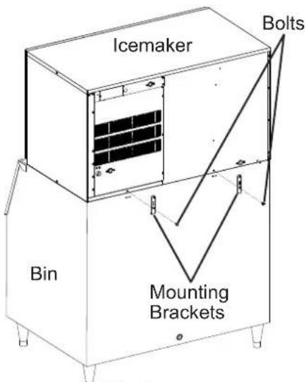
Fig. 2
5) Install the bin control assembly as follows:
a. Remove the baffle from the storage bin.
b. Remove the thumbscrew and bin control assembly from inside the icemaker. See Fig. 3.

Fig. 3
c. Use the thumbscrew removed in the previous step and the thumbscrew included in the accessory bag to secure the bin control assembly to the bottom of the icemaker. See Fig. 4.
d. Remove the bin control cable bracket from inside the icemaker, then route the bin control cable through the hole in the bin control bracket and the hole in the bottom of the icemaker. Route the cable through the bushing in the bin control cable bracket, then secure the bracket. Leave as little slack as possible inside the storage bin. Route the cable through the wire saddles.
e. Connect the bin control cable connector to wire harness connector A coming from the control box.
Note:
- Wire harness has one connector to plug into the bin control cable and another connector for use if an upper unit is installed.
- Wire harness is connected to the control board red K4 connector.
f. Make sure the bin control cable and wire harness are secured in the wire saddles and do not interfere with any components.
Connection Overview
Bin Control Cable Connector/Wire Harness Connector A
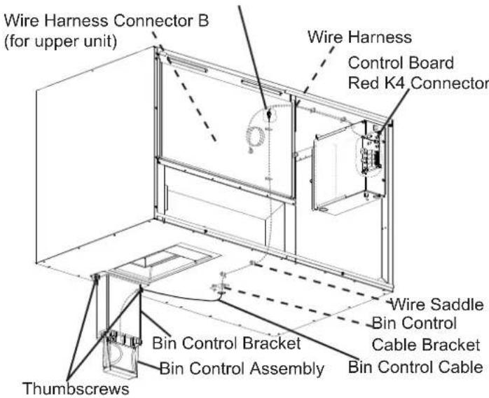
Connection Detail

Fig. 4
6) Level the icemaker and storage bin in both the left-to-right and front-to-rear directions. Adjust the storage bin legs to make the icemaker level.
7) Replace the panels and storage bin baffle in their correct positions unless you are installing an upper unit. If installing an upper unit, see "II. E. Installation of Upper Unit."
E. Installation of Upper Unit
1) See "II. D. Setup" for the lower unit installation.
2) Remove the top panel and the top insulation of the lower unit. The top panel and the top insulation of the lower unit are not required when installing an upper unit.
3) Unpack the upper unit and remove the shipping carton, tape, and packing material.
4) Remove the panels of the upper unit.
5) Stack the upper unit on top of the lower unit.
6) Secure the upper unit to the lower unit using the 2 mounting brackets and the bolts provided. See Fig. 5.
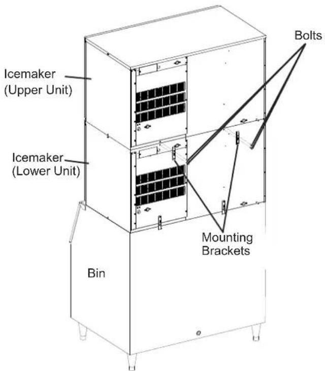
Fig. 5
7) Remove the bin control cable bracket from inside the upper unit. See Fig. 6. Leave the upper unit's bin control assembly in its original position. It will not be used.
8) Route lower unit wire harness connector B through the hole in the bottom of the upper unit. Route the wiring through the bushing in the bin control cable bracket, then through the wire saddles.
9) Connect lower unit wire harness connector B to upper unit wire harness connector A.
Note: Wire harness is connected to the control board red K4 connector.
10) Make sure the wire harnesses are secured in the wire saddles and do not interfere with any components.
11) Secure the bin control cable bracket.
12) Replace the panels and storage bin baffle in their correct positions.
Upper Unit Connection Overview
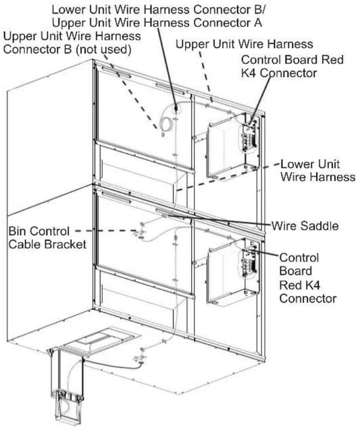
Upper Unit Connection Detail
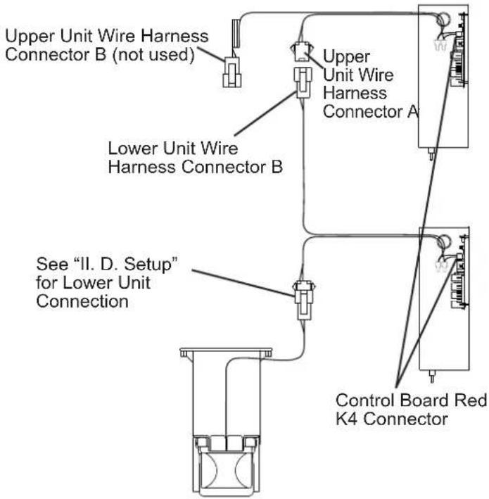
Fig. 6
F. Electrical Connection
WARNING
For All Models
- Hard-wired electrical connection is recommended. Electrical connection must meet national, state, and local electrical code requirements. Failure to meet these code requirements could result in death, electric shock, serious injury, fire, or severe damage to equipment.
- This unit requires an independent power supply of proper capacity. See the nameplate for electrical specifications. Failure to use a properly sized breaker or fuse can result in a tripped breaker, blown fuses, or damage to existing wiring. This could lead to heat generation or fire.
- THIS UNIT MUST BE GROUNDED (EARTHED).
Failure to properly ground (earth) this unit could result in death or serious injury.
• Usually an electrical permit and services of a licensed electrician are required.
- The maximum allowable voltage variation is ±10 percent of the nameplate rating.
- The neutral terminal on the terminal block (light blue wire) must be connected to the neutral conductor of the power source. See Fig. 7. CAUTION! Miswiring may result in severe damage to the icemaker.
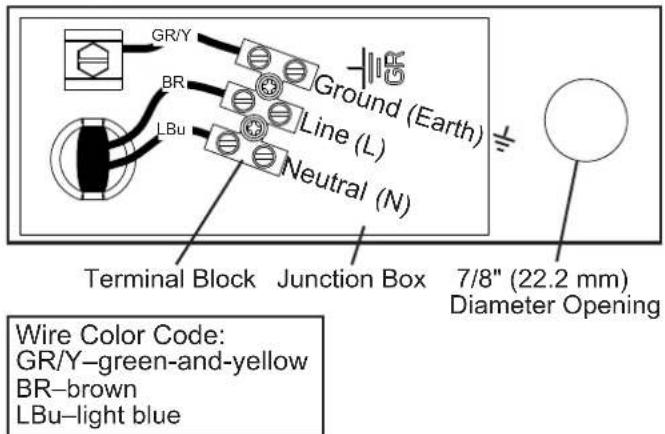
Fig. 7
- The opening for the power supply connection is 7/8" (22.2mm) DIA to fit a 1/2" trade size conduit.
- If a power cord is used to provide electricity to the icemaker in place of a hard-wired (conduit) connection, a strain relief (gland) of the appropriate size for the power cord must be installed at the 7/8" (22.2 mm) diameter opening for the power supply connection.
WARNING! The power cord and its conductors must be appropriately sized and rated for the electrical consumption of this icemaker. See the nameplate for electrical specifications.
For the UK and the Republic of Ireland Only
For installations to pre-IEC 60446 field wiring, the colors of the wires in the icemaker's junction box may not correspond with the colors of the field wiring. In this case, proceed as follows:
The icemaker terminal with the green-and-yellow wire must be connected to the incoming green or green-and-yellow wire which connects to the terminal marked with the letter "E", the symbol 1 or the color green or green-and-yellow. The icemaker terminal with the light blue wire must be connected to the incoming black wire which connects to the terminal marked with the letter "N" or the color black. The icemaker terminal with the brown wire must be connected to the incoming red wire which connects to the terminal marked with the letter "L" or the color red.
G. Water Supply and Drain Connections See Fig. 8.
WARNING
- Water supply and drain connections must be installed in accordance with applicable national, state, and local regulations.
- The icemaker water supply must be potable water.
- Normal operating water temperature should be within 7^ C to 32^ C. Operation of the icemaker, for extended periods, outside of this normal temperature range may affect icemaker performance.
- Water supply pressure should be a minimum of 0.07MPa (0.7 bar) and a maximum of 0.78MPa (7.8 bar). If the pressure exceeds 0.78MPa (7.8 bar), the use of a pressure reducing valve is required. DO NOT throttle back the supply tap.
- To prevent damage to equipment, do not operate the icemaker when the water supply is off, or if the pressure is below 0.07MPa (0.7 bar). Do not run the icemaker until the proper water pressure is reached.
-
This icemaker will not work at sub-freezing temperatures. To prevent damage to the water supply line, drain the icemaker if the air temperature is going to go below 0°C. For details, see "III. C. Preparing the Icemaker for Long Storage."
-
External filters, strainers, or softeners may be required depending on water quality. Contact your local Hoshizaki distributor for recommendations.
- The icemaker and condensation drain line(s), storage bin drain line, and water-cooled condenser drain line (if applicable) must be run separately. When stacking units, each unit must have independent drain lines.
- Drain lines must have 2cm tall per 1 m on horizontal runs to get a good flow. A vented tee connection is also required for proper flow.
- Drain lines should not be piped directly to the sewer system. An air gap of a minimum of 5 vertical centimeter should be between the end of the drain pipes from the icemaker and condensation drain, storage bin, and water-cooled condenser (if applicable) and the floor drain.
1. Icemaker
- Icemaker water supply inlet is 1/2" female pipe thread (FPT). A minimum of 3/8" (10mm) nominal copper water tubing is recommended for the icemaker water supply line.
- An icemaker water supply line shut-off valve and drain valve should be installed. A ball valve is recommended for the shut-off valve. If another type of valve is used, it should not have an opening smaller than the water supply line ID as this can cause a reduced water flow rate which can lead to poor harvest performance and/or freeze up.
- Icemaker drain outlet is 3/4" FPT. A minimum of 3/4" (18mm) nominal hard pipe is recommended for the icemaker drain line. Condensation drain outlet is 3/8" (9.5mm) OD hard tube. The condensation drain line can be connected to the icemaker drain line or can be run separately.
- A plumbing permit and services of a licensed plumber may be required in some areas.
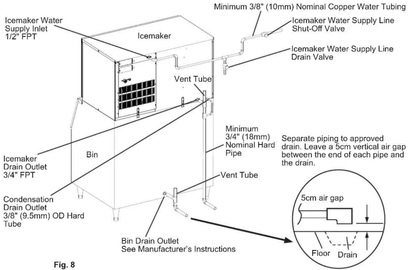
KM-590DJE-R452
H. Final Checklist
WARNING
CHOKING HAZARD: Ensure all components, fasteners, and thumbscrews are securely in place after installation. Make sure that none have fallen into the storage bin.
1) Is the icemaker level?
2) Is the icemaker in a site where the ambient temperature is within 7^ C to 38^ C and the water temperature within 7^ C to 32^ C all year around?
3) Is there at least 15cm clearance at sides, rear, and top of the icemaker for proper air circulation and ease of maintenance and service?
4) Have the shipping carton, tape, and packing material been removed from the icemaker? Are the cube guides in their correct positions? See Fig. 9. Are the separators between the evaporator banks properly attached to their holding clips?
5) Are all components, fasteners, and thumbscrews securely in place?
6) Have all electrical and water connections been made? Do electrical and water connections meet all national, state, and local code and regulation requirements?
7) Has the power supply voltage been checked or tested against the nameplate rating? Has a proper ground (earth) been installed to the icemaker? On remote air-cooled model, has a proper ground (earth) also been installed to the remote condenser unit?
8) Are the water supply line shut-off valves and drain valves installed? Has the water supply pressure been checked to ensure a minimum of 0.07MPa (0.7 bar) and a maximum of 0.78MPa (7.8 bar)?
Note: The icemaker may stop running when the water supply is off, or if the pressure is below 0.07MPa (0.7 bar). When the proper water pressure is reached, the icemaker automatically starts running again.
9) Are the compressor hold-down bolts snug? Have the refrigerant lines been checked to make sure they do not rub or touch other lines or surfaces? Have the fan blade(s) (if applicable) been checked to make sure they turn freely?
10) On remote air-cooled model, is the refrigerant line set tightened and free of leaks and kinks?
11) Has the end user been given the instruction manual, and instructed on how to operate the icemaker and the importance of the recommended periodic maintenance? Upon completion of startup, this installation manual should also be given to the end user.
12) Has the end user been given the name and telephone number of an authorized service agent?
13) Has the warranty card been filled out and forwarded to the factory for warranty registration?
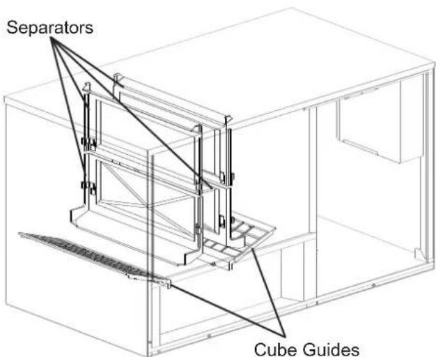
Fig. 9
I. Startup
WARNING
- All parts are factory-adjusted. Improper adjustments may adversely affect safety, performance, component life, and warranty coverage.
- If the icemaker is turned off, wait for at least 3 minutes before restarting the icemaker to prevent damage to the compressor.
- To prevent damage to the water pump, do not leave the control switch in the "WASH" position for extended periods of time when the water tank is empty.
- On remote air-cooled model, the icemaker should have power for a minimum of 4 hours prior to startup to prevent compressor damage.
- At startup, confirm that all internal and external connections are free of leaks.
1) Open the water supply line shut-off valve(s).
2) Remove the front panel.
3) Move the control switch on the control box to the "ICE" position.
4) Replace the front panel in its correct position.
5) Turn on the power supply, and allow the icemaker to operate for a total of 10 minutes.
6) Turn off the power supply, then remove the front panel.
7) Remove the insulation panel. Remove the drain plug located on the lower front part of the ice chute. See Fig. 10. Allow the water tank to drain.
8) Replace the drain plug, insulation panel, and front panel in their correct positions. Be careful not to cross thread the drain plug.
9) Clean the storage bin liner using a neutral cleaner. Rinse thoroughly after cleaning.
10) Turn on the power supply to start the automatic icemaking process.
11) To confirm bin control operation, press and hold the bin control's actuator paddle during the first 5 minutes of the freeze cycle. The icemaker should shut down in approximately 15 seconds.
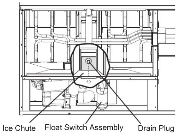
Fig. 10
III. Cleaning and Maintenance Instructions
This icemaker must be cleaned and maintained in accordance with the documentation and labels provided with the icemaker. Consult with your local distributor about cleaning and maintenance service. To obtain the name and phone number of your local distributor, contact your nearest Hoshizaki Service office.
WARNING
- Except as specified below, only qualified service technicians should attempt to service this icemaker.
- CHOKING HAZARD: Ensure all components, fasteners, and thumbscrews are securely in place after any cleaning or maintenance is done to the unit. Make sure that none have fallen into the storage bin.
- This appliance must not be cleaned by use of a water jet.
- To prevent possible damage, do not clean the plastic parts with water above 40^ C or in a dishwasher.
- The storage bin is for ice use only. Do not store anything else in the storage bin.
A. Cleaning and Sanitizing Instructions Performed by Qualified Service Technician
Hoshizaki recommends cleaning and sanitizing this unit at least once a year. More frequent cleaning and sanitizing, however, may be required in some existing water conditions.
WARNING
- To prevent injury to individuals and damage to the icemaker, do not use ammonia type cleaners.
- Carefully follow any instructions provided with the bottles of cleaning and sanitizing solution.
- Always wear liquid-proof gloves and goggles to prevent the cleaning and sanitizing solutions from coming into contact with skin or eyes.
- To prevent damage to the water pump seal, do not operate the icemaker with the control switch in the "WASH" position when the water tank is empty.
IMPORTANT
-
The cleaning valve is opened during cleaning and sanitizing to allow solution flow to the inside of the evaporator. It should be closed for all icemaking operation. The compressor will not operate unless this valve is completely closed.
-
To close the cleaning valve, the valve handle should be at a right angle to the valve body. To open the cleaning valve, the valve handle should be parallel to the valve body.
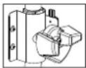
CLOSED
Icemaking Operation
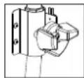
Cleaning and Sanitizing Operation (allows solution flow to the inside of the evaporator)
1. Cleaning Procedure
1) Dilute 800 ml of Hoshizaki "Scale Away" with 19 L of warm water or prepare the other recommended Hoshizaki sanitizer as detected.
2) Remove all ice from the evaporator and the storage bin.
Note: To remove cubes on the evaporator, turn off the power supply and turn it back on after 3 minutes. The harvest cycle starts and the cubes will be removed from the evaporator.
3) Turn off the power supply.
4) Remove the front panel, then remove the insulation panel by first removing the thumbscrew, lifting up the panel slightly and pulling it towards you.
5) Remove the drain plug located on the lower front part of the ice chute. See Fig. 10. Allow the water tank to drain.
6) Replace the drain plug in its correct position. Be careful not to cross thread it.
7) In bad or severe water conditions, clean the float switch assembly as described below. Otherwise, continue to step 8.
a. Disconnect the vent tube and the flush tube from the top of the float switch, then remove the float switch assembly. Remove the rubber boot from the bottom of the assembly.
b. Remove the retainer rod from the bottom of the float switch housing, then remove the float. Be careful not to bend the retainer rod excessively when removing it.
c. Wipe down the float switch assembly's housing, shaft, float, and retainer rod with cleaning solution. Clean the inside of the rubber boot and hose with cleaning solution. Rinse the parts thoroughly with clean water.
d. Reassemble the float switch assembly and replace it and the rubber boot in their correct positions. Reconnect the vent tube and the flush tube.
8) Pour the cleaning solution into the water tank.
9) Move the control switch on the control box to the "WASH" position.
10) Replace the insulation panel and the front panel in their correct positions.
11) Turn on the power supply to start the washing process.
12) Turn off the power supply after 30 minutes.
13) Remove the front panel and the insulation panel.
14) Remove the drain plug. Allow the water tank to drain. Replace the drain plug and the insulation panel in their correct positions.
15) Move the control switch to the "ICE" position.
16) Replace the front panel in its correct position.
17) Turn on the power supply to fill the water tank with water.
18) Turn off the power supply after 3 minutes.
19) Remove the front panel.
20) Move the control switch to the "WASH" position.
21) Replace the front panel in its correct position.
22) Turn on the power supply to rinse off the cleaning solution.
23) Turn off the power supply after 5 minutes.
24) Remove the front panel and the insulation panel.
25) Remove the drain plug. Allow the water tank to drain. Replace the drain plug and the insulation panel in their correct positions.
Note: Do not replace the insulation panel when you proceed to "2. Sanitizing Procedure."
26) Repeat steps 15 through 25 three more times to rinse thoroughly.
Note: If you do not sanitize the icemaker, go to step 9 in "2. Sanitizing Procedure."
2. Sanitizing Procedure - Following Cleaning Procedure
1) Dilute 74 ml or 5 tbs of a 5.25% sodium hypochlorite solution (chlorine bleach) with 19 L of warm water.
2) Pour the sanitizing solution into the water tank.
3) Replace the insulation panel and the front panel in their correct positions.
Note: Make sure the control switch is in the "WASH" position.
4) Turn on the power supply to start the sanitizing process.
5) Turn off the power supply after 15 minutes.
6) Remove the front panel and the insulation panel.
7) Remove the drain plug. Allow the water tank to drain. Replace the drain plug and the insulation panel in their correct positions.
8) Repeat steps 15 through 25 in "1. Cleaning Procedure" two times to rinse thoroughly.
9) Move the control switch to the "ICE" position.
10) Replace the front panel in its correct position.
11) Clean the storage bin liner using a neutral cleaner. Rinse thoroughly after cleaning.
12) Turn on the power supply to start the automatic icemaking process.
B. Maintenance
The maintenance schedule below is a guideline. More frequent maintenance may be required depending on water quality, the icemaker's environment, and local sanitation regulations.
WARNING
- Except as specified below, only qualified service technicians should attempt to service this icemaker.
- Move the power switch to the "OFF" position and disconnect power before servicing.
1. Stainless Steel Exterior - Performed by Qualified Service Technician or Owner/Manager
To prevent corrosion, wipe the exterior occasionally with a clean, soft cloth. Use a damp cloth containing a neutral cleaner to wipe off oil or dirt buildup.
2. Storage Bin and Scoop - Performed by Qualified Service Technician or Owner/Manager
Clean the scoop and the storage bin liner using a neutral cleaner. Rinse thoroughly after cleaning.
3. Air Filters - Performed by Qualified Service Technician or Owner/Manager
Plastic mesh air filters remove dirt and dust from the air and keep the condenser from getting clogged. As the filters get clogged, the icemaker's performance will be reduced. Check the filters at least twice a month. When clogged, use warm water and a neutral cleaner to wash the filters.
4. Condenser - Performed by Qualified Service Technician The condenser should be checked and cleaned once a year. Instructions for the service technician can be found in the Installation Manual supplied with this icemaker.
C. Preparing the Icemaker for Long Storage Performed by Qualified Service Technician
CAUTION
- When storing the icemaker for an extended time or in sub-freezing temperatures, follow the instructions below to prevent damage.
- To prevent damage to the water pump seal, do not operate the icemaker with the control switch in the "WASH" position when the water tank is empty.
When the icemaker is not used for two or three days under normal conditions, it is sufficient to move the control switch to the "OFF" position. When storing the icemaker for an extended time or in sub-freezing temperatures, follow the instructions below.
1. Remove the water from the icemaker water supply line:
1) Turn off the power supply, then remove the front panel.
2) Move the control switch on the control box to the "OFF" position.
3) Close the icemaker water supply line shut-off valve, then open the icemaker water supply line drain valve.
4) Allow the line to drain by gravity.
5) Attach a compressed air or carbon dioxide supply to the icemaker water supply line drain valve.
6) Move the control switch to the "ICE" position.
7) Replace the front panel in its correct position, then turn on
the power supply.
8) Blow the icemaker water supply line out using the compressed air or carbon dioxide supply.
9) Close the icemaker water supply line drain valve.
2. Drain the water tank:
1) Turn off the power supply, then remove the front panel. Move the control switch to the "OFF" position.
2) Remove the insulation panel. Remove the drain plug located on the lower front part of the ice chute. See Fig. 10. Allow the water tank to drain.
3) Replace the drain plug and the insulation panel in their correct positions. Be careful not to cross thread the drain plug.
4) Remove all ice from the storage bin. Clean the storage bin using a neutral cleaner. Rinse thoroughly after cleaning.
5) Replace the front panel in its correct position.
IV.WARRANTY
Hoshizaki warrants to the original owner/user that all Hoshizaki branded products shall be free of defects in material and/or workmanship for the duration of the "warranty period". The warranty shall be effective for two years from the date of installation.
Hoshizaki's liability under the terms of the warranty are limited and shall exclude routine servicing, cleaning, essential maintenance and/or repairs occasioned by misuse and installations not in accordance with Hoshizaki guidelines.
Warranty repairs should be completed by an approved Hoshizaki dealer or service agency using genuine Hoshizaki components.
To obtain full details of your warranty and approved service agency, please contact your dealer/supplier, or the nearest Hoshizaki Service office.
V.DISPOSAL
Comply with local regulations regarding disposal of this appliance and its refrigerant gas. Before you scrap the appliance, take off the door to prevent children trapped.
Correct disposal of this product:
This marking indicates that this product should not be disposed with other household wastes throughout the EU. To prevent possible harm to the environment or human health from uncontrolled waste disposal, recycle it responsibly to promote the sustainable reuse of material
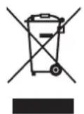
resources. To return your used device, use
the return and collection systems or contact the retailer where
the product was purchased. They can take this product for environmental safe recycling.
WARNING

The insulation foaming agent used for the unit body contains flammable gas cyclopentane.
With this in mind, dispose of the product properly.
IMPORTANT
B. Dimensions/Branchements
1. KM-590DJE-R452
Unités : mm
Côté
Arrière
AVIS
natural_image
Technical line drawing of an industrial piping system with a highlighted circular component (no text or symbols)LET OP
natural_image
Technical line drawing of an industrial piping system with a highlighted circular component (no text or symbols)- NOTICE D'UTILISATION
- FRANÇAIS
- DEUTSCH
- Important Safety Information
- ⚠ WARNING Indicates a hazardous situation which could result in death or serious injury.
- WARNING
- To reduce the risk of death, electric shock, serious injury, or fire, follow basic precautions including the following:
- NOTICE
- Specifications
- Electrical and Refrigerant Data
- Dimensions/Connections
- KM-590DJE-R452
- Installation and Startup Instructions
- Checks Before Installation
- How to Remove Panels
- See Fig. 1
- Location
- CAUTION
- Setup
- Connection Overview
- Connection Detail
- Installation of Upper Unit
- Electrical Connection
- For All Models
- For the UK and the Republic of Ireland Only
- Water Supply and Drain Connections See Fig. 8.
- Icemaker
- Final Checklist
- Startup
- Cleaning and Maintenance Instructions
- Cleaning and Sanitizing Instructions Performed by Qualified Service Technician
- IMPORTANT
- Cleaning Procedure
- Sanitizing Procedure - Following Cleaning Procedure
- Maintenance
- Stainless Steel Exterior - Performed by Qualified Service Technician or Owner/Manager
- Storage Bin and Scoop - Performed by Qualified Service Technician or Owner/Manager
- Air Filters - Performed by Qualified Service Technician or Owner/Manager
- Condenser - Performed by Qualified Service Technician The condenser should be checked and cleaned once a year. Instructions for the service technician can be found in the Installation Manual supplied with this icemaker.
- Preparing the Icemaker for Long Storage Performed by Qualified Service Technician
- Remove the water from the icemaker water supply line:
- Drain the water tank:
- IV.WARRANTY
- V.DISPOSAL
- Dimensions/Branchements
- AVIS
- LET OP
Brand : Hoshizaki
Model : KM-590DJE-R452
Category : Ice Maker