
ESP-3020 - Power bank VOLTCRAFT - Free user manual and instructions
Find the device manual for free ESP-3020 VOLTCRAFT in PDF.

| Product type | Laboratory power supply |
| Brand | Voltcraft |
| Model | ESP-3020 |
| Output voltage | 0 – 30 V DC (variable) |
| Output current | 0 – 20 A DC (variable) |
| Maximum output power | 600 W |
| Mains supply | 200 – 240 V AC, 50/60 Hz, 4.5 A |
| Fuse | F10 A, 250 V AC |
| Protection class | I (with earth grounding) |
| Display | Digital: voltage and current indicators |
| Display accuracy | ±0.5 % ±1 digit |
| Operating modes | CV (constant voltage) and CC (constant current) |
| Overvoltage limit (O.V. Set) | 1.5 – 35 V DC (adjustable, default 33.5 V) |
| Built-in protections | Overload, overcurrent, short-circuit, overtemperature (>75°C), overvoltage |
| Dimensions (L x D x H) | 320 x 200 x 152 mm |
| Weight | 2.9 kg |
| Operating temperature | 0 to +40 °C, ≤ 80 % RH |
| Storage temperature | -10 to +70 °C, ≤ 70 % RH |
| Maximum continuous operating time | 24 hours |
| Maintenance | Clean with a dry, lint-free cloth; do not use abrasive cleaners |
| Spare parts | Fuse F10A / 250V (standard reference) |
Frequently Asked Questions - ESP-3020 VOLTCRAFT
User questions about ESP-3020 VOLTCRAFT
0 question about this device. Answer the ones you know or ask your own.
Ask a new question about this device
Download the instructions for your Power bank in PDF format for free! Find your manual ESP-3020 - VOLTCRAFT and take your electronic device back in hand. On this page are published all the documents necessary for the use of your device. ESP-3020 by VOLTCRAFT.
USER MANUAL ESP-3020 VOLTCRAFT
natural_image
Diagram of a screwdriver inserted into an electrical socket, showing internal components and wiring (no text or symbols)Entsorgung

GB Operating Instructions
ESP-3020 Laboratory Power Supply
CE

Item No. 2521980
Intended use
This power supply operates as a constant voltage (C.V.) or constant current (C.V.) supply. Automatic crossover to either mode of operation occurs when the load condition changes.
It is intended for indoor use only. Do not use it outdoors. Contact with moisture must be avoided under all circumstances.
For safety and approval purposes, you must not rebuild and/or modify this product. If you use the product for purposes other than those described above, the product may be damaged. In addition, improper use can result in short circuits, fires, electric shocks or other hazards. Read the instructions carefully and store them in a safe place. Make this product available to third parties only together with its operating instructions.
This product complies with the statutory national and European requirements. All company names and product names are trademarks of their respective owners. All rights reserved.
Delivery content
• Laboratory power supply
- 2x terminal caps
- 2x terminal lugs
- Mains cable
- Operating instructions
Up-to-date operating instructions
Download the latest operating instructions at www.conrad.com/downloads or scan the QR code shown. Follow the instructions on the website.
Explanation of symbols

The symbol with the lightning in the triangle is used if there is a risk to your health, e.g. due to an electric shock.

The symbol with the exclamation mark in the triangle is used to indicate important information in these operating instructions. Always read this information carefully.
The arrow symbol indicates special information and advice on operation.

The product is intended for use only in indoor dry spaces, it may not become moist or wet.
Ground potential

Protective ground wire connection; do not loosen this screw.
Safety instructions

Read the operating instructions carefully and especially observe the safety information. If you do not follow the safety instructions and information on proper handling in this manual, we assume no liability for any resulting personal injury or damage to property. Such cases will invalidate the warranty/guarantee.

General information
- The device is not a toy. Keep it out of the reach of children and pets.
- Do not leave packaging material lying around carelessly. This may become dangerous playing material for children.
- Protect the appliance from extreme temperatures, direct sunlight, strong jolts, high humidity, moisture, flammable gases, steam and solvents.
- Do not place the product under any mechanical stress.
- If it is no longer possible to operate the product safely, take it out of operation and protect it from any accidental use. Safe operation can no longer be guaranteed if the product:
- is visibly damaged,
- is no longer working properly,
- has been stored for extended periods in poor ambient conditions or
- has been subjected to any serious transport-related stresses.
- Please handle the product carefully. Jolts, impacts or a fall even from a low height can damage the product.
- Consult an expert when in doubt about the operation, safety or connection of the appliance.
- Maintenance, modifications and repairs must only be completed by a technician or an authorised repair centre.
- If you have questions which remain unanswered by these operating instructions, contact our technical support service or other technical personnel.
- For installations in industrial facilities, follow the accident prevention regulations for electrical systems and equipment of the government safety organization or the corresponding authority for your country.
• In schools and educational institutions, hobby and do-it-yourself workshops, the use of the laboratory power supply must be supervised by trained staff.
a) Connected devices
- Also observe the safety and operating instructions of any other devices which are connected to the product.
b) Electrical
- The product is built according to protection class I. It must be powered by a standard earthed mains socket.
- The mains socket that you use to connect the power cable must be easily accessible.
- Before connecting the product, make sure that the mains voltage in your region meets the specifications on the name plate. Only connect the product to the mains socket when it is switched off.
- Do not pull the mains plug from the mains socket by pulling on the cable.
- Never connect or disconnect mains plug with wet hands.
- Do not touch the mains cable or the product if there are any signs of damage, as this may cause a fatal electric shock!
- If the mains cable is damaged, it must be replaced by a new mains cable with the same specifications. Stop using the damaged mains cable and dispose of it in an environmentally friendly manner. Do not attempt to repair the damaged mains cable.
- Never use the product immediately after it has been brought from a cold room into a warm one. This may generate condensation, which can cause the product to malfunction or damage the interior components. Moisture on the product, mains cable may also cause a fatal electric shock!
- Never work on live electrical components or parts. Always disconnect these components from the power supply beforehand.
- CAUTION!
If liquid does enter the product, switch off the mains voltage to the socket containing the mains plug (switch off at the corresponding circuit breaker or remove the safety fuse and then switch off at the corresponding RCD protective switch). You can then unplug the power cable from the mains socket.
Discontinue use immediately and take the product to a specialist repair shop, or dispose of it in an environmentally friendly manner.
c) Product
- When using the device, do not carry any conductive metal objects or jewelry such as chains, bracelets, rings, etc.
- Never leave the product unattended during use.
- Shield all connected units from malfunction and from excess voltage.
- Connecting several devices in series may cause dangerous voltage which can pose a risk of fatal injury.
- The product generates heat during operation. Do not obstruct the ventilation in any way. The power supply is cooled by an air outlet. Do not cover!
- Do not use the product as a charger.
- The product is not approved for use on persons or animals.
- Opening any covers on the product or removing parts – unless this is possible by hand – may expose voltage-carrying components. This poses the risk of fatal injury due to electric shock!
- Disconnect the product from the power outlet before opening it.
- Capacitors located in the product may still be charged even when the device is unplugged.
d) Fuse
- A defective fuse must be replaced with a new fuse with the same specifications (see "Replacing the fuse"). Do not repair or bridge a defective fuse. Risk of fire or fatal electric shock!
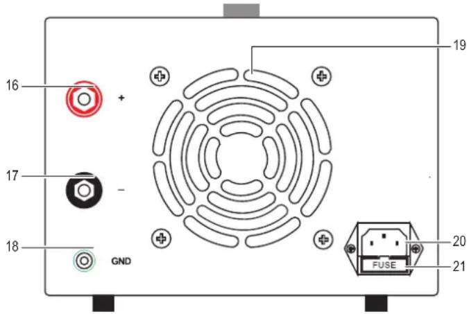
Operating elements
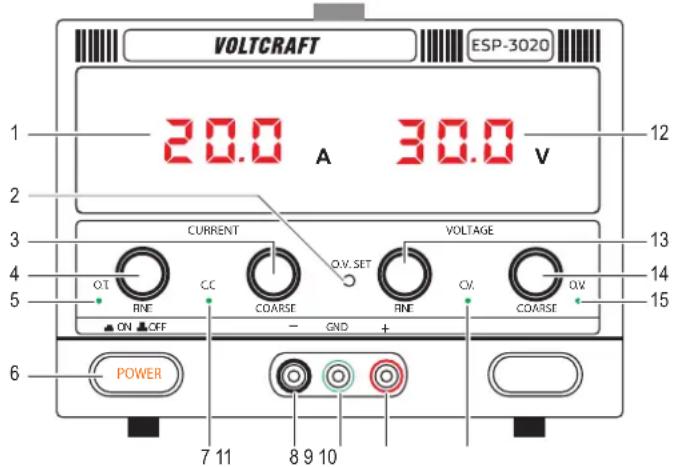
a) Front panel
1 Output current indicator
Shows the output current measured at the output terminals
2 O.V. SET: Over voltage potentiometer
3 COARSE (current) regulator
4 FINE (current) regulator
5 OT: Over temperature indicator
6 POWER (ON/OFF) button
7 C.C.: Constant current mode indicator
Lights up in constant current mode
8 - (black): Negative output terminal
9 GND (green): Chassis ground output terminal
10 + (red): Positive output terminal
11 C.V.: Constant Voltage mode indicator. Lights up in constant voltage mode
12 Output voltage indicator
Shows the output voltage measured at the output terminals
13 FINE (voltage) regulator
14 COARSE (voltage) regulator
15 O.V.: Over voltage indicator
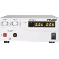
b) Back panel

Use the output terminals located on the back panel if the connected load current exceeds 10 A.
16 + (red): Positive output terminal
17 - (black): Negative output terminal
18 GND (green): Chassis ground output terminal
19 Air outlet
20 Power supply socket
21 FUSE: Fuse holder
Setting up
- Place the lab power supply on an sturdy and even surface.
- Make sure the POWER button is in the OFF position.
- Connect the power cord to a suitable power supply.
Connecting loads

Important
- Switch connected loads and the lab power supply OFF before disconnecting and connecting.
-
The total power of all connected loads should not exceed the maximum power output of the lab power supply.
-
Switch the power OFF.
- Set the voltage and current supply dials to minimum.
- Connect the positive output terminal (+) and negative output terminal (-) with a load or similar component. Use the dedicated ground connection (GND) to earth the load.
- Use adequately dimensioned cables with 4 mm banana plugs or standardized lab cables.
- The socket heads can be screwed on to attach cable strands using screw terminals.

If the connected load current exceeds 10 A, use the output terminals located on the back panel.
Operation

Important
- If running inductive loads e.g. magnetic coils, DC motors, stepper motors etc., adjust the voltage and current slowly.
- The maximum uninterrupted operating time of the lab power supply is 24 hours. After that the lab power supply should be switched off until it has cooled down to ambient temperature.
This power supply operates as a constant voltage (C.V.) or constant current (C.V.) source. Automatic crossover to either mode of operation occurs when the load condition changes.
a) Constant voltage (C.V.)
The constant voltage source (C.V.) will be active if the load current is less than the preset current limit value. Use the voltage regulator controls the set the output voltage.
To set the output voltage:
- Turn the voltage regulators anti-clockwise to minimum and the current regulators clockwise to maximum.
- Switch the power ON. The C.V. indicator will light in constant voltage mode.
- Slowly increase the voltage until you reach the desired output voltage. The output voltage indicator will show the output voltage at the terminals.
- Switch the power OFF.

Before connecting a load, make sure the set voltage is less than the rated voltage of the load or electronic components.
b) Constant current (C.C.)

Important
Read section "d) Connecting loads" before attempting to set any current limits. You have to switch on a connected load and the lab power supply to be able to set the exact current limit.
- The C.V. must first be set before setting the C.C. See section "Constant voltage (C.V.)"
- During C.C setting, do not rotate the voltage dial when the C.V value has been set.
When the load current is ≥ preset current limit, the power supply will cross over to constant current mode. The voltage will drop, the “C.C.” mode indicator will light up, and the power supply will operate as a constant current source.
When the load current drops below the preset current limit, the supply will return to constant voltage (C.V.) mode.
Setting the output current:
- Switch the power ON.
- Connect the positive output terminal (+) and negative output terminal (-) with a load.
- Slowly increase the current until you reach the desired output current.
c) Setting the current limit

Important
- Read section "Connecting loads" before attempting to set any current limits.
- You need to switch a connected load and the lab power supply on to be able to set the exact current limit.
- You can only read the current limit value during operation.
-
First adjust the permissible operating voltage of the connected load using the two voltage controls.
-
Set C.C (fine): this control knob should be in the mid-position.
- Set C.C (coarse): adjust the output current limit to the approximate desired current.
- The current value increases when the knob is rotated clockwise and decreases when the knob is rotated counter-clockwise.

If both voltage adjustment knobs are turned all the way counter-clockwise, the voltage display shows "00.0" volts.
The lab power supply is in the current-controlled state if both output current limit knobs are turned all the way to the left.
d) Mechanical over voltage limit (O.V. SET)
This is a mechanical setting via potentiometer and will be fixed until a new value has been set:
- Range: 1.5 - 35 V
- Default: 33.5 V
-
Set C.C (coarse/fine) to min. (0 A)
-
Set C.V. (coarse/fine) to min. (0 V)
-
Turn power ON.
-
Slowly increase C.C. coarse dial until the C.V. mode indicator lights up.
-
Adjust C.V. (coarse/fine) to set a voltage.
-
Use a small flathead screwdriver to rotate the O.V. potentiometer (O.V. SET) all the way anti-clockwise until the O.V. (over voltage indicator triggers)
- The voltage supply will cut off when the working voltage of the load is greater than the set value. The power supply voltage will drop to 0 - 0.5 V (no output).
-
Switch the lab power supply OFF.
-
Lower the C.V. setting.
-
Switch the lab power supply ON.
If the mechanical over voltage limit (O.V. SET) is triggered:
-
Repeat steps 7 -9 to start working again.
-
Repeat steps 1 - 9 to set a new value.
Protection mechanisms

Important
Safety mechanisms are integrated into the product. If a protection mechanism is triggered, switch the power OFF immediately!
If a protection mechanism is triggered, the power supply voltage will drop to 0 - 0.5 V (no output)
- Switch the power OFF immediately.
- Remove the condition(s) triggering the protection mechanism. Allow the product to completely cool down if needed.
- Switch the power back ON.
| Protection Description | |
| Overload Working current of load > than set value. | |
| Over-current | Protection against excessive currents or current beyond the acceptable current rating of the lab power supply. |
| Short circuit | The lab power supply has a protection circuit which will limit the current in the event of a short circuit. |
| Over-temperature | O.T. indicator lights up when the inner temperature of power supply reaches to 75 °C. |
| Over-voltage Working voltage of load > greater than set value. | |
Troubleshooting
| Problem Suggestions | |
| Power supply does not work/display is blank. | Check the power switch is ON.Check the power cable connectionCheck that the proper mains voltage is applied.Check if the fuse has blown fuse. See “Replacing the fuse”.Protection mechanism has been triggered. See section “Protection mechanisms”. |
| Connected loads do not work. | Check polarity of the connection sockets.Check if the current limit is set.Reduce the lab power supply load by removing a load.Check the specifications of the loads.Protection mechanism has been triggered. See section “Protection mechanisms”. |
| Power is cut off before the coarse voltage is ≥32 V | If the O.V. SET potentiometer has been adjusted it, it may have been set too low. See section “Operation, d) Mechanical over voltage limit (O.V. SET)” for further information. |
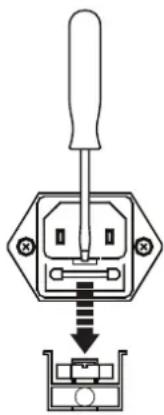
Replacing the fuse

Important
Never use a fuse with other specifications. Never bridge a defective fuse! This may cause a fire or a fatal electric shock!
- Switch off the product first, then disconnect all cables!
- Remove the cover over the fuse holder located at the back of the main unit.
- Use a blunt object such as a flat head screwdriver to gently pry the fuse out.
- Perform a continuity test on the fuse, e.g. with an appropriate meter (digital multimeter).
- If the fuse is defective, replace it with a new fuse of the same type. See section "Technical data" for information about the fuse type. Insert a replacement fuse until it clicks into place, then replace the protective cover.
- Connect the power supply to the mains and switch it back on.

If the fuse blows again, disconnect the workstation from the mains and ask a technician to conduct a thorough inspection.
natural_image
Diagram of a screwdriver inserted into an electrical socket (no text or symbols)Care and cleaning

Do not use any aggressive cleaning agents, rubbing alcohol or other chemical solutions as they can cause damage to the housing and malfunctioning.
- Disconnect the product from the mains socket and disconnect all connected devices before you start cleaning it.
- The product requires no maintenance; Do not take it apart.
- Clean the product with a dry, fibre-free cloth.
Disposal

This symbol must appear on any electrical and electronic equipment placed on the EU market. This symbol indicates that this device should not be disposed of as unsorted municipal waste at the end of its service life.
Owners of WEEE (Waste from Electrical and Electronic Equipment) shall dispose of it separately from unsorted municipal waste. Spent batteries and accumulators, which are not enclosed by the WEEE, as well as lamps that can be removed from the WEEE in a non-destructive manner, must be removed by end users from the WEEE in a non-destructive manner before it is handed over to a collection point.
Distributors of electrical and electronic equipment are legally obliged to provide free take-back of waste. Conrad provides the following return options free of charge (more details on our website):
• in our Conrad offices
• at the Conrad collection points
- at the collection points of public waste management authorities or the collection points set up by manufacturers or distributors within the meaning of the ElektroG
End users are responsible for deleting personal data from the WEEE to be disposed of.
It should be noted that different obligations about the return or recycling of WEEE may apply in countries outside of Germany.
Technical data
a) Product
Rated input 200 - 240 V/AC 50 - 60 Hz, 4.5 A
Output voltage range.... 0 - 30 V/DC (variable)
Output current range 0 - 20 A (variable)
O.V. Set (potentiometer)....5 - 35 V/DC, 33.5 V/DC (factory setting)
Power output .... max. 600 W
Display accuracy .... ±0,5% ±1 digits
Operating time....max. 24 h (uninterrupted)
Fuse.....F10 A, 250 V/AC
Protection class ....I
Power cord length....1.5 m
Protection ........ overload, over-current, short-circuit, over-temperature, over-voltage.
Operating temperature/humidity...0 to +40 °C, ≤80% RH
Storage temperature/humidity ..... -10 to +70 °C, ≤70% RH
Dimensions (L x W x H)....320 x 200 x 152 mm
Weight 2.9 kg
b) Output voltage
No-load....≤0.5% ±100 mV
Load....≤1 %
Residual ripple....≤200 mVp-p
c) Output current
No-load....≤0.5% ±100 mA
Load.... ≤1 %
Residual ripple....≤200 mAp-p
F Mode d'emploi
a) Tension continue (C.V.)
natural_image
Diagram of a screwdriver inserted into an electrical socket, showing internal components and wiring (no text or symbols)natural_image
Diagram of a screwdriver inserted into an electrical socket, showing internal components and wiring (no text or symbols)
- Entsorgung
- ESP-3020 Laboratory Power Supply
- Intended use
- Delivery content
- Up-to-date operating instructions
- Explanation of symbols
- Safety instructions
- General information
- a) Connected devices
- b) Electrical
- - CAUTION!
- c) Product
- d) Fuse
- Operating elements
- a) Front panel
- b) Back panel
- Setting up
- Connecting loads
- Important
- Operation
- a) Constant voltage (C.V.)
- b) Constant current (C.C.)
- c) Setting the current limit
- d) Mechanical over voltage limit (O.V. SET)
- If the mechanical over voltage limit (O.V. SET) is triggered:
- Protection mechanisms
- Replacing the fuse
- Care and cleaning
- Disposal
- Technical data
- a) Product
- b) Output voltage
- c) Output current
- a) Tension continue (C.V.)
Brand : VOLTCRAFT
Model : ESP-3020
Category : Power bank