SPS 1525 PFC - Power Supply VOLTCRAFT - Free user manual and instructions
Find the device manual for free SPS 1525 PFC VOLTCRAFT in PDF.


User questions about SPS 1525 PFC VOLTCRAFT
0 question about this device. Answer the ones you know or ask your own.
Ask a new question about this device
Download the instructions for your Power Supply in PDF format for free! Find your manual SPS 1525 PFC - VOLTCRAFT and take your electronic device back in hand. On this page are published all the documents necessary for the use of your device. SPS 1525 PFC by VOLTCRAFT.
USER MANUAL SPS 1525 PFC VOLTCRAFT
Variable Switched-Mode Mains
Power Supply with PFC
Item No. 511568 (SPS 1525 PFC)/
511569 (SPS 1540 PFC)/511570 (SPS 1560 PFC) Page 14 - 25
F Mode d'emploi
- Introduction 15
- Explanation of symbols 15
- Intended use 16
- Delivery content 16
- Features and functions 17
- Safety instructions 17
a) General information 17
b) Connected devices 18
- Operating elements 19
- Operation 20
a) Connecting the power cable. 20
b) Setting the desired output voltage 20
c) Setting the fixed voltage of 13.8V (only SPS 1525/1540 PFC) 20
d) Connecting a consumer 21
e) "SENSE" function (only SPS 1560 PFC). 21
f) REMOTE control (only SPS 1560 PFC) 22
g) Replacing the fuse 24
- Troubleshooting 24
- Care and cleaning 25
- Disposal 25
- Technical data 25
1. Introduction
Dear customer,
Thank you for purchasing this product.
This product complies with the statutory national and European requirements.
To maintain this status and to ensure safe operation, you as the user must observe these operating instructions!

These operating instructions are part of this product. They contain important notes on commissioning and handling. Also consider this if you pass on the product to any third party. Therefore, retain these operating instructions for reference!
If there are any technical questions, please contact: www.conrad.com/contact
2. Explanation of symbols

The symbol with the lightning in the triangle is used if there is a risk to your health, e.g. due to an electric shock.

The symbol with the exclamation mark in the triangle is used to indicate important information in these operating instructions. Always read this information carefully.

The arrow symbol indicates special information and advice on operation.
Fuse disconnector, short-circuit proof to a limited extent.

Only to be used in dry indoor areas.

This product has been CE-tested and meets the required European guidelines.
3. Intended use
Connection and operation of extra-low voltage consumers with an operating voltage of 3V - 15V / DC for model SPS 1525/1540 PFC or 1V - 15V for model SPS 1560 PFC to the connecting jacks.
The power consumption of a connected consumer may not exceed 25 A for the SPS1540 model, 40A for the model SPS1540 and 60 A for the 1560 model.
The switched-mode mains power supply is designed in compliance with protection class 1. It is only approved for connection to shockproof sockets with protective grounding and an alternating current of 230V / 50Hz commonly used in households.
Operation is impermissible under unfavourable ambient conditions. The following are unfavourable ambient conditions:
- Moisture or excessive humidity
- Dust and combustible gases, vapours or solvents
- Thunder and lightning or similar conditions such as strong electrostatic fields etc.
It is intended for indoor use only. Do not use it outdoors. Contact with moisture, e.g. in bathrooms, must be avoided under all circumstances.
For safety and approval purposes, you must not rebuild and/or modify this product. If you use the product for purposes other than those described above, the product may be damaged. In addition, improper use can result in short circuits, fires, electric shocks or other hazards. Read the instructions carefully and store them in a safe place. Make this product available to third parties only together with its operating instructions.
All company names and product names are trademarks of their respective owners. All rights reserved.
4. Delivery content
- Variable switched-mode mains power supply with PFC
- Operating instructions
Up-to-date Operating Instructions
Download the latest operating instructions at www.conrad.com/downloads or scan the QR code shown. Follow the instructions on the website.

5. Features and functions
- The SPS 1525 PFC and SPS 1540 PFC mains power supply units use switching network technology with the advantages of weight and size reductions. Switched-mode mains power supply unit use chopped mains voltages and return a broad spectrum of harmonic waves to the mains line, which may cause interference in other devices. To suppress these harmonic waves, a PFC (Power Factor Correction) has been integrated in the product.
- The dc output is dc-isolated and features a fuse disconnector to the mains voltage.
- The output voltage can be adjusted by means of the adjustment control (6) from 3 V to 15 V/DC or for the SPS 1560 from 1V - 15Vm; current limitation is not possible.
- A special feature of the models SPS 1525 PFC und SPS 1540 PFC is a fixed voltage switch on the underside of the device to fix the output voltage to 13.8V / DC .
- The secondary DC connection is effected through two coloured connection jacks.
- For the switched-mode power supply SPS 1560 PFC up to 5A can be collected at the front side and up to 60A at the rear.
- The mains power supply is cooled via a temperature-controlled fan. For this reason, make sure there is an adequate air circulation and lateral distance to obstacles.
- The mains power supply is equipped with an overload protection circuit. This circuit is activated when the maximum permissible current is exceeded due to an overload or short circuit. The red indicator is the overload indicator. If it lights up, the consumer must be disconnected from the mains power supply to avoid damage to the switched-mode mains power supply.
6. Safety instructions

Read the operating instructions carefully and especially observe the safety information. If you do not follow the safety instructions and information on proper handling in this manual, we assume no liability for any resulting personal injury or damage to property. Such cases will invalidate the warranty/guarantee.
a) General information
- The device is not a toy. Keep it out of the reach of children and pets.
- Do not leave packaging material lying around carelessly. This may become dangerous playing material for children.
- Protect the appliance from extreme temperatures, direct sunlight, strong jolts, high humidity, moisture, flammable gases, steam and solvents.
- Do not place the product under any mechanical stress.
-
If it is no longer possible to operate the product safely, take it out of operation and protect it from any accidental use. Safe operation can no longer be guaranteed if the product:
-
is visibly damaged,
-
is no longer working properly,
-
has been stored for extended periods in poor ambient conditions or
-
has been subjected to any serious transport-related stresses.
-
Please handle the product carefully. Jolts, impacts or a fall even from a low height can damage the product.
- On commercial premises, the accident prevention regulations for electrical facilities and equipment of the relevant professional association must be complied with.
- In schools and training centres as well as at hobby and DIY workshops, the use of power packs must be supervised by adequately trained personnel in a responsible manner.
- Please make sure by all means that your hands, your shoes, your clothing, the floor and the power pack are dry.
Live components may be exposed when covers are opened or components are removed, except if this can be done by hand. - Before opening it, disconnect the device from all voltage sources.
- Capacitors in the device may still be charged, even if the device has been disconnected from all voltage sources.
- Do not switch the switched-mode mains power supply on immediately after it has been taken from a cold to a warm environment. Under adverse conditions, the resulting condensation could destroy the device. Allow the device to reach room temperature before switching it on.
- The switched-mode mains power supply generates heat during operation. Make sure it is adequately ventilated. Do not cover the ventilation apertures of the device!
- Do not leave mains power supplies and the connected consumers in operation unattended.
- Exclusively use fuses of the type and rated current specified. It is absolutely impermissible to use repaired fuses.
- Avoid the use of uninsulated metallic cables.
- It is impermissible to connect multiple switched-mode mains power supply units in series or in parallel.
- Power supply units are not designed for application to human beings or animals.
- Consult an expert when in doubt about the operation, safety or connection of the appliance.
- Maintenance, modifications and repairs must only be completed by a technician or an authorised repair centre.
- If you have questions which remain unanswered by these operating instructions, contact our technical support service or other technical personnel.
b) Connected devices
- Also observe the safety and operating instructions of any other devices which are connected to the product.
7. Operating elements
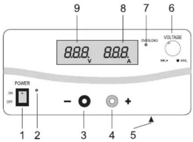
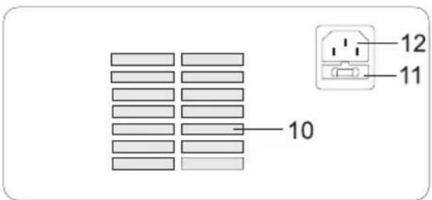
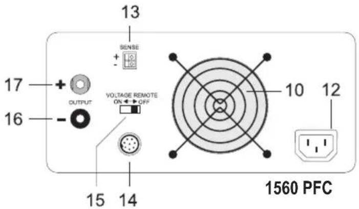
1525 PFC / 1540 PFC
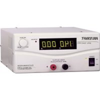
1 Power switch for taking the device into operation (ON / OFF)
2 Power indicator, lights up in green
3 Connecting jack "minus pole" (for 1560 PFC only up to a maximum of 5A)
4 Connecting jack "plus pole" (for 1560 PFC only up to a maximum of 5A)
5 Fixed voltage switch for 13.8V on the underside of the device (only for the 1525 PFC and 1540 PFC)
6 Adjustment control for the output voltage
7 Overload indicator, lights up in red
8 3 digit LED display for output current
9 3 digit LED display for output voltage
10 Fan opening for cooling the device
11 Fuse holder for the mains fuse
12 Shockproof cold device connector
13 "SENSE" connection for automatic voltage correction on the high-current output (16 and 17)
14 Remote control input for voltage control ("VOLTAGE REMOTE")
15 Function switch for remote control
16 Screw terminal jack high-current output "minus pole" up to 60A
17 Screw terminal jack high-current output "plus pole" up to 60A
8. Operation

The switched-mode mains power supply unit is not a charger. To charge batteries, use suitable chargers with a charging current cut-off.
a) Connecting the power cable
- Connect the provided shockproof power cable to the power connector (12, female) of the mains power supply. Make sure it is plugged properly.
- Connect the power cable to a shockproof mains socket with protective grounding.
b) Setting the desired output voltage
- Make sure that there are no consumers connected to the mains power supply.
- Switch on the mains power supply at the power switch (1). The power indicator (2) should light up.
- Now use the DC control (6) to set the desired output voltage. The setting can be checked on the display (9).
c) Setting the fixed voltage of 13.8V (only SPS 1525/1540 PFC)
- Make sure that there are no consumers connected to the mains power supply.
- Switch on the mains power supply at the power switch (1).
- Now set the wiper switch (5) underneath the device to the "FIXED 13.8V " position.
- The output voltage has now been fixed to this values and cannot be changed via the control on the front of the device. The voltage is shown on the display (9).
- To deactivate the fixed voltage, slide the wiper switch to the opposite direction.

Only change the setting when no consumers are connected! Verify the operating voltages of the consumers first!
d) Connecting a consumer
- Make sure the consumer is switched off.
- Verify that the correct output voltage has been set.
- Connect the plus pole (+) of the consumer to the red terminal screw connector "+" (4), and the minus pole (-) of the consumer to the black terminal screw connector "-" (3).
- 4-mm standard connectors can be used for connection but should take place via 20A by means of screw terminals. (the jack heads can be screwed on to the front only for the SPS 1525/1540 PFC!).
- For the switch power unit SPS 1560 PFC up to 5A can be connected at the front safety-jack consumer (automatic current limit) and up to 60A at the rear through high-current terminal jacks.
- The power consumption of the connected consumers is shown on the current display (8).

Make sure that the consumers are switched off when connected to the switched-mode mains power supply. Sparks may be generated when a consumer which has been switched on is connected to the jacks. This may damage the terminal screw connectors as well as the connected cables.
e) "SENSE" function (only SPS 1560 PFC)
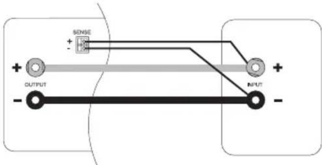
The switched-mode power supply possesses an automatic voltage control for the high-current output. For this, two separate measuring cables are connected parallel to the connecting cables. The potential drop which occurs on the connecting cables is measured on these two measuring cables. The switched-mode power supply compensates this potential drop automatically so that the actually set voltage is pending on the consumer.
Proceed as follows for connection:
- Always connect the supply cables from the power unit to the consumer. Pay attention to correct polarity.
- Press the orange-coloured terminal on the SENSE connection inwards with a small screwdriver and insert the cables into the green terminal openings. Check that they are plugged firmly.
- Now connect the two "SENSE" cables to the consumer observing the correct polarity. The conductor cross-section for the "SENSE" cables must be at least 22AWG (= 0.34mm^2) .
- Always slacken the connection in the reverse order (first of all the "SENSE" cables and then the connecting cables).

- Make sure that you contact the SENSE cables as close as possible to the connecting point of the consumer.
- Short the "SENSE" cables.
f) REMOTE control (only SPS 1560 PFC)
Through the built-in "REMOTE" control connection, the voltage setting can take place with an external voltage source or through an externally adjustable resistance (short "poti") and it's possible to switch the DC output on/off.
The REMOTE connection takes place on the rear REMOTE built-in plug (14).
Preparation of the remote control connection.
- Turn the central screw of the supplied slide-in jack and remove the front, black contact jack by means of a small turning movement.
- Draw the five connecting cables with a conductor cross-section of at least 22AWG (=0,34mm^2) through the metal sleeve from the rear. Solder these five cables firmly and carefully to the soldering lugs no.1,2,3,7 and 8 of the black contact jacks.
- Mark the loose ends of the cables with the corresponding contact numbers (1-3) to rule out any confusion.
- Insert the black contact jack in the reverse order into the metal sleeve and screw these firmly.
Control through external voltage source
The power unit can be remote-controlled by means of an external voltage source of 0 to 5V/DC over the complete output voltage range.
Proceed as follows for connection:
-
Connect the connecting cable of the REMOTE plug as illustrated.
-
Connection 2 to the plus pole (+) of the voltage supply and connection 3 to the minus pole (+) of the voltage supply
- Connection 1 is not required.
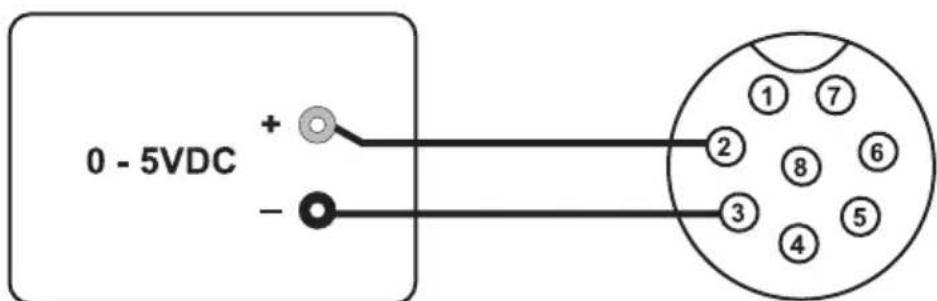

The voltage on the remote control connection may not exceed 5V.
nnections may not be shorted.
- Switch off the switched-mode power supply and then connect the REMOTE plug to the rear remote connection. Screw down the external fastening ring.
Turn the voltage of the external voltage source to zero.
- Slide the rear VOLTAGE REMOTE switch to the "ON" position.

- Switch the switched-mode power supply on. The desired output voltage can now be set through the external voltage source. Control the complete adjustment area for correct function.
- If this remote control function is no longer required, the switch to the "OFF" position.
Control through a controllable resistance (poti)
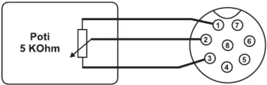
The power unit can be remote-controlled by means of an external poti of 5 KOhm over the complete output voltage range.
Proceed as follows for connection:
-
Connect the connecting cable of the REMOTE plug as illustrated.
-
Connection 1 at one end of the resistance.
- Connection 2 at the centre sliding contact of the resistance.
- Connection 3 at the second end of the resistance.
-
Switch off the switched-mode power supply and then connect the REMOTE plug to the rear remote connection. Screw the external fastening ring.
-
Slide the rear VOLTAGE REMOTE switch to the "ON" position.

- Switch the switched-mode power supply on. The desired output voltage can now be set through the external poti. Control the complete adjustment area for correct function.
- If this remote control function is no longer desired, move the switch to the "OFF" position
Enable and disable the output
You can use Port 7 and 8 to remote control the output on/off.
- Open Port 7 and 8 if you want to enable the output (default).
- Short Port 7 and 8 if you want to disable the output.
g) Replacing the fuse
If it is no longer possible to switch on the mains power supply, the mains fuse has probably tripped.
Proceed as follows to replace the mains fuse:
- Switch off the mains power supply and remove all the connection and power cables.
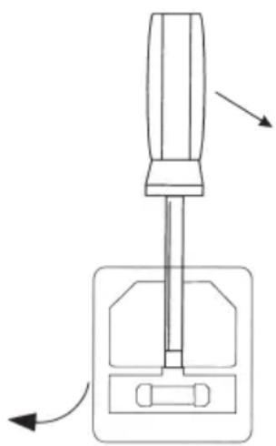
- Use a suitable screwdriver for slotted screws to prise out the fuse holder on the rear of the device.
- Replace the defective fuse with a new fine-wire fuse (5 × 20 ~mm) of the same type and rated current, which is as follows: F 3.15 A / 250 V (fast blowing).
- Press the fuse-link back into the fuse holder until it snaps in properly.
9. Troubleshooting
By purchasing the switched-mode mains power supply you have acquired a product that is reliable and operationally safe. However, problems and malfunctions may occur. For this reason we want to describe how to troubleshoot potential malfunctions:

Always heed the safety instructions!
Other repair work must always be carried out by qualified experts familiar with the hazards involved and with the relevant regulations. Unauthorized modifications and repairs of or inside the device lead to expiry of the warranty.
| Malfunction Possible cause | |
| The mains power supply does not work | Is the green power indicator (2) of the mains power supply lit?Check the mains voltage (you may also want to check the mains fuse in the device or the line circuit breaker). |
| Connected consumers do not work | Correct voltage set?Correct polarity?Overload of the mains power supply (display 7)?Check the technical data of the consumers. |
| The output voltage of 13.8 V cannot be changed | The mains power supply has been switched to the fixed voltage mode.Changethe position of the fixed voltage switch underneath the device. |
Periodically check the technical safety of the device, e.g. check for damage to the housing etc.
10. Care and cleaning

Do not use any aggressive cleaning agents, rubbing alcohol or other chemical solutions as they can cause damage to the housing and malfunctioning.
- Disconnect the product from the mains before each cleaning.
- The switched-mode mains power supply units are maintenance-free, apart from the need to replace fuses and cleaning them once in a while. Use a clean, lint-free, antistatic and dry cloth to clean the device.
11. Disposal
Product

Electronic devices are recyclable waste and must not be disposed of in the household waste. At the end of its service life, dispose of the product in accordance with applicable regulatory guidelines.
Thus fulfill your statutory obligations and contribute to the protection of the environment.
12. Technical data
| SPS 1525 PFC SPS 1540 | PFC SPS 1560 PFC | ||
| Operating voltage 230 V~ / 50 Hz | |||
| Power consumption max. | 460 VA max. 782 VA max. | 1058 VA | |
| Output 3-15 V/DC voltage (variable) or fixed voltage of 13.8 V 1-15 V/DC controllable | |||
| Output current | 25 A | 40 A | 5 A front; 60 A rear |
| Residual ripple | 10 mVrms (rms=effective) | max. 40 mVp-p | |
| Control response at Change of mains supply +/- 10%: | 80 mV | 0.05%+ 3mV | |
| Change of load 0~100%: | 230 mV | 0.1% + 5mV | |
| Mains fuse | 3.15 A / 250 V (fast blowing) | 5 A /250 V (fast blowing) | |
| Operating temperature | + 0 °C to + 40 °C | ||
| Rel. humidity | max. 85 (non-condensing) | ||
| Dimensions (W x H x D) | 220 x 110 x 240 mm | 220 x 110 x 310 mm | 220 x 110 x 360 mm |
| Weight | approx. 2.6 kg approx. 3.5 kg | approx. 5.8 kg | |
Table des matieres
Page
Chere cliente, cher client,
France (email): technique@conrad-france.fr
This is a publication by Conrad Electronic SE, Klaus-Conrad-Str. 1, D-92240 Hirschau (www.conrad.com).
All rights including translation reserved. Reproduction by any method, e.g. photocopy, microfilming, or the capture in electronic data processing systems require the prior written approval by the editor. Reprinting, also in part, is prohibited. This publication represent the technical status at the time of printing.
Copyright 2021 by Conrad Electronic SE.
Copyright 2021 by Conrad Electronic SE.
Copyright 2021 by Conrad Electronic SE.