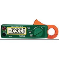
380942 - Multimeter Extech - Free user manual and instructions
Find the device manual for free 380942 Extech in PDF.


User questions about 380942 Extech
0 question about this device. Answer the ones you know or ask your own.
Ask a new question about this device
Download the instructions for your Multimeter in PDF format for free! Find your manual 380942 - Extech and take your electronic device back in hand. On this page are published all the documents necessary for the use of your device. 380942 by Extech.
USER MANUAL 380942 Extech
Congratulations on your purchase of the Extech Model 380942 DC/AC Clamp Meter. This meter is shipped fully tested and calibrated and, with proper use, will provide years of reliable service.
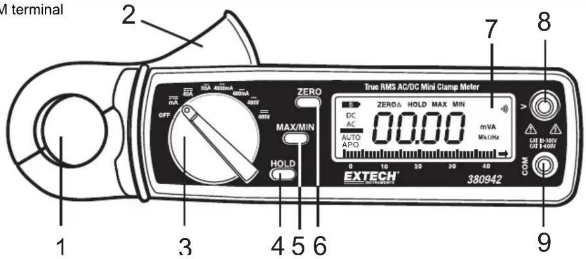
Meter Description
- Current sense jaw
- Measurement Trigger
- Function switch
- Data HOLD key
- MAX / MIN key
- One-touch DCA ZERO key
- LCD Display
- Positive input terminal for Voltage
- COM terminal
text_image
M terminal 1 2 3 4 5 6 7 8 9 EXTECH® 380942 True RMS AC/DC Mini Clamp Meter ZERO MAX/MIN HOLD OK OFF 30A 400mA 400mA 400V 400V 0.00 mVA MkΩHz 0 10 20 30 40 COM CUT 11-30V CUT 14-40VSafety Symbols and Information

Caution! Risk of danger. Refer to accompanying documents.

Caution! Risk of electric shock

Earth (Ground)
This meter has been designed to be safe in use, but the operator must use caution in its operation. The rules listed below should be carefully followed for safe operation.
- NEVER apply voltage or current to the meter that exceeds the specified maximum:
- USE EXTREME CAUTION when working with high voltages.
- DO NOT measure voltage if the voltage on the "COM" input jack exceeds 600V above earth ground.
- ALWAYS turn off the power and disconnect the test leads before opening the back to replace the fuse or batteries.
- NEVER operate the meter unless the back cover and the battery/fuse door are in place and fastened securely.
AC Current Measurements (True RMS)
WARNING: To avoid electric shock, disconnect the test leads from the meter before making current measurements.
1) Set the Function switch to the 400mA, 4000mA, or 30A AC range.
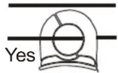
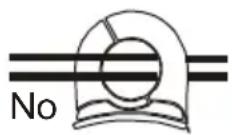
2) Press the jaw trigger and clamp around, fully enclosing a single conductor. Do not allow a gap between the two halves of the jaw. Refer to the diagram at right for the correct way to enclose a single conductor.
3) Read the AC Current value on the LCD's digital or bargraph display.
DC Current Measurements
WARNING: To avoid electric shock, disconnect the test leads from the meter before making current measurements.
1) Set the Function switch to the mA or 40A DC range.
2) Press the DCA zero key to null the meter display.
3) Press the Trigger to open the current sense Jaw.
4) Fully enclose the conductor to be measured. Do not allow a gap between the two halves of the jaw.
5) Read the DC Current value on the LCD's digital or bargraph display.
AC Voltage Measurements (True RMS)
WARNING: To avoid electric shock or damage to the meter, do not make any voltage measurements that exceed the maximum specified limits.
1) Set the Function switch to the 400V AC position.
2) Insert the test leads to the meter as follows: Red lead to "V" terminal; Black lead to the COM input.
3) Connect the test leads to the circuit or device under test.
4) Read the AC Voltage value on the LCD's digital or bargraph display.
DC Voltage Measurements
WARNING: To avoid electric shock or damage to the meter, do not make any voltage measurements that exceed the maximum specified limits.
1) Set the Function switch to the 400V DC position.
2) Insert the test leads to the meter as follows: Red lead to "V" terminal; Black lead to the COM input.
3) Connect the test leads to the circuit or device under test.
4) Read the DC Voltage value on the LCD's digital or bargraph display.
Relative Measurements
1) Press the ZERO key. The displayed reading will zero and the word ZERO will appear on the upper portion of the LCD.
2) All subsequent measurements will now be displayed with respect to the zeroed reading. For example, if a 20A reading is zeroed and a 30A reading is subsequently measured, the LCD will display 10A.
3) Press the zero button once more to return to normal operating mode.
4) Note that Relative mode is not available if MIN/MAX mode is enabled.
5) LCD displays relative numerical value without bargraph.
Data Hold
To freeze the current reading on the LCD, press the Data Hold key. The word HOLD will appear on the LCD while the meter is in the Data Hold mode. To release the Data Hold function and return the meter to normal operation, press the Data Hold key again. The word HOLD will switch off.
MIN/MAX Readings
Pressing the MIN/MAX key allows the meter to display ONLY the highest and the lowest readings encountered. Press the MIN/MAX key once to view the minimum reading, press it again to view the maximum reading. The LCD will toggle between the MIN and MAX values. Press and hold MIN/MAX button for more than 2 seconds to return to normal operating mode. Zero function will be disabled when MIN/MAX is enabled.
Auto Power Off
To extend battery life, the meter will auto power off after 15 minutes of operation (APO will be displayed on LCD). To resume operation, either turn the meter OFF for 3 seconds and then ON again, or press the HOLD button. Pressing any button or turning the rotary switch will reset the 15 minute timer. To disable the auto power off function, press down the "HOLD" key while turning the meter on.
Maintenance
Battery Replacement
1) When the low battery symbol appears on the LCD the batteries must be replaced.
2) Turn the meter OFF and remove the rear battery compartment Phillips screw.
3) Lift off the battery compartment cover and replace the two 1.5V AA batteries.
4) Replace the compartment cover and secure the screw.
Cleaning
Caution: Use only a dry cloth to clean the plastic case.
General Specifications
Display 3-3/4 digit (4032 count) LCD with 40 segment bargraph
Functions ACA, DCA, ACV, DCV
Polarity Minus sign (-) indicates negative polarity
Current sensor Hall effect sensor type
Overload indication OL
DCA zero adjust One touch zero key
Display rate 3 readings/second (30 readings/second for bargraph)
Battery Two 1.5V AA batteries
Operating conditions 4 ^ F to 122 ^ F (-10 ^ C to 50 ^ C); < 85% Relative Humidity
Storage conditions - 4 °F to 140°F (-20°C to 60°C); < 75% Relative Humidity
Altitude Operate at less than 2000 meters (for indoor use only)
Power consumption Approximately 15mA DC
Weight 6.2 oz. (190g) including battery
Dimensions 7.2 x 2.5 x 1.4" (183 x 63.6 x 35.6mm) (H x W x D)
Jaw opening 0.9" (23mm)
Standards IEC 1010 Category III 300V, Category II 600V
Range Specifications (23°C±5°C)
| Function | Range | Resolution | Accuracy (of reading) | Overload protect | |
| DC Current | 4000mA | 1mA | ±(2.0% + 3d) | 40A DC | |
| 30A | 10mA | 100A DC | |||
| 40A | 10mA | ±(2.5% + 3d) | 100A DC | ||
| AC Current(True RMS) | 50/60Hz | 40 to 100Hz | |||
| 400mA | 0.1mA | ±(1.5% + 5d) | ±(2.0% + 5d) | 40A AC | |
| 50/60Hz | 40 to 1kHz | ||||
| 4000mA | 1mA | ±(2.5% + 5d) | ±(3.0% + 5d) | 40A AC | |
| 30A | 10mA | ±(2.0% + 5d) | ±(2.5% + 5d) | 100A AC | |
| DC Voltage | 400V | 0.1V | ±(1.0% + 2d) | 1000V DC | |
| AC Voltage(True RMS) | 50/60Hz | 40 to 1kHz | |||
| 400V | 0.1V | ±(1.5% + 4d) | ±(2.0% + 5d) | 800V AC | |
Specification Notes
• AC Voltage and Current Crest Factor: < 3
• AC / DC Voltage Input Impedance: 10MΩ
Warranty
FLIR Systems, Inc. warrants this Extech Instruments brand device to be free of defects in parts and workmanship for one year from date of shipment (a six month limited warranty applies to sensors and cables). If it should become necessary to return the instrument for service during or beyond the warranty period, contact the Customer Service Department for authorization. Visit the website www.extech.com for contact information. A Return Authorization (RA) number must be issued before any product is returned. The sender is responsible for shipping charges, freight, insurance and proper packaging to prevent damage in transit. This warranty does not apply to defects resulting from action of the user such as misuse, improper wiring, operation outside of specification, improper maintenance or repair, or unauthorized modification. FLIR Systems, Inc. specifically disclaims any implied warranties or merchantability or fitness for a specific purpose and will not be liable for any direct, indirect, incidental or consequential damages. FLIR's total liability is limited to repair or replacement of the product. The warranty set forth above is inclusive and no other warranty, whether written or oral, is expressed or implied.
Calibration, Repair, and Customer Care Services
FLIR Systems, Inc. offers repair and calibration services for the Extech Instruments products we sell. NIST certification for most products is also provided. Call the Customer Service Department for information on calibration services available for this product. Annual calibrations should be performed to verify meter performance and accuracy. Technical support and general customer service is also provided, refer to the contact information provided below.
Support Lines: U.S. (877) 439-8324; International: +1 (603) 324-7800
Technical Support: Option 3; E-mail: support@extech.com
Repair & Returns: Option 4; E-mail: repair@extech.com
Product specifications are subject to change without notice
Please visit our website for the most up-to-date information
www.extech.com
FLIR Commercial Systems, Inc., 9 Townsend West, Nashua, NH 03063 USA
ISO 9001 Certified
Copyright © 2014 FLIR Systems, Inc.
All rights reserved including the right of reproduction in whole or in part in any form
www.extech.com
Garantie
Copyright © 2014 FLIR Systems, Inc.
Copyright © 2014 FLIR Systems, Inc.
