
PRC20 - Measurement Extech - Free user manual and instructions
Find the device manual for free PRC20 Extech in PDF.


| Type de produit | Digital Multimeter |
| Marque | Extech |
| Modèle | PRC20 |
| Dimensions | Approximately 7.0 x 3.5 x 1.5 inches (180 x 90 x 38 mm) |
| Poids | Approximately 12 oz (340 g) including batteries |
| Alimentation | Two AAA batteries (1.5V each) |
| Affichage | LCD, 4000 counts |
| Fonctions principales | AC/DC voltage, DC current, resistance, diode test, continuity, capacitance, frequency |
| Plage de tension AC | 400 mV to 600 V |
| Plage de tension DC | 400 mV to 600 V |
| Plage de courant DC | 400 µA to 10 A |
| Plage de résistance | 400 Ω to 40 MΩ |
| Plage de capacité | 4 nF to 200 µF |
| Plage de fréquence | 10 Hz to 100 kHz |
| Entretien et nettoyage | Wipe with a damp cloth; do not use solvents; store in a dry place |
| Sécurité | CAT II 600V, double insulation, overvoltage protection |
| Pièces détachées et réparabilité | Replaceable batteries and fuse; no user-serviceable parts inside; contact Extech support |
| Informations générales | Includes test leads, manual, and battery; auto power-off; data hold |
Frequently Asked Questions - PRC20 Extech
User questions about PRC20 Extech
0 question about this device. Answer the ones you know or ask your own.
Ask a new question about this device
Download the instructions for your Measurement in PDF format for free! Find your manual PRC20 - Extech and take your electronic device back in hand. On this page are published all the documents necessary for the use of your device. PRC20 by Extech.
USER MANUAL PRC20 Extech
Thermocouple Calibrator
Model PRC20
Thank you for selecting the Extech Model PRC20. This device is shipped fully tested and calibrated and, with proper use, will provide years of reliable service. Please visit the Extech Instruments website (www.extech.com) to check for the latest version of this User Guide. Extech Instruments is an ISO-9001 certified company.
Safety
International Safety Symbols

This symbol, adjacent to another symbol or terminal, indicates the user must refer to the manual for further information.

This symbol, adjacent to a terminal, indicates that, under normal use, hazardous voltages may be present

Double insulation
Safety Notes
- Turn the unit OFF when the device is not in use.
- Remove the batteries if the device is to be stored for longer than 60 days.
• Never dispose of batteries in a fire. Batteries may explode or leak. - Never mix battery types. Always install new batteries of the same type.
Cautions
- Improper use of this meter can cause damage, shock, injury or death. Read and understand this user manual before operating the meter.
- Inspect the condition of the thermocouples and the meter itself for any damage before operating the meter. Repair or replace any damage before use.
-
If the equipment is used in a manner not specified by the manufacturer, the protection provided by the equipment may be impaired.
-
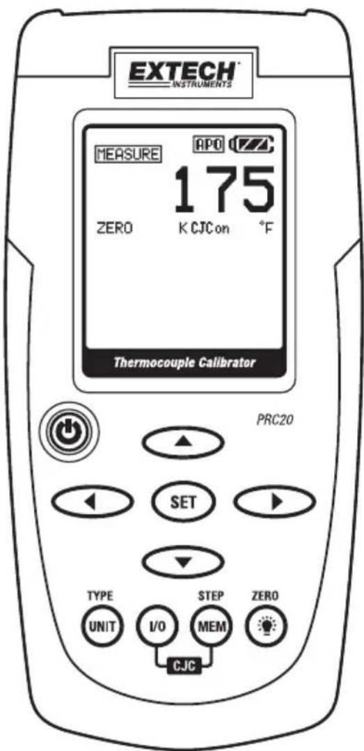
AC adaptor input jack
- Display
- Power ON/OFF
- Source output adjustment arrow buttons
- Set and exit the adjustment mode button
- Unit button (thermocouple type, °F or °C)
- I/O button
- MEM (memory STEP button)
- Backlight/ZERO button
- Thermocouple mini-connector

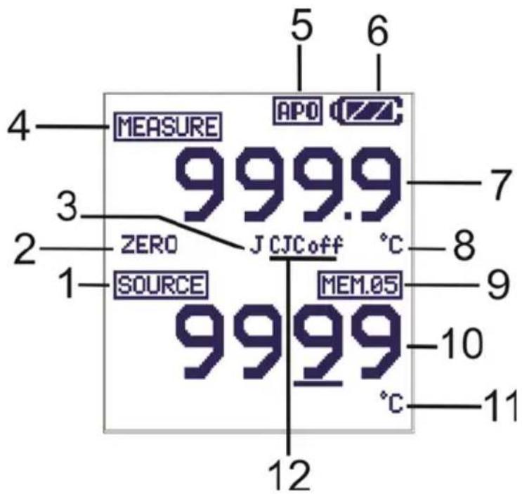
Display Layout
- SOURCE mode icon
- ZERO function status icon
- Thermocouple type
- MEASURE mode icon
- Auto Power OFF active icon
- Battery status icon
- Measure mode value
- Measure mode units icon
- Datalogger memory location
- Source mode value
-
Source mode units icon
-
Cold Junction Compensation (CJC) circuit status (ON or OFF)
POWER BUTTON and AUTO POWER OFF FEATURE
- Use the POWER button to turn the unit ON or OFF. When the unit is powered up, a short self-test will ensue after which the display will stabilize.
- When the battery symbol flashes on the display, replace the battery as soon as possible. Low battery power may cause inaccurate readings and erratic meter operation.
- This instrument is equipped with Auto Power OFF which turns the meter off after 10 minutes of inactivity. To override this feature; press and hold the POWER button until the display icon "ATP" turns off.
UNIT BUTTON
Momentarily press the UNIT button to select °F or °C units.
TYPE BUTTON
Press and Hold the TYPE/UNIT button for 1 second to change the thermocouple type (J, K, T, E, C, R, S, N or mV).
I/O BUTTON
Momentarily press the I/O button to select either SOURCE (output) or MEASURE (input).
CJC ON/OFF
Simultaneously press the IO and MEM buttons to turn the CJC (cold junction compensation) on or off. The CJC icon will indicate the status.
Note: CJC should normally be ON.

(Backlight) BUTTON
Momentarily press the Backlight button to turn the backlight on or off.


In the MEASURE or SOURCE mode, Press and Hold the ZERO (💡) button for 1 second to zero the meter.
OFFSET ADJUSTMENT
The offset adjustment can be used to correct any known linearity errors with the thermocouple.
- Select the measure mode and a thermocouple type (J/K/T/E/C/R/S/N).
- Press and Hold the SET button for 1 second to enter the offset adjust mode.
- Press the ▲ or ▼ button to change the offset value.
- Press and Hold the SET button for 1 second to zero the offset value.
- Momentarily press the SET button to save the change and exit the function.
▶◀▼ and ▲ BUTTONS
The arrow buttons are used to set the output value in the SOURCE mode.
- Select the SOURCE mode
- Press the ▶ or ◀ button select a digit for adjustment. The blinking underline curser identifies the digit selected.
- Press the ▼ or ▲ button to adjust the value of the digit. Press and Hold the ▼ or ▲ button to rapidly adjust the value.
SET BUTTON
The SET button is used to manually step through the 5 stored output values.
- Select the SOURCE mode
- Momentarily press the SET button and the value stored in memory location 01 will be sourced. "MEM.01" appears in the display.
- Each press of the SET button will step through the 5 memory locations.
- The arrow buttons can be used to adjust the value in each memory location.
STEP/MEM BUTTON
The STEP/MEM button is used to automatically step through the 5 stored output values. The meter can be set for a single cycle of the stored values or a continuous cycle.
- Select the SOURCE mode
- Press and Hold the STEP/MEM button. "STEPSS" (single cycle) and "STEPSC" (continuous cycle) will alternately appear in the display. Release the button when the desired mode is displayed.
- In single cycle mode the meter will source the current or voltage displayed in MEM01 for 5 seconds. The meter will then advance to MEM02 for 5 seconds. This will continue through MEM05 and then step down through the memory locations. The cycle will end when MEM01 has been reached.
- In the continuous mode the cycle will continue until manually stopped.
- Momentarily press the MEM button to stop the cycle. "END" will briefly appear in the display.
STORING VALUES INTO MEMORY
There are 5 memory locations for each thermocouple type and for mV. The default values stored in these locations are:
| Memory Location | Type J, K, C, R, S, N | Type T | Type E | mV |
| M1 | 0.0°C(32.0°F) | 0.0°C(32.0°F) | 0.0°C(32.0°F) | 0mV |
| M2 | 100.0°C(212.0°F) | 100.0°C(212.0°F) | 100.0°C(212.0°F) | 10.00mV |
| M3 | 500.0°C(932.0°F) | 200.0°C(392.0°F) | 200.0°C(392.0°F) | 25.00mV |
| M4 | 750.0°C(1382.0°F) | 300.0°C(572.0°F), | 500.0°C(932.0°F) | 40.00mV |
| M5 | 1000.0°C(1832.0°F) | 400.0°C(752.0°F) | 750.0°C(1382.0°F) | 50.00mV |
To change the values in memory:
- Select the SOURCE mode
- Press the SET button to select the memory location to be changed.
-
Press the arrow buttons to adjust to the new value
-
Momentarily press the MEM button to store the value. The memory location icon will blink while the value is being stored.
MEASURE (Input) Mode of Operation
- Turn the meter ON.
- "MEASURE" will appear in the display.
- Momentarily press the UNIT button to select °F or °C.
- Press and Hold the UNIT button for 1 second to change the thermocouple type (or mV).
- Connect the thermocouple to the meter.
- Read the measurement on the display.
Note: See the keypad description section to turn CJC on/off.
SOURCE (Output) Mode of Operation
In this mode, the unit can source the equivalent mV value for the temperature and the thermocouple type selected. The values can be output either manually or stepped from memory as described earlier.
- Turn the meter ON
- MEASURE" will appear in the display.
- Momentarily press the UNIT button to select °F or °C.
- Press and Hold the UNIT button for 1 second to change the thermocouple type (or mV).
- Press the "I/O" button to select SOURCE.
-
Connect the Calibration Cable from the meter to the device to be calibrated.
-
Use the row buttons to set the desired output value in the lower display. The upper display indicates the actual temperature or voltage value being sourced. If the upper display does not match the set value, check the batteries or the connections to the device being calibrated.
The rear stand provides two methods for convenience in viewing.
- Pull the bottom portion of the stand out to place the unit on a flat surface for viewing.
- Pull the bottom and top portions of the stand out, and then rotate the stand to allow the unit to be hung.
Battery Replacement
When the battery icon appears on the display, the six AA batteries must be replaced.
The battery compartment is located on the rear of the meter.
- Open the tilt stand, loosen the captive Philips head screw and remove the battery cover.
- Remove and replace the batteries, observing polarity.
- Replace and secure the battery cover.

Never dispose of used batteries or rechargeable batteries in household waste.
As consumers, users are legally required to take used batteries to appropriate collection sites, the retail store where the batteries were purchased, or wherever batteries are sold.
Disposal: Do not dispose of this instrument in household waste. The user is obligated to take end-of-life devices to a designated collection point for the disposal of electrical and electronic equipment
General Specifications
Display Dot matrix LCD
Cold junction compensation 0.03°C per °C (0.02°F per °F)
Thermocouple Standard and Scale NIST 175, ITS-90
Meter Power 6 AA batteries or AC adaptor
Auto Power OFF Meter automatically powers off after 10 minutes of inactivity
Operating Temperature 5°C to 40°C (41°F to 104°F)
Storage Temperature -20°C to 60°C (-4°F to 140°F)
Operating Humidity Max 80% up to 31°C (87°F) decreasing linearly to 50% at 40°C (104°F)
Storage Humidity <80%
Operating Altitude 2000 meters (7000ft) maximum
Dimensions 159 x 80 x 44 mm (6.3 x 3.2 x 1.7")
Weight 225g (8 oz.) without batteries
Range Specifications
| Source and Measure Ranges | Resolution | Accuracy (% of reading) | |
| Type J | -50 to 1000°C (-58 to 1832°F) | 0.1° (measure)1° (source) | ± (0.05% + 1°C /1.8°F) |
| Type K | -50 to 1370°C (-58 to 2498°F) | ||
| Type T | -120 to 400°C (-184 to 752°F) | ||
| Type E | -50 to 750°C (-58 to 1382°F) | ||
| Type C | 0 to 1750°C (32 to 3182°F) | ||
| Type R | 0 to 1750°C (32 to 3182°F) | ||
| Type S | 0 to 1750°C (32 to 3182°F) | ||
| Type N | -50 to 1300°C (-58 to 2372°F) | ||
| mV | Measure: -10mV to 60mVSource: -5mV to 55mV | 0.01mV | ± (0.01% + 1digit) |
Copyright © 2013-2016 FLIR Systems, Inc.
All rights reserved including the right of reproduction in whole or in part in any form
ISO-9001 Certified
www.extech.com
- Thermocouple Calibrator
- Safety
- International Safety Symbols
- Safety Notes
- Cautions
- Display Layout
- POWER BUTTON and AUTO POWER OFF FEATURE
- UNIT BUTTON
- TYPE BUTTON
- I/O BUTTON
- CJC ON/OFF
- (Backlight) BUTTON
- OFFSET ADJUSTMENT
- ▶◀▼ and ▲ BUTTONS
- SET BUTTON
- STEP/MEM BUTTON
- STORING VALUES INTO MEMORY
- MEASURE (Input) Mode of Operation
- SOURCE (Output) Mode of Operation
- Battery Replacement
- General Specifications
- Copyright © 2013-2016 FLIR Systems, Inc.
Brand : Extech
Model : PRC20
Category : Measurement