Array AR2 - Air purifier FELLOWES - Free user manual and instructions
Find the device manual for free Array AR2 FELLOWES in PDF.

| Product Type | Suspended ceiling air purifier |
| Brand | Fellowes |
| Model | Array AR2 |
| Dimensions (L x W x H) | Designed for 24 in x 24 in (61 x 61 cm) ceiling grid |
| Weight | Approximately 20 kg (estimation) |
| Power Supply | 120 V AC, dedicated circuit required |
| Filter Type | Hybrid filter with integrated pre-filter |
| Filter Change Indicator | Red LED at bottom of unit |
| Installation | Ceiling-mounted, requires minimum 18 in (45.7 cm) clearance above |
| Tools Required for Installation | Gloves, ladder, conduit connector, wire nuts, level, adhesive tape |
| Included Hardware | Hybrid filters (1), 16 ft (4.8 m) support cables and locks (4), centering blocks (4), manual |
| Main Functions | Air purification, hybrid filter filtration |
| Maintenance and Cleaning | Replace filter according to red LED indicator |
| Safety | Install at least 2.1 m (6.9 ft) above floor; disconnect before maintenance |
| Spare Parts and Reparability | Replacement filters available at www.fellowes.com |
| General Information | Installation by qualified electrician recommended, three persons recommended |
Frequently Asked Questions - Array AR2 FELLOWES
User questions about Array AR2 FELLOWES
0 question about this device. Answer the ones you know or ask your own.
Ask a new question about this device
Download the instructions for your Air purifier in PDF format for free! Find your manual Array AR2 - FELLOWES and take your electronic device back in hand. On this page are published all the documents necessary for the use of your device. Array AR2 by FELLOWES.
USER MANUAL Array AR2 FELLOWES
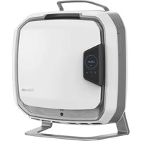
natural_image
Exterior view of a white metal enclosure or duct with mounting holes and internal ventilation slots (no text or symbols visible)Install Guide Guide d'installation Guía para la instalación
PLEASE READ THESE INSTRUCTIONS BEFORE USE. DO NOT DISCARD: KEEP FOR FUTURE REFERENCE.
VEUILLEZ LIRE CES INSTRUCTIONS AVANT D'UTILISER L'APPAREIL. NE PAS JETER : CONSERVER AFIN DE CONSULTER LES DIRECTIVES ULTÉRIEUREMENT, EN CAS DE BESOIN.
• Air Purifier (1X)
• Hybrid Filters w/ Pre-Filter (1X)
• 16ft mounting cables with clutches (4X)
- Centering Blocks (4X)
- User Manual (1X)
TOOLS REQUIRED FOR INSTALLATION
- Gloves
- Ladder/Step Stool
• Straight or 90° Conduit Connector - Wire Nuts
- Level
- Tape
NOTE: Two people are required, three people recommended, for easy and proper installation.
NOTE: We recommend removing additional adjacent ceiling tiles for easiest installation.
NOTE: It is required to remove one cross-tee in the ceiling grid.
- Two adjacent, unobstructed 24" x 24" drop ceiling tiles with at least 18" clearance above the drop ceiling
- Mounting hooks or location installed to local code and capable of holding the weight of the system
- For ease of installation and optimal placement of unit in the grid, it is HIGHLY RECOMMENDED that either hooks be drilled into the ceiling, or strut channels be used to loop cables if there are no existing mounting points available above the perimeter of the housing.
NOTE: Do not install next to a return or register.
NOTE: Shut off circuit breaker to installation area before beginning installation.
INSTALLATION INSTRUCTIONS
natural_image
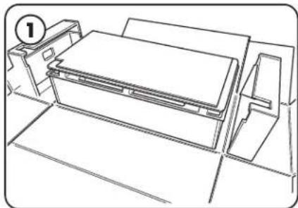
Line drawing of a printer with a paper holder and baseplate, no text or symbols presentBefore beginning installation, ensure that a qualified electrician has run a 120V circuit to the installation area. Remove unit from packaging and stage on a tabletop or other surface under or near installation area with door facing upwards.
natural_image
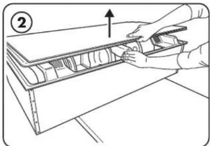
Line drawing of a hand holding a tool interacting with a mechanical component (no text or symbols)Open unit door by depressing the latch button and pulling upward. Have one person hold the door open while filter and hardware are removed.
NOTE: Do not remove corrugate support trays attached to the door yet.
natural_image
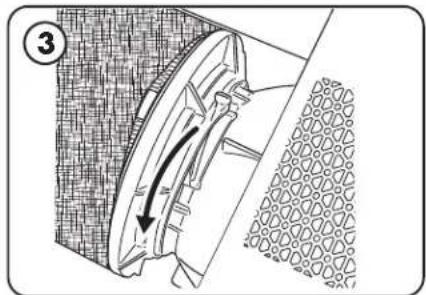
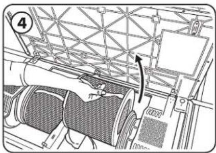
Technical diagram of a mechanical component with directional arrow indicating motion (no text or symbols)Disengage the filter clamp lever until a click is heard.
NOTE: Locking/ unlocking motions are in opposite directions between left and right filter changing mechanisms.
natural_image
Technical line drawing of a mechanical assembly with no visible text or symbolsPull filters out by the straps and set aside for now.
natural_image
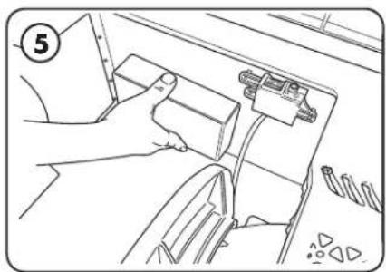
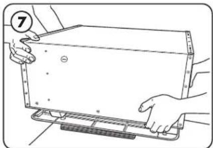
Line drawing of a hand holding a device with cable and connectors, no text or symbols presentRemove mounting hardware and verify included part quantities.
natural_image
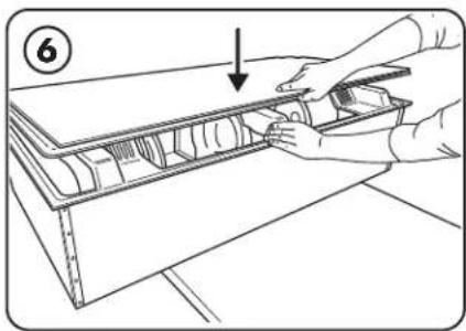
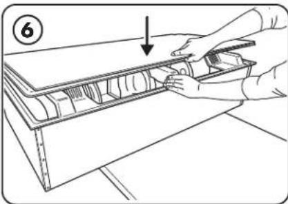
Line drawing of a hand using a tool to cut or install a component on a wooden shelf (no text or symbols)Close the door until a click is heard. Depending on type of ceiling, attach proper mounting hardware above installation area per local regulations for supporting a 92 lb (42kg) fixture. Ideally the mounting locations would be at the four corners of a 23" x 46" rectangle.
natural_image
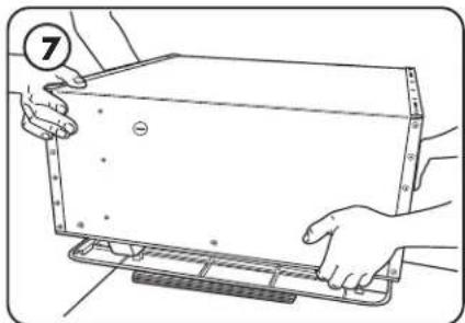
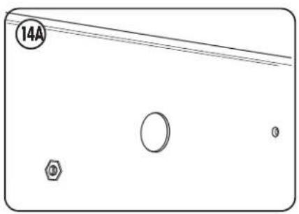
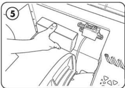
Illustration of hands holding a rectangular object with measurement markings, no text or symbols presentLift and rotate unit before setting door-side down on the provided trays. Determine which electrical knockout will be used and remove it.
natural_image
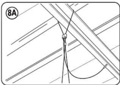
Diagram of a rope tied to a hook, with diagonal lines and a numbered label (8A) in the corner (no text or symbols on the diagram itself)Loop open end of cables through intended support or hardware.
natural_image
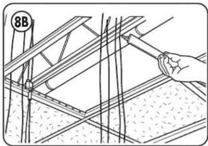
Illustration of a hand using a tool to install or install a structural frame, with no visible text or symbols.Remove cross-tee where unit will be installed.
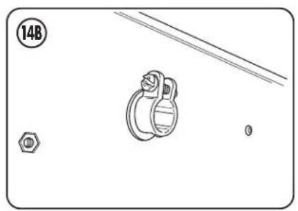
Use provided cable clutch hardware to secure each cable.
WARNING: do not place directly on any flat surface as this will damage the sensor that sticks below the bottom surface.
natural_image
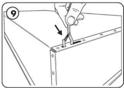
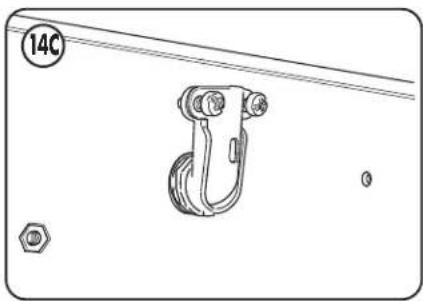
Illustration of a hand using a tool to adjust or install a component, with no visible text or symbolsSecure the hooks from the provided aircraft cabling to the housing through the mounting holes.
natural_image
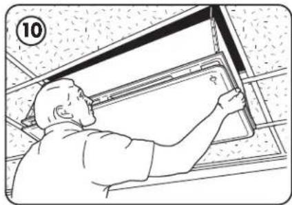
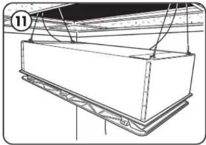
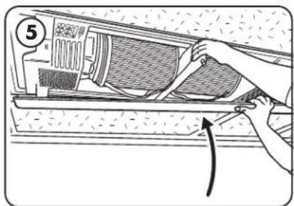
Line drawing of a worker installing or adjusting a ceiling panel (no text or symbols present)Have one or two people slowly lifting the machine while the other pulls the free end of the cables to keep them taut.
natural_image
Technical line drawing of a mechanical assembly with no visible text or symbolsRaise the unit until the top of the housing is just below the grid.
Alternate slowly raising each side to keep the unit relatively level during lifting.
NOTE: If unit is raised too high, have one person raise the unit while the other depresses the spring section on the wire clutch, allowing the cable to be loosened.
WARNING: During lifting ensure hooks stay oriented correctly and do not get misaligned or they may not hold properly.
CAUTION: To reduce the risk of injury to persons, install fan at least 2.1 m (6.9 ft) above the floor.
natural_image
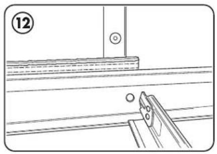
Technical line drawing showing a mechanical assembly with a tool and circular components (no text or symbols)Check below units for visible gaps. If needed, add centering blocks between unit and grid. Trim out as desired.
natural_image
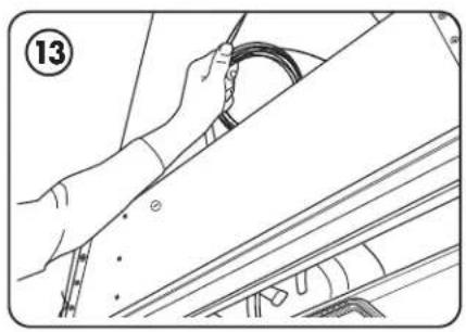
Line drawing of hands installing a cable on a vehicle roof (no text or symbols)Coil and wrap remaining cable out of the way. Do not trim excess cable lengths.
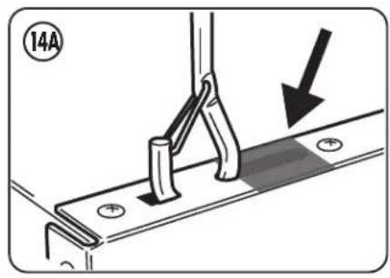
Tape off the hook slots as shown.
Working from above the unit, attach a UL approved straight or 90° elbow to connect conduit.
natural_image
Technical diagram showing a mechanical component with a bolt and nut, no text or symbols present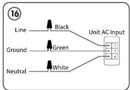
flowchart
graph LR
    A["Line"] --> B["Black"]
    C["Ground"] --> D["Green"]
    E["Neutral"] --> F["White"]
    B --> G["Unit AC Input"]
    D --> G
    F --> G
natural_image
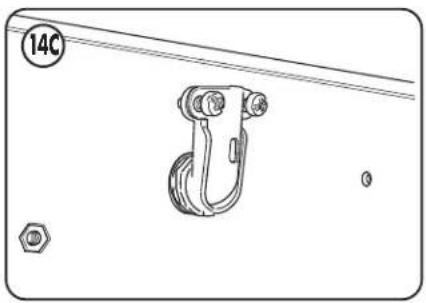
Technical line drawing of a mechanical hook assembly with mounting holes and a numbered circle (14C), no text or symbols present.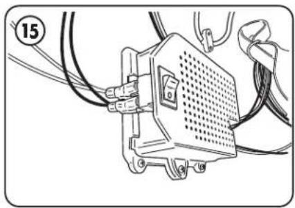
natural_image
Technical line drawing of an electronic device with wires and connectors (no text or symbols)Ensure power switch located on the power supply is in the off position before proceeding with connecting any wires.
Have a qualified electrician connect the ground, line, and neutral to fixture per local electrical codes.
Turn on power supply switch.
Now the unit is set up and can be controlled with the buttons behind the filter door.
All wirings connected in junction box should be connected with twist connectors.
FILTER INSTALLATION PROCEDURE
Unit will notify you when filter needs to be changed with a red led visible on the bottom of the unit.
For replacement filters, please visit: www.fellowes.com
natural_image
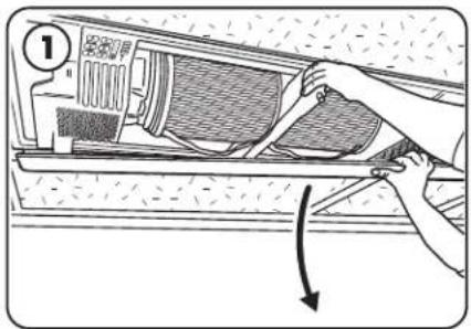
Illustration of a hand adjusting a component inside a washing machine (no text or symbols visible)Open the door by depressing the latch button and pulling down on the door.

natural_image
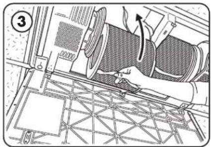
Technical line drawing of a mechanical assembly with circular components and structural supports (no text or symbols)Remove new filter from protective bag and properly dispose of bag.
Holding the filter by the strap, align support cleat with slot.
natural_image
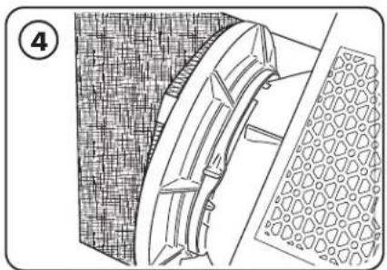
Technical diagram of a mechanical assembly with no visible text or symbolsGently push in filter until a click is heard.
NOTE: if top and bottom supports are not properly aligned, the filter will not sit properly and can damage the unit.
natural_image
Technical line drawing of a mechanical component with textured surfaces and a meshed base (no text or symbols)Secure filter into place by moving filter clamp lever back into the locked position until a click is heard. NOTE: Locking/unlocking motions are in opposite directions between left and right filter changing mechanisms.
natural_image
Illustration of a hand using a tool to adjust or install air conditioner panel (no text or symbols visible)Close door until a click is heard. After closing door, press door closed on corners and directly beneath latch to ensure magnets and latch are fully secured.
CONTENU DE L'EMBALLAGE
natural_image
Line drawing of a printer or printer setup with no visible text, numbers, or symbolsnatural_image
Line drawing of hands installing or adjusting a mechanical component with an arrow indicating upward motion (no text or symbols present)natural_image
Technical diagram of a mechanical component with directional arrows, no visible text or symbolsnatural_image
Technical line drawing of a mechanical assembly with no visible text or symbolsPull filters out by the straps and set aside for now.
natural_image
Line drawing of a hand holding a device with cables and connectors (no text or symbols)Remove mounting hardware and verify included part quantities.
natural_image
Illustration of hands installing or adjusting a mechanical component on a shelf (no text or symbols visible)Close the door until a click is heard. Depending on type of ceiling, attach proper mounting hardware above installation area per local regulations for supporting a 92 lb (42kg) fixture. Ideally the mounting locations would be at the four corners of a 23" x 46" rectangle.
natural_image
Illustration of two hands holding a rectangular electronic device with a numbered circle (7) and no visible text or symbolsnatural_image
Pure electrical circuit lines without any symbolsnatural_image
Technical line drawing of a structural framework with a hand holding a tool, no visible text or symbolsnatural_image
Illustration of a hand using a tool to adjust or install a component, with no visible text or symbolsnatural_image
Line drawing of a person installing or adjusting a ceiling panel (no text or symbols present)natural_image
Technical line drawing of a mechanical assembly with no visible text or symbolsnatural_image
Technical line drawing of a mechanical assembly with no visible text or symbolsnatural_image
Line drawing of a person using a cable to install a component, no text or symbols presentnatural_image
Mechanical assembly diagram showing a bracket with mounting holes and a downward arrow indicating motion (no text or symbols)natural_image
Pure diagram of a rectangular container with four circular features and a labeled circle (14A), no text or symbols present.natural_image
Technical diagram showing a pulley mechanism with a bolt and nut, no text or symbols present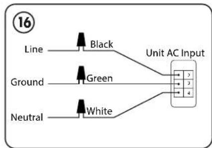
flowchart
graph LR
    A["Line"] --> B["Black"]
    C["Ground"] --> D["Green"]
    E["Neutral"] --> F["White"]
    B --> G["Unit AC Input"]
    D --> G
    F --> G
natural_image
Technical line drawing of a mechanical hook assembly with mounting holes and a numbered circle (14C), no text or symbols present.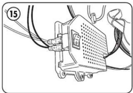
natural_image
Technical line drawing of an electronic device with wires and connectors (no text or symbols)natural_image
Illustration of a hand using a tool to adjust or install air conditioner unit panel (no text or symbols visible)natural_image
Technical line drawing of a mechanical assembly with circular components and structural beams (no text or symbols)natural_image
Technical diagram of a mechanical assembly with no visible text or symbolsnatural_image
Technical line drawing of a mechanical component with textured surfaces and a meshed base (no text or symbols)natural_image
Illustration of a hand installing or adjusting a component on a wall, with no visible text or symbols.natural_image
Line drawing of a printer with paper and cover, no text or symbols presentnatural_image
Line drawing of a hand holding a tool interacting with a wooden shelf panel (no text or symbols)natural_image
Technical diagram of a mechanical component with directional arrow indicating motion (no text or symbols)natural_image
Technical diagram of a mechanical assembly with no visible text or symbolsnatural_image
Line drawing of a hand holding a small object inside a vehicle's dashboard, with no visible text or symbolsnatural_image
Line drawing of hands installing or adjusting a mechanical component inside a storage cabinet (no text or symbols)natural_image
Illustration of hands holding a rectangular object with measurement markings, no text or symbols presentnatural_image
Pure technical line drawing of a rope tied with a hook, no text or symbols presentnatural_image
Illustration of a hand using a tool to install or install a structural frame, no text or symbols presentnatural_image
Illustration of a hand using a tool to adjust or install a component on a metal bracket (no text or symbols)natural_image
Line drawing of a person installing or adjusting a ceiling panel (no text or symbols present)natural_image
Technical line drawing of a rectangular mechanical component with mounting brackets and structural supports (no text or symbols)natural_image
Technical line drawing showing a mechanical assembly with a pin and base plate (no text or symbols)natural_image
Line drawing of a person using a cable to install a car (no text or symbols present)natural_image
Mechanical assembly diagram showing a bracket with mounting holes and a downward arrow indicating motion (no text or symbols)natural_image
Pure diagram of a rectangular object with internal symbols and lines, no readable text or labelsnatural_image
Technical diagram showing a mechanical component with a bolt and nut, no text or symbols present