1095 - Measuring equipment PeakTech - Free user manual and instructions
Find the device manual for free 1095 PeakTech in PDF.


| Product type | Bipolar voltage tester |
| Brand | PeakTech |
| Model | 1095 |
| AC/DC voltage range | 12 V to 690 V |
| Display | LED (12, 24, 36, 50, 120, 230, 400, 690 V) with polarity and AC indicators |
| Continuity test | Yes, threshold < 300 kΩ, audible and visual signal |
| Single-pole phase test | Yes, from 100 V to 690 V AC |
| Phase rotation (three-phase) | Yes, left/right display (L/R) |
| Measuring tip lighting | Yes, dedicated button |
| Self-test | Yes, self-test button |
| Overvoltage category | CAT III 690 V / CAT IV 600 V |
| Protection rating | IP64 (dust and splash-proof) |
| Power supply | 2 AAA 1.5 V batteries (UM-4) |
| Operating temperature | -10 °C to +55 °C |
| Operating humidity | < 85% RH |
| Certifications | TÜV/GS, CE |
| Dimensions (approx.) | 200 x 68 x 40 mm |
| Weight (approx.) | 280 g (including batteries) |
| Maintenance | Clean with a lint-free damp cloth, without penetrating liquid. Do not use harsh detergents. |
| Battery replacement | Open the compartment at the back, replace with 2 AAA 1.5 V batteries observing polarity. |
| Repairability | Repairs by qualified service technician only. Opening prohibited by user. |
Frequently Asked Questions - 1095 PeakTech
User questions about 1095 PeakTech
0 question about this device. Answer the ones you know or ask your own.
Ask a new question about this device
Download the instructions for your Measuring equipment in PDF format for free! Find your manual 1095 - PeakTech and take your electronic device back in hand. On this page are published all the documents necessary for the use of your device. 1095 by PeakTech.
USER MANUAL 1095 PeakTech
Languages on following pages:
English: p. 19
French: p. 36
Italian: p. 54
Spanish: p. 73
natural_image
Close-up of a white and blue electronic device with two batteries inserted, showing charging cable and a logo (no readable text or symbols)This product complies with the requirements of the following directives of the European Union for CE conformity: 2014/30/EU (electromagnetic compatibility), 2014/35/EU (low voltage), 2011/65/EU (RoHS).
Overvoltage category CAT III 690V /
CAT IV 600V; pollution degree 2.
CAT I: For signal level, telecommunication, electronic with small transient over voltage
CAT II: For local level, appliances, main wall outlets, portable equipment
CAT III: Supplied from a cable under earth; fixed installed switches, automatic cut-off or main plugs.
CAT IV: Units and installations, which are supplied over aerial line, which are stand in a risk of persuade of a lightning, i.e. main-switches on current input, over-voltage-diverter, current use counter.
To ensure safe operation of the equipment and eliminate the danger of serious injury due to short-circuits (arcing), the following safety precautions must be observed.
* Do not use this instrument for high-energy industrial installation measurement. This instrument is intended for use in installation over-voltage category III.
* The meter is designed to withstand the stated max voltages. If it is not possible to exclude without doubts that impulses, transients, disturbance or for other reasons, these voltages are exceeded a suitable prescale (10:1) must be used.
* Do not exceed the maximum permissible input ratings (danger of serious injury and/or destruction of the equipment).
* Check test leads and probes for faulty insulation or bare wires before connection to the equipment.
* To avoid electric shock, do not operate this product in wet or damp conditions. Conduct measuring works only in dry clothing and rubber shoes, i. e. on isolating mats.
* Never touch the tips of the test leads or probe.
* Comply with the warning labels and other info on the equipment.
* Always start with the highest measuring range when measuring unknown values.
* Do not subject the equipment to direct sunlight or extreme temperatures, humidity or dampness.
* Do not subject the equipment to shocks or strong vibrations.
* Do not operate the equipment near strong magnetic fields (motors, transformers etc.).
* Keep hot soldering irons or guns away from the equipment.
* Allow the equipment to stabilize at room temperature before taking up measurement (important for exact measurements).
* Do not input values over the maximum range of each measurement to avoid damages of the meter.
* Use caution when working with voltages above 35V DC or 25V AC. These Voltages pose shock hazard.
* With a low battery, the meter might produce false reading that can lead to electric shock and personal injury.
* Fetch out the battery when the meter will not be used for long period.
* Periodically wipe the cabinet with a damp cloth and mid detergent. Do not use abrasives or solvents.
* Do not operate the meter before the cabinet has been closed and screwed safely as terminal can carry voltage.
* Do not store the meter in a place of explosive, inflammable substances.
* Measuring instruments don't belong to children hands.
1.1. Cleaning the cabinet
Clean only with a damp, soft cloth and a commercially available mild household cleanser. Ensure that no water gets inside the equipment to prevent possible shorts and damage to the equipment.
1.2. Explanations of Symbols
 | CAUTION! Refer to the user's manual |
 | Double insolated housing |
| CAT III 690V | Overvoltage category |
 | CE-Certification 2004/22/EC |
 | Right rotation field |
 | Left rotation field |
 | Continuity Tester |
 | Single pole phase tester(100 – 400 VAC 50/60 Hz) and ELV warning |
 | Measurements in voltage carrying circuits |
 | DC- negative polarity |
| DC- positive polarity | |
 | Alternating current (AC) |
| ≈ | Direct and alternating current voltage (DC/AC) |
 | TÜV Rheinland certificated „safety tested“ |
1.3. Introduction
The two pole voltage tester PeakTech ^® 1090 and 1095 with many other measurement functions.
Emphasize here the single-pole phase test (AC), the polarity of the DC test-voltage range, the rotational direction signals for 3-phase systems, the continuity test with visual and audible signal and the measuring point illumination. The PeakTech ^® 1090 also has a test function for residual current circuit breaker (RCD).
These meters are suitable for AC and DC voltage tests in the voltage range of 12 V to 690 V, certified TÜV/GS, and were tested according to EN 61243-3.
Through the dust and splash protection these instruments are suitable for a variety of applications both indoors and outdoors.
1.4 Features
* Voltage measurements from 12 V - 690 V AC / DC
* Direction of rotation display for 3-phase systems
* Measuring point illumination for safe work
* Continuity test with audio-visual signal
* Polarity check for DC voltage measurements
* Single-pole phase test for AC Voltage
* IP64 dust and splash proof
* TÜV / GS safety tested
* Low impedance test function for residual current circuit breaker (RCD).
2. Specifications
2.1. PeakTech ^® 1090
| LCD-Display | 3 1/2-digits (max 1999) with backlight and bargraph |
| Voltage measuring range | 6, 12, 24, 50, 120, 230, 400 AC/DC 690 V DC |
| resolution | 1 V AC/DC |
| accuracy | DCV: +/- 1,0% + 3 dgt. ACV: +/- 1,5% + 3 dgt. |
| ACV frequency range | 50 / 60 Hz |
| voltage detection | automatic |
| polarity detection | full range |
| range detection | automatic |
| response time | 2 ~ 3 per second |
| internal impedance | <1 MΩ |
| Single-Pole Phase Test | |
| voltage range | 100 ... 400 V AC |
| ACV frequency range | 50/60 Hz |
| continuity test | |
| resistance range | <200 kΩ |
| test current | <1 μA |
| overvoltage protection | 400 V AC / 690 V DC |
| rotary field indication | |
| Voltage range (LED's) | 100 ... 400 V |
| ACV frequency range | 50/60 Hz |
| Low impedance test | |
| voltage range | 12 ... 230 V AC/DC |
| low impedance | <6 kΩ |
| general | |
| power supply | 2 x 1,5 V AAA (UM-4) batteries |
| operation temperature | 0 ... 50°C <80% RH |
| overvoltage category | CAT III 690V / CAT IV 600V |
2.2. PeakTech ^® 1095
| LED voltage range | +/-12, 24, 36, 50, 120, 230, 400, 690 VDC |
| 12, 24, 36, 50, 120, 230, 400, 690 VAC | |
| Tolerances | -30% to 0% of reading |
| Voltage detection | automatic |
| Polarity detection | full range |
| Range detection | automatic |
| Response time | < 0.1s LED |
| ACV Frequency range | 50/60Hz |
| Automatic load (RCD) | yes |
| Internal basic load | approx. 2.1 W at 600V |
| Peak current | 1s <0.2A / Is (5s) < 3.5mA |
| Operation time | ED =30s |
| Recovery time | 10 min |
| LED on | about 8V AC/DC |
| Single-pole Phase Test | |
| Voltage range | 100...690 V AC |
| ACV Frequency range | 50/60 Hz |
| Continuity Test | |
| Resistance range | <300 kΩ |
| Test current | 5 μA |
| Overvoltage protection | 690 V AC/DC |
| Rotary Field Indication | |
| Voltage range (LEDs) | 100...400 V |
| Frequency range | 50/60 Hz |
| Measurement principle | double-pole and contact electrode |
| Self-check Test | autotest |
| Power supply | 2x1.5 V “AAA” batteries |
| Power consumption | max.30 mA / approx. 250 mW |
| Temperature range | -10°C up to +55°C |
| Humidity | < 85% relative humidity |
| Overvoltage class | CAT III 690V / CAT IV 600V |
3. Description of the Tester
3.1. PeakTech ^® 1090
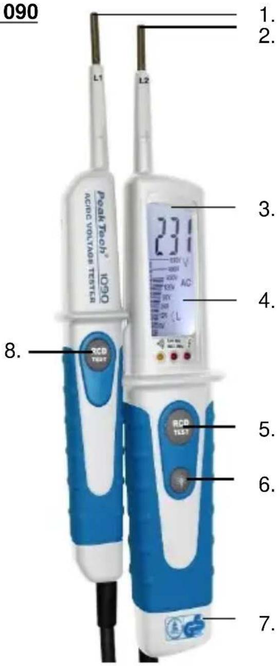
text_image
090 Peak Tech® 1020 AC/DC VOLTAGE TESTER L1 L2 1. 2. 3. 4. 5. 6. 7. 8. RCD TEST 231 V AC L RCD TEST- Test probe – (L1)
- Test probe + (L2)
- Measurement point illumination
- LCD-display
- Button for low impedance test (L2)
- Button for measurement point illumination
- Battery case
- Button for low impedance-test (L1)
3.2. Indicator PeakTech® 1090
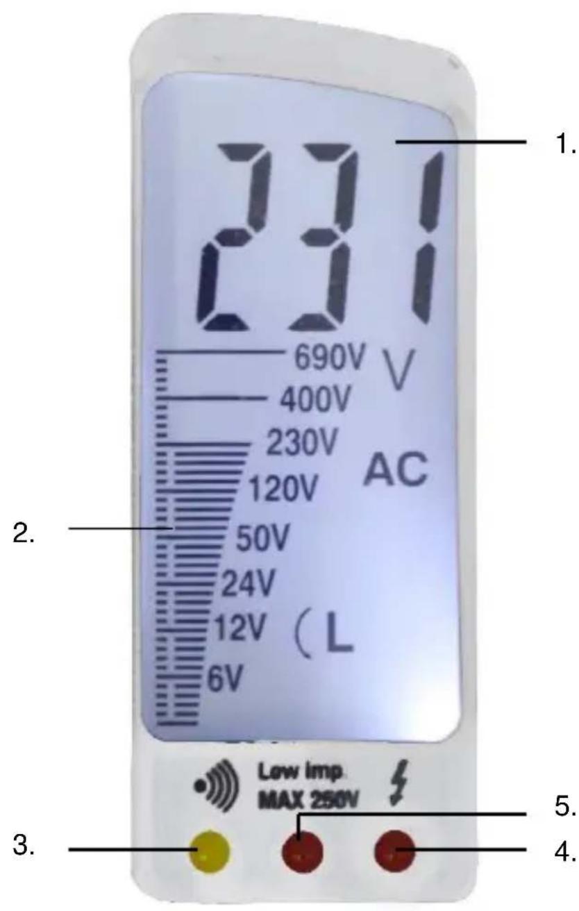
text_image
231 690V V 400V 230V 120V 50V 24V 12V (L 6V) Low imp. MAX 250V 1. 2. 3. 4. 5.- 3 12 -digit LCD-display
- Bargraph
- LED for continuity test
- LED for displaying the 1-pole phase test and ELV warning lamp for 2-pole measurement
- LED for low impedance test
3.3. PeakTech ^® 1095
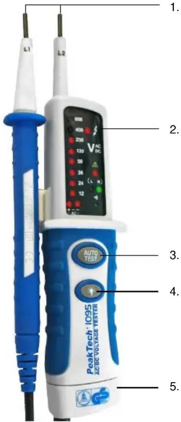
text_image
1. L1 L2 600 400 230 120 50 36 24 12 2. 2. 3. 4. 5. PeakTech 1095 ACTIVE VOLTAGE TESTER AUTO TEST- Probes L1 and L2
- LED display
- Auto-test button
- Key for Measuring point illumination
- Battery compartment with screw on the underside
3.4. Indicator PeakTech® 1095
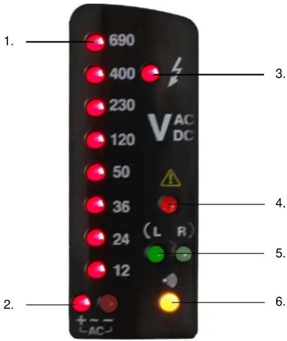
text_image
1. 690 400 230 120 50 36 24 12 V AC DC ( L R ) 4. 5. 6. 2. +~ -AC-- Voltage display 12 - 690 V
- Polarity indication (DC) / Alternating current Display (AC)
- Voltage display / single-pole phase indicator (AC)
- Warning light for voltages above 50 V
- 3 phase rotation indicator system Left / Right
- Indicator for continuity testing
4. Preparation for measuring operating
Function test / self test
* Test the voltage tester on a known source.
* The ELV Warning LED (4) will light on when there is a dangerous voltage present even if the battery is low or if the battery has been removed.
* P 1090: If battery voltage is present, an acoustic warning signal sounds for voltages over 50V AC and 120V DC
PeakTech® 1090
* Hold together the two probes L1 + L2 and short them. The display will illuminate, the audible signal sounds and the LED for the continuity test lights on. The LEDs for the low impedance test and the single-pole phase test are off.
PeakTech ^® 1095
* Caution: To avoid electric shock, disconnect the probes from the power source before you run the auto-test function.
* When press “Auto-Test”- button, all voltage LEDs must be on, also the continuity test’s LED and the buzzer sound. This shows the self-test was done.
4.1. Operation
Voltage Test
* Connect both test probes with power source.
* As from a voltage of >6 V (P 1090) resp. >12 V (P 1095) the voltage tester switches on automatically.
* The voltage is displayed via LCD-display (P 1090) resp. LEDs (P 1095).
* For AC voltages the “AC”-symbol is displayed in the LCD-display (P 1090) resp. the AC-LED is illuminated (P 1095).
* For DC voltages the “DC”-symbol is displayed in the LCD-display (P 1090) resp. the “-DC or +DC” LED is illuminated (P 1095).
* The voltage measurement value is displayed numerically on the LCD display (P 1090) or over seven LEDs (12 \~ 690 V) (P 1095) and shows the applied voltage.
* The polarity of the voltage displayed refers to the instrument test probe (L2).
Single-pole phase Test
* The single-pole phase test is only possible when batteries are installed and in good condition.
* The single-pole phase test starts at an AC voltage of approx. 100 V (pole >100 V AC).
* When using single-pole phase tests to determine external conductors the display function may be impaired under certain conditions (e. g. for insulating body protective equipment on insulation locations).
* The single-pole phase testing is not appropriate to determine whether a line is live or not. For this purpose, the double-pole voltage test is always required.
* The LED is illuminated in the display.
* Probe "L2" with voltage source connected to the single-pole phase test LED lights. Using the P 1090 simultaneously the LCD display lights, but it does not display any voltage value. So, please perform the two-pole voltage test afterwards.
Continuity Test
* The continuity test is only possible if there are batteries with sufficient power.
* Continuity test works only on non-active conductors.
* Use both probes to measure the conductor.
* Continuity test will only work with circuit resistances <200 kΩ (P 1090) / <300 kΩ (P 1095).
* A continuous beep sounds and the corresponding LED lights.
Rotary Field Indication
* The voltage testers are equipped with a double-pole rotary field indicator. Detection of the rotating field works only with earthed systems. Both handles have to be held tightly in order to ensure a capacitive coupling to the ground.
* The rotary phase indication is always active. The symbols “R” or “L” are always displayed. However, the rotary direction can only be determined within a 3 - phase system. The instrument indicates the voltage between two external conductors.
* Connect the instrument test probe “L2” with the supposed phase “L2” and the handle test probe “L1” with the supposed phase “L1”.
* The voltage and the rotary field direction are displayed on LCD (P 1090) resp. LED (P 1095).
* “R” signifies that the supposed phase L1 is the actual phase L1 and the supposed phase L2 is the actual phase L2.
* “L” signifies that the supposed phase L1 is the actual phase L2 and the supposed phase L2 is the actual phase L1.
* When re-testing with exchanged test probes the opposite symbol has to be illuminated.
Measurement Point Illumination
* Voltage testers are equipped with a measurement point illumination feature.
* Thus, working under bad lighting conditions (e.g. division switch cabinets) is made easier.
* Press button for measurement point illumination 🙏 on instrument.
* A bright LED lights now the area before the probe "L2".
Voltage measurement with low internal impedance (P 1090)
This function is particularly useful for testing installations. Due to the lowered internal impedance.
Capacitive voltage is suppressed. The reading shows the actual voltage applied. Similarly, measuring phase “L1” on earth wire “PE” may trigger fault-current circuit breakers (FI or RCI). This measuring procedure can be used for measurements above 12V. Always hold the voltage tester by the handles designed for this purpose. Never touch the device beyond the handle ends.
Hold the two test tips onto the measuring points to be tested. Press the two push-buttons and simultaneously. The applied voltage is shown on the LCD display. The Low-Imp LED signals low impedance measurement.
To test a residual current circuit breaker, connect test probe "L2" to the phase of a grounded wall outlet and test probe "L1" to the earth terminal of the grounded outlet. If you now press both "RCD Test" buttons at the same time, a small test current is triggered, which should trigger the residual current circuit breaker. Before testing, ensure that no critical equipment (computer servers, etc.) is connected to this circuit as a successful test will turn it off.
Caution!
The maximum permitted duty cycle in low impedance operating mode is 5 seconds for voltage up to 250 V and 3 seconds for voltages up to 690V. When this time has lapsed, wait for 10 minutes.
5. Replacing the batteries
* Short the Test-probes to test and if no signal is heard or the AUTO-test no longer works, the batteries should be replaced
* Disconnect the voltage detector completely from any power source
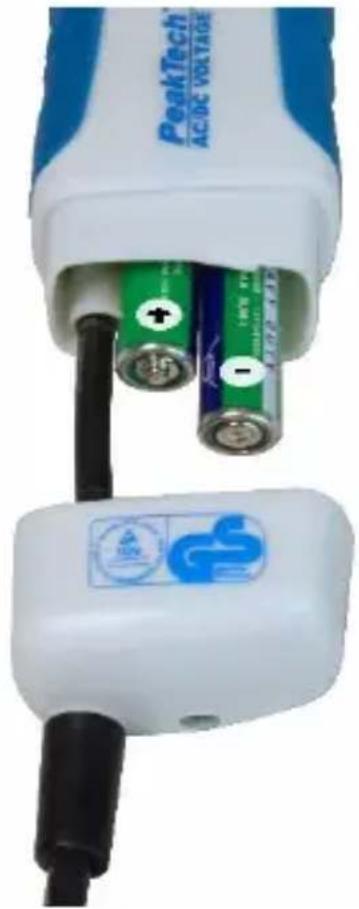
* Open the battery compartment with the cross-bolt on the bottom of the unit
* Remove the battery cover off down
* Replace the batteries with new ones of the same type 1,5V "AAA" (UM4 R03)
* Ensure the correct battery polarity
* Close the battery compartment and re-screw the cover completely
natural_image
Close-up of a white electronic device with two batteries and a black cable inserted, showing no visible text or symbols.Notification about the Battery Regulation
The delivery of many devices includes batteries, which for example serve to operate the remote control. There also could be batteries or accumulators built into the device itself. In connection with the sale of these batteries or accumulators, we are obliged under the Battery Regulations to notify our customers of the following:
Please dispose of old batteries at a council collection point or return them to a local shop at no cost. The disposal in domestic refuse is strictly forbidden according to the Battery Regulations. You can return used batteries obtained from us at no charge at the address on the last side in this manual or by posting with sufficient stamps.
Contaminated batteries shall be marked with a symbol consisting of a crossed-out refuse bin and the chemical symbol (Cd, Hg or Pb) of the heavy metal which is responsible for the classification as pollutant:

chemical
Chemical symbol for Cd⁴⁻ (manganthol) with crossed and unmarked crossings indicating electron density or fragmentation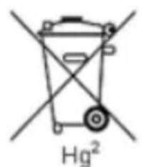
chemical
Chemical symbol for a magnesium (Hg²) ion with crossed electrons and a central atom
chemical
Chemical symbol for Pb³ (potassium boric acid) with crossed and unshaded components- "Cd" means cadmium.
- "Hg" means mercury.
- "Pb" stands for lead.
All rights, also for translation, reprinting and copy of this manual or parts are reserved. Reproductions of all kinds (photocopy, microfilm or other) only by written permission of the publisher.
This manual is according the latest technical knowing. Technical alterations reserved.
We herewith confirm that the units are calibrated by the factory according to the specifications as per the technical specifications.
We recommend to calibrate the unit again, after 1 year.
©PeakTech®
natural_image
Close-up of a white and blue electric shock absorber with two batteries inserted, showing charging cable and battery terminal (no text or symbols visible)natural_image
Close-up of a white and blue electronic device with two batteries inserted, showing charging cable and a logo (no readable text or symbols)natural_image
Close-up of a white electric shock absorber with two batteries and a blue charging plug (no visible text or symbols)DE-22926 Ahrensburg / Germany
+49 (0) 4102 97398-80 +49 (0) 4102 97398-99
info@peaktech.de www.peaktech.de