3710 - Measuring equipment PeakTech - Free user manual and instructions
Find the device manual for free 3710 PeakTech in PDF.

User questions about 3710 PeakTech
0 question about this device. Answer the ones you know or ask your own.
Ask a new question about this device
Download the instructions for your Measuring equipment in PDF format for free! Find your manual 3710 - PeakTech and take your electronic device back in hand. On this page are published all the documents necessary for the use of your device. 3710 by PeakTech.
USER MANUAL 3710 PeakTech
text_image
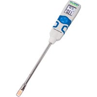
Image displaying multiple electronic testing devices with visible labels and digital displays, including a 33.500 μF display.PeakTech® 3710
Bedienungsanleitung
text_image
Image displaying multiple electronic test equipment with waveform graphs and digital displays, including a 33.00K digital display.PeakTech® 3710
Operation manual
Pen Meter for SMD
1. SAFETY PRECAUTIONS
This product complies with the requirements of the following European Community Directives: 2004/108/EC (Electromagnetic Compatibility) and 2006/95/EC (Low Voltage) as amended by 2004/22/EC (CE-Marking). Pollution degree 2.
To ensure safe operation of the equipment and eliminate the danger of serious injury due to short-circuits (arcing), the following safety precautions must be observed.
Damages resulting from failure to observe these safety precautions are exempt from any legal claims whatever.
* Caution : Avoid working with voltages above 50VDC or 36VAC rms. Such voltages pose a shock hazard and damage the meter
* Do not use this instrument for high-energy industrial installation measurement.
* Do not place the equipment on damp or wet surfaces.
* Disconnect test leads or probe from the measuring circuit before switching modes or functions.
* To avoid electric shock, disconnect power to the unit under test and discharge all capacitors before taking any resistance measurements.
* Check test leads and probes for faulty insulation or bare wires before connection to the equipment.
* To avoid electric shock, do not operate this product in wet or damp conditions. Conduct measuring works only in dry clothing and rubber shoes, i. e. on isolating mats.
* Never touch the tips of the test leads or probe.
* Comply with the warning labels and other info on the equipment.
* The measurement instrument is not to be to operated unattended.
* Always start with the highest measuring range when measuring unknown values.
* Do not subject the equipment to direct sunlight or extreme temperatures, humidity or dampness.
* Do not subject the equipment to shocks or strong vibrations.
* Do not operate the equipment near strong magnetic fields (motors, transformers etc.).
* Keep hot soldering irons or guns away from the equipment.
* Allow the equipment to stabilize at room temperature before taking up measurement (important for exact measurements).
* Replace the battery as soon as the battery indicator "BAT" appears. With a low battery, the meter might produce false reading that can lead to electric shock and personal injury.
* Fetch out the battery when the meter will not be used for long period.
* The meter is suitable for indoor use only
* Do not operate the meter before the cabinet has been closed and screwed safely as terminal can carry voltage.
* Do not store the meter in a place of explosive, inflammable substances.
* Do not modify the equipment in any way
* Do not place the equipment face-down on any table or work bench to prevent damaging the controls at the front.
* Opening the equipment and service – and repair work must only be performed by qualified service personnel
* Measuring instruments don't belong to children hands.
Cleaning the cabinet
Clean only with a damp, soft cloth and a commercially available mild household cleanser. Ensure that no water gets inside the equipment to prevent possible shorts and damage to the equipment.
1.1. Symbols used in this manual and on the meter:

Caution: refer to the instruction manual. Incorrect use may result in damage to the device or its components.

conforms to CE-directives

Double insulation (Protection class II)
1.2 General Instructions
This auto scan pen-type SMD-multimeter could fast precise measure small chip components. To get the best service from this meter, please read this user's manual carefully and observe the detailed safety precautions strictly.
2. TECHNICAL SPECIFICATIONS
2.1 General specifications
Display
3 5/6 digit, 12 mm LCD display with function annunciators, max. indication 5999
Max. Voltage between
terminals and earth ground
50V DC / 36V Acrms
Ranging method
Auto or manual
Sampling rate
3 times / second
Polarity indication
“-” displayed automatically
Overload indication
"OL" displayed
Low battery indication
"BAT-Symbol" displayed
Auto Power Off
after 10 minutes
Power supply
2x 1,5V bottom cells (AG-13)
Operating temperature:
0\~40 ^ C, (<80% RH);
< 2000 m
Storage temperature:
-10\~60°C, (<70% RH, battery
removed)
Dimensions:
183(L) × 35(W) × 20(H) mm
Weight:
65g. . Approx. (battery included)
2.2 Measurement specifications
* Accuracy: ±(% of reading + number of digits) at 18°C to 28°C (64°F to 82°F) with relative humidity to 80%.

Caution when working with
voltages above 50V DC or
36V AC rms.
2.3 Resistance
| Range Resolution | Accuracy | |
| 600 Ω 0 | 1 Ω | ±(1.2% of rdg +2digits) |
| 6 kΩ | 1 Ω | |
| 60 kΩ | 10 Ω | |
| 600 kΩ | 100 Ω | |
| 6 MΩ | 1 kΩ | |
| 60 MΩ | 10 kΩ ±(2% of rdg +5digits) | |
2.4 Capacitance
| Range | Resolution | Accuracy |
| 6nF | 1pF | ±(5.0% of rdg +5 digits) |
| 60nF | 10pF | ±(3.0% of rdg +3 digits) |
| 600nF | 100pF | |
| 6μF | 1nF | |
| 60μF | 10nF | ±(5.0% of rdg +3 digits) |
| 600μF | 100nF | |
| 6mF | 1uF | |
| 60mF | 10uF |
Keep two pins of the capacitance in short before measuring
2.5 Diode Test
| Range description Test | Condition | |
| 2V | Display read approx. forward voltage of diode | Forward DC Current: approx. 1mA Reversed DC Voltage: approx. 2.8V |
2.6 Continuity check
The buzzer generates 2kHz beep whenever the reading is less than 30Ω.
3. DESCRIPTION
3.1 Instrument Familiarization
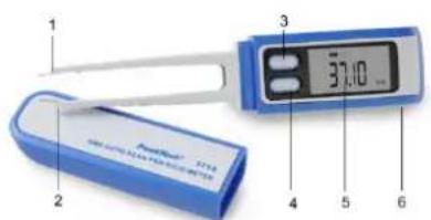
text_image
1 2 3 37.10 4 5 6- cathode
- anode
- "RANGE" key
- "FUNC." key
- LCD display
- Battery cover
3.2 LCD Display
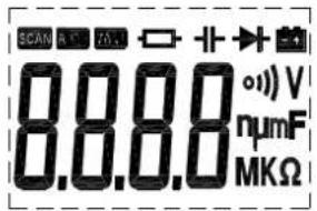
text_image
SCAN R1 TA 8.8.8 (V) numF MKΩ3.3 FUNC. key----Function key
Press this key longer than 1 second, the meter will turn on and enter auto scan mode.
Press this key less than 1 second could select the target measurement function.
Press this key longer than 2 seconds, the meter will enter sleep mode.
3.4 RANGE key ----Changes range
When automatic mode pressing this key less than 1 second, the meter will enter manual mode.
When manual mode pressing this key longer than 1 second, the meter will enter automatic mode.
While in manual mode, pressing this key less than 1 second to change the full-scale range.
3.5 Measurement specifications
* Accuracy: ± (% of reading + number of digits) at 18°C to 28°C (64°F to 82°F) with relative humidity to 80%.

Caution when working with voltages above 50V DC or 36V AC rms.
4.1 Auto scan measurement mode
Pressing this key longer than 1 second, the meter will turn on and enter auto scan mode.now.you can measurement: ohm, diode, capatitance and continuity check.
NOTE:
The range when auto scan mod:
Ohm: 600.0Ω\~6.000MΩ;
Cap: 6nF\~600μF.
4.2 Resistance measurement

To avoid electrical shock or damages to the meter under test, disconnect circuit power and discharge all high-voltage capacitors before measuring resistance.
Press FUNC. Key and select the function at
- - mode. Connect the test clip to the object being measured and the measured value will show on the display.
NOTE:
When this mode the RANGE key is available, when the input is not connected, i.e. at open circuit, the figure "OL" will be displayed for the overrange condition.
4.3 Capacitance measurement

To avoid electrical shock or damages to the meter under test, disconnect circuit power and discharge all high-voltage capacitors before measuring capacitance. Keep two pins of the capacitance in short before measuring.
Press FUNC. Key and select the function at mode.
Connect the test clip to the capacitor being measured and read the displayed value.
NOTE:
When this mode the RANGE key is available. discharge the capacitor before measuring.
4.4 Diode measurement

To avoid electrical shock or damages to the meter under test, disconnect circuit power and discharge all high-voltage capacitors before testing diodes.
Press FUNC. Key and select the function at mode.
Connect the + pin to the anode, the - pin to the cathode of the diode under testing.
The meter will show the approx. forward voltage of the diode. If the lead connection is reversed, only figure "OL" displayed.
4.5 Continuity check
Press FUNC. Key and select the function at mode connect the test clip to the resistance. If continuity exists (i.e., resistance less than 30Ω) built – in buzzer will sound.
5. AUTO POWER OFF (APO)
To extend the battery life, Auto Power Off function is provided. If no key operations of range changing happen about 10 minutes, the meter will be turned off automatically.
When APO happens, the state of the meter is saved.
6. MAINTENANCE
6.1 General Maintenance
Periodically wipe the case with a damp cloth and mild detergent. Do not use abrasives or solvents.
6.2 Battery replacement

Before replacing the battery, disconnect test probes from any circuit under test, turn the meter off and remove test probes from the input terminals.
Use the following procedure:
When the battery voltage drop below proper operation range the 📄 symbol will appear on the LCD display and the battery need to be replaced.
Press the battery cover and towards arrowhead direction to open the battery cover. Replace the battery with two new 1.5V batteries (AG13). Replace the battery cover.
Statutory Notification about the Battery Regulations
The delivery of many devices includes batteries, which for example serve to operate the remote control. There also could be batteries or accumulators built into the device itself. In connection with the sale of these batteries or accumulators, we are obliged under the Battery Regulations to notify our customers of the following:
Please dispose of old batteries at a council collection point or return them to a local shop at no cost. The disposal in domestic refuse is strictly forbidden according to the Battery Regulations. You can return used batteries obtained from us at no charge at the address on the last side in this manual or by posting with sufficient stamps.

Batteries, which contain harmful substances, are marked with the symbol of a crossed-out waste bin, similar to the illustration shown left. Under the waste bin symbol is the chemical symbol for the harmful substance, e.g. "Cd" for cadmium, "Pb" stands for lead and "Hg" for mercury.
You can also find this notification in the paperwork accompanying the goods delivery or in the manufacturer's operating instructions.
You can obtain further information about the Battery Regulations from the Bundesministerium für Umwelt, Naturschutz und Reaktorsicherheit (Federal Ministry of Environment, Nature Conservation and Reactor Safety).
All rights, also for translation, reprinting and copy of this manual or parts are reserved. Reproduction of all kinds (photocopy, microfilm or other) only by written permission of the publisher.
This manual considers the latest technical knowing. Technical changings which are in the interest of progress reserved. e herewith confirm, that the units are calibrated by the factory according to the specifications as per the technical specifications. We recommend to calibrate the unit again, after 1 year.
PeakTech ^® 10/2015/th
PeakTech®
text_image
Image displaying multiple electronic testing devices with visible labels and digital displays, including a 33.500 μF display.PeakTech® 3710
Mode d'emploi