
GASTRO M 1808 CSG A DL DR C2 U - Fridge GRAM - Free user manual and instructions
Find the device manual for free GASTRO M 1808 CSG A DL DR C2 U GRAM in PDF.

| Product type | Professional refrigerator-freezer table |
| Brand | Gram |
| Model | GASTRO M 1808 CSG A DL DR C2 U |
| Dimensions (W x D x H) | Approximately 1800 x 700 x 850 mm |
| Weight | Approximately 120 kg |
| Power supply | 220-230 V ~ 50 Hz |
| Temperature range | Adjustable from -35 °C to +25 °C |
| Automatic defrost | 4 cycles per 24 hours, manual defrost possible |
| Digital display | Yes, with error codes F1, F2, F3 |
| Keyboard lock | Yes, by code 123P |
| Temperature alarm | Yes, with adjustable thresholds and relay for remote alarm |
| Reversible door | Yes, reversal possible from right to left |
| Ventilation | Ensure air circulation; do not obstruct grilles |
| Cleaning | Mild soapy solution; do not use chlorine; clean the condenser |
| Exterior material | Stainless steel |
| Adjustable feet | Yes, for leveling |
| Defrost water drainage | Via hose to an evaporation tray |
| Installation environment | Avoid direct exposure to sunlight, heat sources, and high concentrations of chlorine/acid |
| Condenser maintenance | Brush or vacuum cleaner; removable filters dishwasher-safe at 50 °C max |
| Repairability index | Not specified |
Frequently Asked Questions - GASTRO M 1808 CSG A DL DR C2 U GRAM
User questions about GASTRO M 1808 CSG A DL DR C2 U GRAM
0 question about this device. Answer the ones you know or ask your own.
Ask a new question about this device
Download the instructions for your Fridge in PDF format for free! Find your manual GASTRO M 1808 CSG A DL DR C2 U - GRAM and take your electronic device back in hand. On this page are published all the documents necessary for the use of your device. GASTRO M 1808 CSG A DL DR C2 U by GRAM.
USER MANUAL GASTRO M 1808 CSG A DL DR C2 U GRAM
natural_image
Exterior view of a modern stainless steel kitchen appliance with double drawers and control panel (no visible text or symbols)Illustration 1A, 1B, 1C
59
GB | Contents
Location 14
Important! 14
Electrical connection 15
Starting up 16
Temperature setting 17
Error codes on the display 17
Temperature alarm 18
Potential free alarm relay 18
Keylock 18
Defrosting 19
Defrost water 19
Power failure 20
Cleaning 20
Changing door hinge side 21
Service 22
Disposal 22
Illustration 1A, 1B, 1C 59
D
Inhalt
Aufstellen 23
Wichtig ! 23
Stromanschluß 24
Inbetriebnahme 25
Temperaturregelung 26
Illustrations 1A, 1B, 1C 59
NL
Inhoud
natural_image
Technical line drawing of a door with internal compartments and a directional arrow indicating motion (no text or symbols)Bortskaffelse
Congratulations on your new refrigerator/freezer counter.
To ensure that you get optimum use of your new refrigerator/ freezer counter, please read these instructions carefully before putting it to use.
Location
The counter should be located in a dry and adequately ventilated room.
To ensure efficient operation, it must not be placed in direct sunlight or against heat-emitting surfaces.
If the counter is fitted with legs, the legs must be adjusted to ensure that it stands level and not distorted in any way.
If the counter is fitted with castors, it must stand on a flat floor. In time, an uneven floor might distort the counter to the extent that door and drawer operation becomes difficult.
If the counter is to be placed on a plinth, make sure that it stands level and undistorted.
Avoid placement of the counter in a chlorine/acid-containing environment (swimming-bath etc.) due to risk of corrosion.
Important!

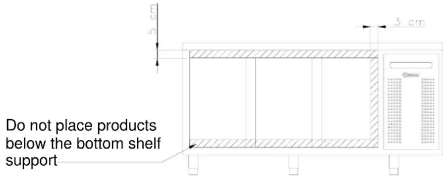
Do not block vent holes in the front panel.
Do not damage the refrigeration system.
Do not use electrical devices inside the cabinet.
To ensure correct and efficient air flow in the counter, the shaded areas must be kept free of products.
All products to be stored, that are not wrapped or packed, must be covered in order to avoid unnecessary corrosion of the inner parts of the counter.

In places where warning triangles and/or screws are used to secure covers around electrical parts, heating elements, compressor, fans, etc., there is a risk of severe injury if covers are removed. Therefore, covers must only be removed by a service technician.
Electrical connection
The counter is intended for connection to alternating current. The connection values for voltage (V) and frequency (Hz) are given on the nameplate.
Power must be connected via a wall socket. The wall socket should be easily accessible. All earthing requirements stipulated by the local electricity authorities must be observed. The counter plug and wall socket should then give correct earthing. If in doubt, contact your local supplier or authorized electrician.

Warning!
This counter must be earthed.
The flexible cord fitted to this appliance has three cores for use with a 3-pin 13-Amp or 3-pin 15-Amp plug. If a B.S. 1363 (13-Amp) fused plug is used, it should be fitted with a 13-Amp fuse.
Important
The wires in this mains lead are coloured in accordance with the following code:
GREEN-AND-YELLOW: EARTH BLUE: NEUTRAL
BROWN: LIVE
The colours of the wires in the mains lead of this appliance might not correspond with the colour marking identifying the terminals in your plug.
Proceed as follows:
Connect the GREEN-AND-YELLOW wire to the plug terminal marked by "E" or an earth symbol, or coloured GREEN-AND-YELLOW.
Connect the BLUE wire to the plug terminal marked "N" or coloured BLACK. Connect the BROWN wire to the plug terminal marked "L" or coloured RED.
Starting up
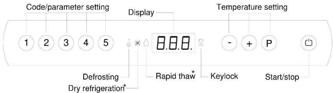
* = no function at this product.
Plug in the counter.

To start, press the START/STOP key.
The figures shown in the display give the actual cabinet temperature and indicate that power is connected.
If the counter does not start immediately, and lights, it is because defrosting is taking place. To cancel the defrost program, press keys P and for more than 3 seconds.
is turned off.
To turn off the cabinet, push for more than 3 seconds.

Servicing:
Make sure the appliance is switched off at the socket before service is performed on electrical parts. It is not sufficient to switch off the cabinet by the START/STOP key as there will still be voltage to some electrical parts of the counter.
Temperature setting
Temperature control:
P Press to see the temperature setting; the display will show the set temperature.
Temperature regulation:
Temperature up: Keep P pressed. At the same time, press +.
Each is pressed the temperature will change one degree. When the display shows the desired temperature let go of the two keys and the setting has been made.
Temperature down: Keep Ⓟ pressed. At the same time, press Ⓕ.
Each is pressed that temperature will change one degree. When the display shows the desired temperature let go of the two keys and the setting has been made.
Error codes on the display
F1 If code F1 is displayed it means that the cabinet temperature sensor is defective and service assistance should be requested. In the meantime the counter itself will maintain the set temperature by the memory of the controller.
F2 If the display alternates between temperature and error code F2 there are problems with the temperature sensor on the evaporator. This has no effect on the operation of the couter, but the sensor should be replaced as soon as possible. Request service assistance.
F3 If the display alternates between temperature and error code F3 there are problems with the temperature sensor on the condenser. This has no effect on the operation of the counter, but the sensor should be replaced as soon as possible. Request service assistance.
NOTE! Applies only to cabinets with built-in compressor.
If the dots in the display flash, it indicates that the condenser temperature is too high. Switch off the counter at the mains and see whether the condenser has been covered. If this is not the case, the high temperature might be the result of dirt on the condenser. The condenser can be cleaned with a brush or vacuum cleaner. Switch on the counter again. After an hour, the counter should run normally. If the dots begins flashing again, request service assistance.
NOTE! Applies only to cabinets with built-in compressor.
Temperature alarm
Temperature alarm – display.
The controller is equipped with a temperature alarm, that monitors the cabinet temperature. The temperature value that activates the alarm, can be set by the user. If the temperature exceeds the set value, the display starts flashing according to the set time delay.
To reset the alarm, turn the cabinet on and off.
Setting the alarm value (setting range -35°C to +25°C – default +25°C):
- Push P + 1 for more than 3 seconds.
- Push + until the display shows dPL.
- Push Ⓟ to view the alarm value.
- Use the + or - keys to set the value.
- Push the Ⓟ key to confirm the new value. Press ⏻ twice to exit the menu.
Setting the time delay (setting range 0 to 120 min. – default 60 min.):
Proceed as above, except the parameter for time delay is dPt.
Potential free alarm relay
Connector no. 19 on the power PCB is for connecting a remote alarm. A relay closes the circuit, if the temperature has been too high or too low according to the set time delay.
Setting the upper alarm value (setting range -35°C to +25°C):
- Push P + 1 for more than 3 seconds.
- Push + until the display shows HAr.
- Push ^P to view the alarm value.
- Use the + or - keys to set the value.
- Push the Ⓟ key to confirm the new value. Press ⏻ twice to exit the menu.
Setting the lower alarm value (setting range -35^ to +25^ ):
Proceed as above, except the parameter for lower alarm value is LAr.
Setting the time delay (setting range 0 to 120 min. – default 60 min.):
Proceed as above, except the parameters for upper and lower alarm time delay are HAt and LAt respectively.
Keylock
The keypad can be locked by keying the code: 123P (default setting). 📋 lights to indicate that the keys are locked, and a short beep sounds. Now it is not possible to use the keys for temperature setting etc.
The same code is to be used for unlocking the keypad again.
To change the code, see the Operation- and servicemanual.
Defrosting
Defrosting is automatically performed 4 times every 24 hours. If the cabinet is operating under severe load (frequent door opening and frequent replenishment) manual defrosting can become necessary. The cabinet can be manually defrosted by switching it off and on. It will then start to defrost. The next defrost will occur 6 hours later. ● lights up to indicate a defrosting cycle.

Do not use sharp or pointed objects to accelerate the defrosting process.
The number of daily defrosts can be changed as follows:
- Press + 1 for more than 3 seconds.
- Press + until dEF is shown on the display.
- Press Ⓟ to display the current setting.
- Press ① or - to change the setting.
- Once the required value has been selected, press Ⓟ to confirm the new setting.
- Press twice to exit the menu.
Defrost water
Counters with compressor
Defrost water is led through a pipe, from the evaporator and into a tray behind the condenser.
Here, the water is evaporated by heat from the condenser.
Counters connected to a common compressor
The defrost water is led through a pipe to a tray behind the front panel, from where it is evaporated by a heating element.
Power failure
In the event of a power failure, the control remembers the temperature setting and restarts the cabinet when power is restored. If the power failure persists for some time, the control might revert to the factory setting.
Cleaning

Always disconnect the counter before cleaning.
Do not flush compressor compartment and evaporator with water as this may cause short-circuits in the electrical system.
The counter should be cleaned internally with a mild soap solution at suitable intervals and checked thoroughly before it is put into operation again.
For the external maintenance – use stainless steel polish.

Cleansing agents containing chlorine or compounds of chlorine as well as other values means, may not be used, as they might cause corrosion to the stainless panels of inlet and the evaporator system.
The compressor compartment and in particular the condenser must be kept free from dust and dirt. This is best done with a vacuum cleaner and a brush.
The air filters on the condenser and the front panel can be removed and cleaned in a dishwasher at max. 50°C.
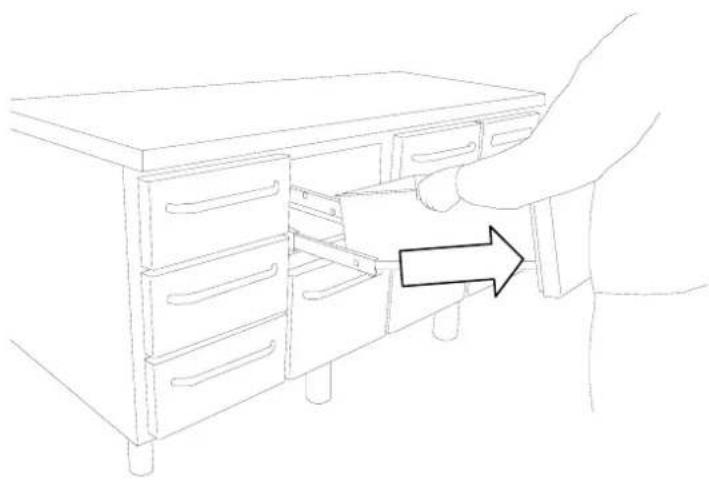
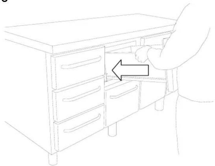
Cleaning of counters with drawers:
If the counter is equipped with drawers and the bottom, sides or back wall require cleaning, the drawers can be removed as follows:
Pull out the drawer. Lift it up, after which the drawer can be pulled of the extension rails (Illustration 1A, 1B, 1C)
After cleaning, the drawer can be replaced. Place the drawer on the outer wheels on the telescopic rails. Lower the drawer into a horizontal position after which it can be pushed into a closed position. The drawer is now securely positioned.
Changing door hinge side
The door can be changed from righthand-hinged to lefthand-hinged or vice-versa.
To do so, proceed as follows:
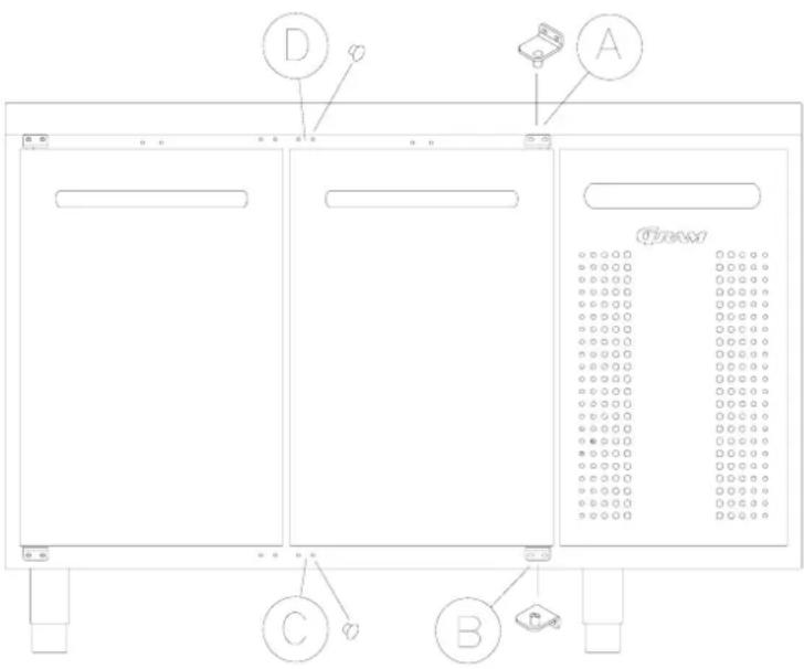
- Remove the hinge at pos. A.
- Lift off the door.
- Remove the hinge at pos. B.
- Move cover plugs in the cabinet from pos. D to pos. A and from pos. C to pos. B.
- Move the cover plug in the door from pos. D to pos. A, too.
- The hinge previously mounted at pos. A is now mounted at pos. C.
- The door is now placed at the hinge at pos. C.
- The hinge previously mounted at pos. B is now mounted at pos. D and adjusted, so that the door is closing properly. Then tighten the screws.
Service
The refrigeration system and the hermetically sealed compressor require no maintenance. However the condenser and air filter requires regular cleaning.
If refrigeration fails, first look to see whether the counter has been unintentionally switched off, or whether a fuse has blown. If the cause of failure cannot be found, contact your supplier quoting TYPE, PART NO and SER. NO of the counter. This information can be found on the nameplate.
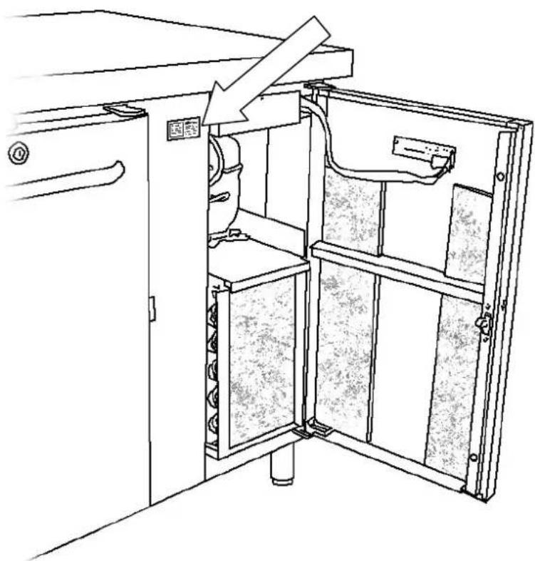
Placement of the nameplate:
natural_image
Technical line drawing of an open industrial machine with internal components and a directional arrow indicating motion (no text or symbols)Disposal
If the counter is to be disposed of, please do so in an environmentally correct way. There are special requirements/conditions to be observed.
DEUTSCH
natural_image
Technical line drawing of a mechanical or electrical cabinet with internal components and a directional arrow indicating motion (no text or symbols)Entsorgung
natural_image
Technical line drawing of a mechanical device with internal components and a directional arrow (no text or symbols)Enlèvement
natural_image
Technical line drawing of an open industrial machine with internal components and a directional arrow indicating flow (no text or symbols)Vernietigen
natural_image
Technical line drawing of a mechanical or electrical cabinet with internal components and a directional arrow (no text or symbols)Utbyte av skåp
natural_image
Line drawing of a person opening a cabinet with an arrow indicating direction (no text or symbols)1B
natural_image
Line drawing of a hand inserting a file into a cabinet drawer with an arrow indicating direction (no text or symbols)1C
natural_image
Line drawing of a person opening a cabinet with drawers, showing a hand interacting with the cabinet (no text or symbols present)Gram Deutschland GmbH. Gram Nederland B.V. Gram (UK) Ltd.
Holztorstraße 60
31157 Sarstedt
Tel.: 050-66 60 46 - 0
Fax: 050-66 60 46 - 49
Twentepoort West 62
Postbus 601
7906 RD Almelo
Tel.: 0546 454252
Fax: 0546 813455
e-mail: info@gram.nl
2 The Technology Centre
London Road, Swanley
Kent BR 8 7AG
Tel.: 01322 616900
Fax: 01322 616901
e-mail: info@gramuk.co.uk
Gram Commercial NUF
P.b. 44 Box 5157
1970 Hemnes, Norway 217 24 Malmö, Sweden
Tel.: 22 88 17 50
Fax: 22 88 17 51
Gram Commercial
Tel.: 040-987848
Fax: 040-987849

Gram Commercial A/S
6500 Vojens - Denmark
Tlf.:+45 73 20 12 00
- GB | Contents
- D
- Inhalt
- NL
- Inhoud
- Bortskaffelse
- Location
- Important!
- Electrical connection
- Warning!
- This counter must be earthed.
- Important
- Starting up
- Servicing:
- Temperature setting
- Temperature control:
- Temperature regulation:
- Error codes on the display
- Temperature alarm
- Potential free alarm relay
- Keylock
- Defrosting
- Defrost water
- Counters with compressor
- Counters connected to a common compressor
- Power failure
- Cleaning
- Always disconnect the counter before cleaning.
- Cleaning of counters with drawers:
- Changing door hinge side
- Service
- Disposal
- DEUTSCH
- Entsorgung
- Enlèvement
- Vernietigen
- Utbyte av skåp
- Gram Deutschland GmbH. Gram Nederland B.V. Gram (UK) Ltd.
- Gram Commercial NUF
- Gram Commercial
Brand : GRAM
Model : GASTRO M 1808 CSG A DL DR C2 U
Category : Fridge