4975 - Measuring equipment PeakTech - Free user manual and instructions
Find the device manual for free 4975 PeakTech in PDF.


User questions about 4975 PeakTech
0 question about this device. Answer the ones you know or ask your own.
Ask a new question about this device
Download the instructions for your Measuring equipment in PDF format for free! Find your manual 4975 - PeakTech and take your electronic device back in hand. On this page are published all the documents necessary for the use of your device. 4975 by PeakTech.
USER MANUAL 4975 PeakTech
Emission: 0 -1 variabel
This product complies with the requirements of the following directives of the European Union for CE conformity: 2014/30/EU (electromagnetic compatibility), 2011/65/EU (RoHS).
We herewith confirm that this product meets the essential protection standards, which are given in directions of council for adaptation of the administration regulations for UK of Electromagnetic Compatibility Regulations 2016 and the Electrical Equipment (safety) regulations 2016.
UK CA CE
Damages resulting from failure to observe the following safety precautions are exempt from any legal claims whatever.
- do not subject the equipment to direct sunlight, extreme temperatures, extreme humidity or dampness
- use extreme caution when the laser beam is turned ON
- do not let the beam enter your eye, another person's eye or the eye of an animal
- be careful not to let the beam on a reflective surface strike your eye
- do not allow the laser light beam impinge on any gas which can explode
- do not let the beam of any body
- do not operate the equipment near strong magnetic fields (motors, transformers etc.)
- do not subject the equipment to shocks or strong vibrations
- keep hot soldering iron or guns away from the equipment
- allow the equipment to stabilise at room temperature before taking up measurement (important for exact measurement)
- do not modify the equipment in any way
- opening the equipment and service- and repair work must only be performed by qualified service personnel
Cleaning the cabinet
Clean only with a damp soft cloth and a commercially available mild household cleanser. Ensure that no water gets inside the equipment to prevent possible shorts and damage to the equipment.
2. Features
This infrared-thermometer meets ANSI S1.4 and IEC 651 Type 2 standards.
- Precise non-contact measurements
- Switchable C/F temperature units
- Auto power off
- Automatic data-hold
- Backlight LCD Display (blue, red at alarm)
- Laser target pointer (2-point laser)
- Auto-ranging
- Adjustable emissivity factor
- Trigger lock
3. Front Panel description
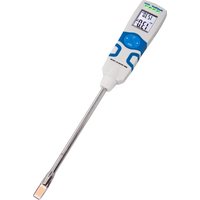
PeakTech® 4975:
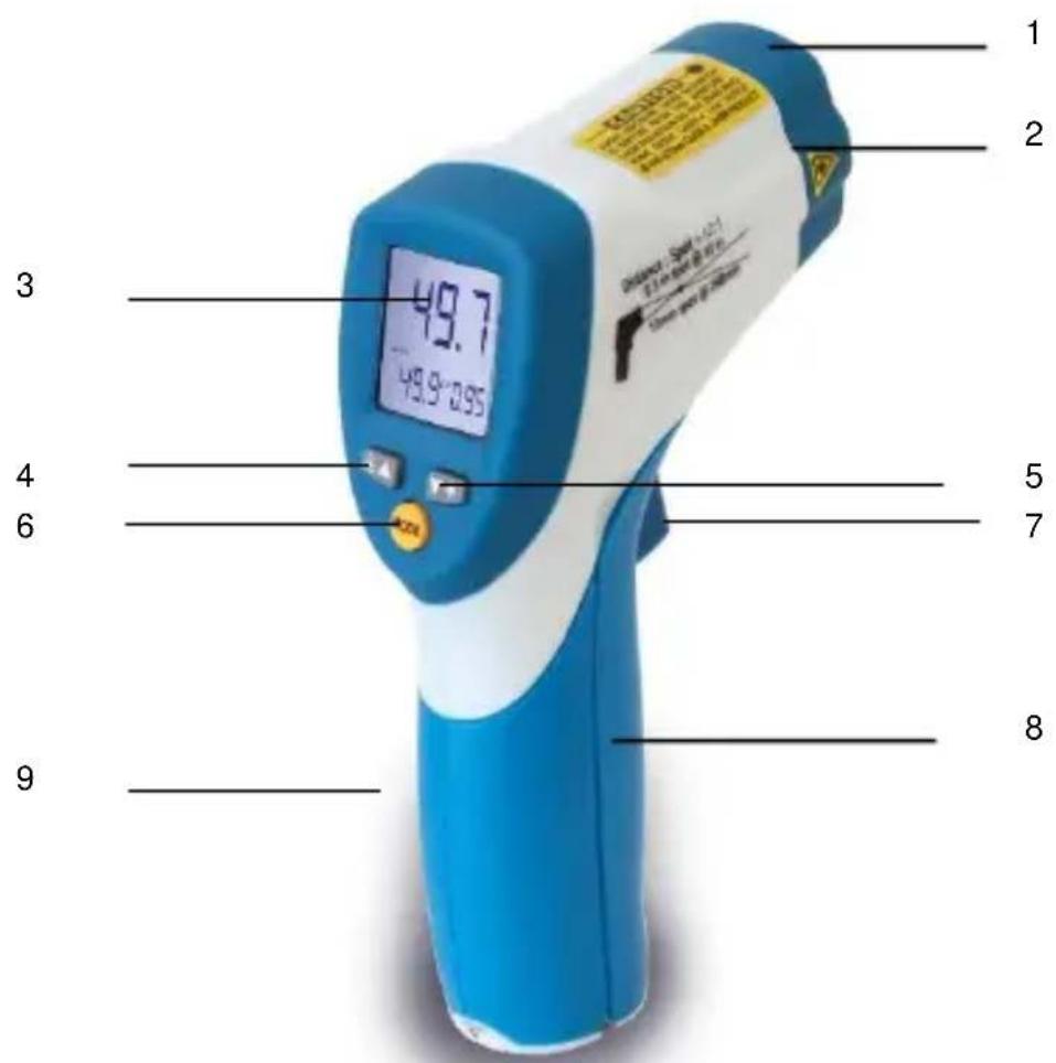
- IR Sensor
- 2-point laser pointer beam
- LCD - Display
4.up button - down button
- MODE button
- ON/HOLD key
- Battery cover
- Handle grip
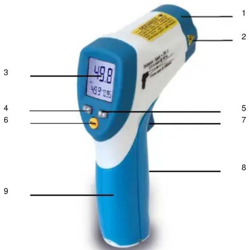
- IR Sensor
- 2-point laser pointer beam
- LCD - Display
4.up button - down button
- MODE button
- ON/HOLD key
- Battery cover
- Handle grip
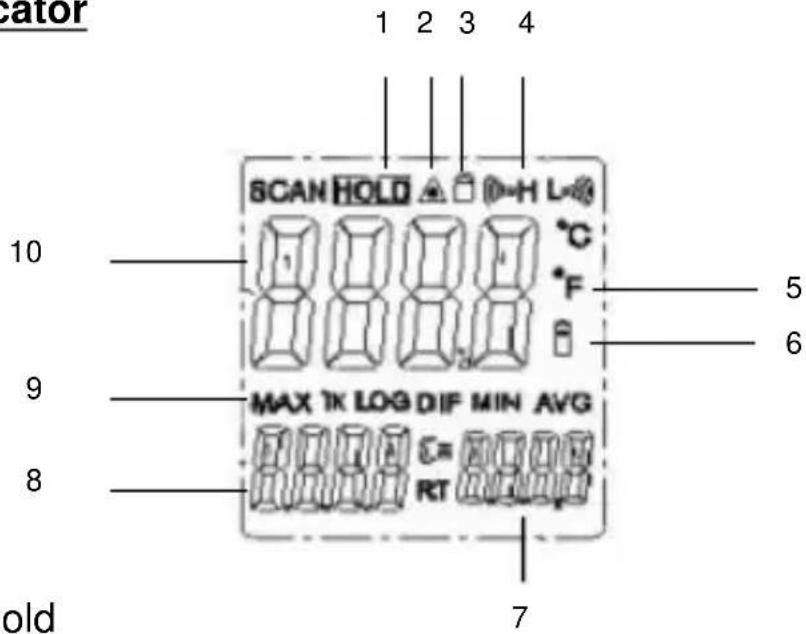
3.1. Indicator
- Data hold
- Laser " on" symbols
3 Lock symbol - High alarm and low alarm symbol
- ^ C/^ F symbol
- Low power symbols
- Emissivity symbol and value
- Temperature values for the MAX
- Symbols for MAX
- Current temperature value
4. Measurement Considerations
Holding the meter by its handle, point the IR sensor toward the object whose temperature is to be measured.
The meter automatically compensates for temperature deviations from ambient temperature. Keep in mind that it will take up to 30 minutes to adjust to wide ambient temperature changes. When low temperatures are to be measured followed by high temperature measurements some time (several minutes) is required after the low (and before the high) temperature measurements are made.
This is a result of the cooling process which must take place for the IR sensor.
5. Non-Contact IR Measurement Operation
5.1. Power ON/OFF
-
Press the ON/HOLD key to take a reading. Read the measured temperature on the LCD.
-
The meter powers OFF automatically approximately 7 seconds after the ON/HOLD key is released.
5.2. Selecting Temperature units
Select the required temperature unit by opening the battery compartment (see point 7) and switchover the slide-switch, which is installed.
^ C is selected by manufacturer.
5.3. Data Hold
This meter automatically holds the last temperature reading on the LCD for 7 seconds after the ON/HOLD key is released.
No extra key presses are necessary to freeze the displayed reading.
5.4. Backlite LCD
Select backlite by first pressing the ON/HOLD key and then pressing the BACKLITE (5) key. Press the backlight key again to turn the backlight OFF.
5.5. Laser Pointer
- To turn the laser pointer ON, press the LASER (4) key after pressing the ON/HOLD key
- Press the Laser key again to turn OFF the laser.
Function
- While measuring (triggered ON-key) use the UP and DOWN keys to adjust the Emissivity.
- In the hold time (On-key not triggered), use the UP key to turn on or off and the DOWN key to turn on or off the backlight
- To set values for the High Alarm (HAL), Low Alarm (LAL) and Emissivity (EMS), press the MODE button until the appropriate code appears in the display, press the UP and DOWN buttons to adjust the desired values.
MODE Button Function
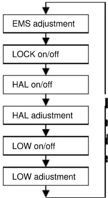
Pressing the mode button with released ON-key also allows you to access the set
state, Emissivity(EMS), Lock on/off, HAL on/off, HAL adjustment, LOW on/off,
LOW adjustment.
Each time you press set you advance through the mode cycle.
The diagram shows the sequence of functions in the mode cycle.
EMS adjustment.
The Emissivity(EMS) is digitally adjustable from 0.10 to 1.0. Press the UP and
DOWN-keys to raise or lower the EMS.
LOCK function
The lock mode is particularly useful for continuous monitoring of temperatures
without pressing the ON-key during the measurement.
Press the UP or DOWN key to turn on/off. Press the Measurement Trigger to
Confirm the locked measurement mode. The IR Thermometer will continuously
display the measured temperature until you press again the ON-key.
In lock mode, press the UP or DOWN keys to adjust the Emissivity.
HIGH (HAL) / LOW (LAL)- Alarm
Press the up button or down button to turn HAL/LAL on or off. Press the
Measurement Trigger to confirm the High/Low alarm mode.
After switching on or off the HAL/LAL, press the SET-key to switch to the
alarm-value setting.
Use the UP or DOWN-key to set the desired value for HAL or LAL.
When HAL or LAL is activated the backlight will flash in red color and A warning noise will sound.
This unit is equipped with a visual alarm.
If during a measurement, the measured temperature exceeds the preset "high alert" temperature, the backlight will flash with red LED. The same behavior shows the device when the measured temperature is lower than the preset "low alarm" temperature.
"High Alert" resp. "Low Alarm" to preset and must be enabled.
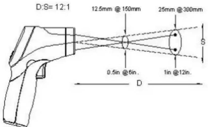
5.6 Description of the IR-Sensor
PeakTech® 4975:
PeakTech® 4980:
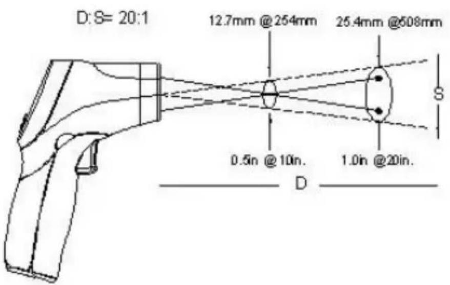
D = Distance (avoid exposure-laser radiation is emitted from this aperture) approx. 12:1 / 20:1
S = diameter of the IR-sensor beam
6. Technical Specifications
| Display | 3½-digit, LCD-Display with backlight |
| Range | |
| P 4975 | -50°C...650°C (-58°F...1202°F) |
| P 4980 | -50°C...800°C (-58°F...1472°F) |
| Sample rate | approx. 6 x/Sec. (150ms) |
| Power off | automatic shutoff after 7 seconds |
| Resolution | 0,1°C/F, 1°C/F |
| Emissivity setting | 0,1 ~ 1,0 adjustable |
| Spectral response | 8 ... 14 μm |
| Laser product | class 2, Output < 1mW, Wave length: 630 - 670 nm |
| Distance Factor D/S (distance/spot) | |
| P 4975 | 12:1 |
| P 4980 | 20:1 |
| Operating temperature | 0 ... 50 °C / 32 ... 122 °F |
| Operating humidity | 10% - 90% |
| Power Supply | 9 V battery |
| Dimensions (WxHxD) | 42 x 155 x 95 mm |
| Weight | 180 g |
PeakTech® 4975:
| Range (autom. Selection 0,1°C/1°C) | Resolution | Accuracy | |
| -50.0°C to 300°C | -50°C - +20°C | 0,1°C | ±2,5°C |
| +20°C-300°C | ±1,0% rdg.. ±2°C | ||
| 201°C to 650°C | 1°C | ±-1,5% rdg. | |
| Range (autom. Selection 0,1°F/1°F) | Resolution | Accuracy | |
| -58.0°F to 572°F | -58°F - +68°F | 0,1°F | ±4,5°F |
| +68°F-572°F | ±1,0% rdg.. ±2,8°F | ||
| 572°F to1202°F | 1°F | ±1,5% rdg. | |
PeakTech® 4980:
| Range (autom. Selection 0,1°C/1°C) | Resolution | Accuracy | |
| -50.0°C to 300°C | -50°C - +20°C | 0,1°C | ±2,5°C |
| +20°C-300°C | ±1,0% rdg.. ±2°C | ||
| 300°C to 800°C | 1°C | ±1,5% rdg. | |
| Range (autom. Selection 0,1°C/1°C) | Resolution | Accuracy | |
| -58.0°F to 572°F | -58°F- +68°F | 0,1°F | ±4,5°F |
| +68°F-572°F | ±1,0% rdg. ±2,8°F | ||
| 572°F to 1472°F | 1°F | ±1,5% rdg. | |
Note: Accuracy is given at 18^ to 28^ (64°F to 82°F), less than 80% R. H.
Emissivity: 0 - 1 variable
Field of view: Make sure, that the target is larger than the unit's spot size. The smaller the target, the closer you should be to it. When accuracy is critical, make sure, that the target is at least twice as large as the spot size.
7. Battery Replacement
A Bat Symbol in the display is the indication that the battery voltage has fallen into the critical region (6,5 to 7,5 V). Reliable readings can be obtained for several hours after the first appearance of the low battery indication.
Open the battery compartment (see picture below) and remove the battery, then install a new battery and replace the cover.
ATTENTION!
Batteries, which are used up dispose duly. Used up batteries are hazardous and must be given in the for this supposed collective container.

Notification about the Battery Regulation
The delivery of many devices includes batteries, which for example serve to operate the remote control. There also could be batteries or accumulators built into the device itself. In connection with the sale of these batteries or accumulators, we are obliged under the Battery Regulations to notify our customers of the following:
Please dispose of old batteries at a council collection point or return them to a local shop at no cost. The disposal in domestic refuse is strictly forbidden according to the Battery Regulations. You can return used batteries obtained from us at no charge at the address on the last side in this manual or by posting with sufficient stamps.
Contaminated batteries shall be marked with a symbol consisting of a crossed-out refuse bin and the chemical symbol (Cd, Hg or Pb) of the heavy metal which is responsible for the classification as pollutant:
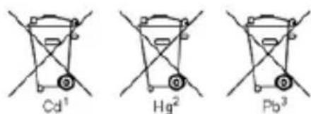
- "Cd" means cadmium.
- "Hg" means mercury.
- "Pb" stands for lead.
You can obtain further information about the Battery Regulations from the Bundesministerium für Umwelt, Naturschutz und
Reaktorsicherheit (Federal Ministry of Environment, Nature Conservation and Reactor Safety).
8. How it Works
Infrared thermometers measure the surface temperature of an object. The unit's optics sense emitted, reflected and transmitted energy, which is collected and focused onto a detector. The unit's electronics translate the information into a temperature reading which is displayed on the unit. In units with a laser, the laser is used for aiming purposes only.
8.1. Field of View
Make sure that the target is larger than the unit's spot size. The smaller the target, the closer you should be to it. When accuracy is critical, make sure the target is at least twice as large as the spot size.
8.2. Distance & Spot Size
As the distance (D) from the object increases, the spot size (S) of the area measured by the unit becomes larger. See Fig. 2
8.3. Locating a hot Spot
To find a hot spot aim the thermometer outside the area of interest, then scan across with an up and down motion until you locate hot spot.
Reminders
- The unit cannot measure through transparent surfaces such as glass. It will measure the surface temperature of the glass instead.
- Steam, dust, smoke, etc. can prevent accurate measurement by obstructing the unit's optics.
8.4 Emissivity
Most (90 % of typical applications) organic materials and painted or oxidised surfaces have an emissivity of 0,95. Inaccurate readings will result from measuring shiny or polished metal surfaces. To compensate, cove the surface to be measured with masking tape or flat black paint. Allow time for the tape to reach the same temperature as the material underneath it. Measure the temperature of the tape or painted surface.
| Material | Condition | Temperature-Range | Emissivity-factor (ε) |
| Aluminium | polished | 50°C ... 100°C | 0.04 ... 0.06 |
| Raw surface | 20°C ... 50°C | 0.06 ... 0.07 | |
| oxidized | 50°C ... 500°C | 0.2 ... 0.3 | |
| Aluminium oxide, Aluminium powder | normal Temperature | 0.16 | |
| Brass | matt | 20°C ... 350°C | 0.22 |
| oxidized at 600°C | 200°C ... 600°C | 0.59 ... 0.61 | |
| Polished | 200°C | 0.03 | |
| Wrought with sandpaper | 20°C | 0.2 | |
| Bronze | polished | 50°C | 0.1 |
| porous and raw | 50°C ... 150°C | 0.55 | |
| Chrome | polished | 50°C 500°C ... 1000°C | 0.1 0.28 ... 0.38 |
| Copper | burnished | 20°C | 0.07 |
| elektrolytic polished | 80°C | 0.018 | |
| elektrolytic powdered | normal Temperature | 0.76 | |
| molten | 1100°C ... 1300°C | 0.13 ... 0.15 | |
| oxidized | 50°C | 0.6 ... 0.7 | |
| oxidized and black | 5°C | 0.88 | |
| Iron | With red rust | 20°C | 0.61 ... 0.85 |
| elektrolytic polished | 175°C ... 225°C | 0.05 ... 0.06 | |
| Wrought with sandpaper | 20°C | 0.24 | |
| oxidized | 100°C 125°C ... 525°C | 0.74 0.78 ... 0.82 | |
| Hot-rolled | 20°C | 0.77 | |
| Hot-rolled | 130°C | 0.6 | |
| Laquer | Bakelite | 80°C | 0.93 |
| black, matt | 40°C ... 100°C | 0.96 ... 0.98 | |
| black, high-glossed, sprayed onto iron | 20°C | 0.87 | |
| Heat-resistant | 100°C | 0.92 | |
| white | 40°C ... 100°C | 0.80 ... 0.95 | |
| Lamp black | - | 20°C ... 400°C | 0.95 ... 0.97 |
| Application to solid surfaces | 50°C ... 1000°C | 0.96 | |
| With water glass | 20°C ... 200°C | 0.96 | |
| Paper | black | normal Temperature | 0.90 |
| Paper | black, matt | dto. | 0.94 |
| green | dto. | 0.85 | |
| Red | dto. | 0.76 | |
| White | 20°C | 0.7 ... 0.9 | |
| yellow | normal Temperature | 0.72 | |
| Glass | - | 20°C ... 100°C 250°C ... 1000°C 1100°C ... 1500°C | 0.94 ... 0.91 0.87 ... 0.72 0.7 ... 0.67 |
| Matted | 20°C | 0.96 | |
| Gypsum | - | 20°C | 0.8 ... 0.9 |
| Ice | Covered with heavy frost | 0°C | 0.98 |
| smooth | 0°C | 0.97 | |
| Lime | - | normal Temperature | 0.3 ... 0.4 |
| Marble | greyish polished | 20°C | 0.93 |
| Glimmer | Thick layer | normal Temperature | 0.72 |
| Porcelain | glazed | 20°C | 0.92 |
| White, glossy | normal Temperature | 0.7 ... 0.75 | |
| Rubber | Hard | 20°C | 0.95 |
| Soft, grey rough | 20°C | 0.86 | |
| Sand | - | normal Temperature | 0.6 |
| Shellac | black, matt | 75°C ... 150°C | 0.91 |
| black, glossy, applied to tin alloy | 20°C | 0.82 | |
| Plumbum | grey, oxidized | 20°C | 0.28 |
| at 200°C oxidized | 200°C | 0.63 | |
| red, powder | 100°C | 0.93 | |
| Plumbum | Lead sulfate, Powder | normal temperature | 0.13 ... 0.22 |
| Quecksilber | pure | 0°C ... 100°C | 0.09 ... 0.12 |
| Molybdenum | - | 600°C ... 1000°C | 0.08 ... 0.13 |
| Heating wire | 700°C ... 2500°C | 0.10 ... 0.30 | |
| Chrome | wire, pure | 50°C | 0.65 |
| 500°C ... 1000°C | 0.71 ... 0.79 | ||
| wire, oxidized | 50°C ... 500°C | 0.95 ... 0.98 | |
| Nickel | absolutely pure, polished | 100°C | 0.045 |
| 200°C ... 400°C | 0.07 ... 0.09 | ||
| at 600°C oxidized | 200°C ... 600°C | 0.37 ... 0.48 | |
| wire | 200°C ... 1000°C | 0.1 ... 0.2 | |
| Nickel oxidized | 500°C ... 650°C | 0.52 ... 0.59 | |
| 1000°C ... 1250°C | 0.75 ... 0.86 | ||
| Platinum | - | 1000°C ... 1500°C | 0.14 ... 0.18 |
| Pure, polished | 200°C ... 600°C | 0.05 ... 0.10 | |
| Stripes | 900°C ... 1100°C | 0.12 ... 0.17 | |
| wire | 50°C ... 200°C | 0.06 ... 0.07 | |
| 500°C ... 1000°C | 0.10 ... 0.16 | ||
| Silver | Pure, polished | 200°C ... 600°C | 0.02 ... 0.03 |
| Steel | Alloy (8% Nickel, 18% Chrome) | 500°C | 0.35 |
| Galvanized | 20°C | 0.28 | |
| oxidized | 200°C ... 600°C | 0.80 | |
| strongly oxidized | 50°C | 0.88 | |
| 500°C | 0.98 | ||
| Newly-rolled | 20°C | 0.24 | |
| Rough, flat surface | 50°C | 0.95 ... 0.98 | |
| rusty, redt | 20°C | 0.69 | |
| sheet | 950°C ... 1100°C | 0.55 ... 0.61 | |
| sheet, Nickel-coated | 20°C | 0.11 | |
| sheet, polished | 750°C ... 1050°C | 0.52 ... 0.56 | |
| Steel | sheet, rolled | 50°C | 0.56 |
| rustless, rolled | 700°C | 0.45 | |
| rustless, sand-blasted | 700°C | 0.70 | |
| Cast Iron | poured | 50°C | 0.81 |
| 1000°C | 0.95 | ||
| liquid | 1300°C | 0.28 | |
| at 600°C oxidized | 200°C ... 600°C | 0.64 ... 0.78 | |
| polished | 200°C | 0.21 | |
| Tin | burnish | 20°C ... 50°C | 0.04 ... 0.06 |
| Titanium | at 540°C oxidized | 200°C | 0.40 |
| 500°C | 0.50 | ||
| 1000°C | 0.60 | ||
| polished | 200°C | 0.15 | |
| 500°C | 0.20 | ||
| 1000°C | 0.36 | ||
| Wolfram | - | 200°C | 0.05 |
| 600°C ... 1000°C | 0.1 ... 0.16 | ||
| Heating wire | 3300°C | 0.39 | |
| Zinc | at 400°C oxidized | 400°C | 0.11 |
| oxidized surface | 1000°C ... 1200°C | 0.50 ... 0.60 | |
| Polished | 200°C ... 300°C | 0.04 ... 0.05 | |
| sheet | 50°C | 0.20 | |
| Zirconium | Zirconium oxide, Powder | normal temperature | 0.16 ... 0.20 |
| Zirconium silicate, Powder | normal temperature | 0.36 ... 0.42 | |
| Asbestos | tablet | 20°C | 0.96 |
| Paper | 40°C ... 400°C | 0.93 ... 0.95 | |
| Powder | normal temperature | 0.40 ... 0.60 | |
| slate | 20°C | 0.96 | |
| Coal | Heating wire | 1000°C ... 1400°C | 0.53 |
| cleaned (0.9% Asche) | 100°C ... 600°C | 0.81 ... 0.79 | |
| Cement | - | normal temperature | 0.54 |
| Charcoal | Powder | normal temperature | 0.96 |
| Clay | Fired clay | 70°C | 0.91 |
| Fabric (Cloth) | black | 20°C | 0.98 |
| Vulcanite | - | normal temperature | 0.89 |
| Grease | coarse | 80°C | 0.85 |
| Silicon | Granulate powder | normal temperature | 0.48 |
| Silicon, Powder | normal temperature | 0.30 | |
| Slag | furnace | 0°C ... 100°C | 0.97 ... 0.93 |
| 200°C ... 1200°C | 0.89 ... 0.70 | ||
| Snow | - | - | 0.80 |
| Stucco | rough, burned | 10°C ... 90°C | 0.91 |
| Bitumen | Waterproof paper | 20°C | 0.91 ... 0.93 |
| Water | Layer on metal surface | 0°C ... 100°C | 0.95 ... 0.98 |
| Brick | Chamotte | 20°C | 0.85 |
| 1000°C | 0.75 | ||
| 1200°C | 0.59 | ||
| Fire-resistant | 1000°C | 0.46 | |
| Fire-resistant, high-blasted | 500°C ... 1000°C | 0.80 ... 0.90 | |
| Fire-resistant, low-blasted | 500°C ... 1000°C | 0.65 ... 0.75 | |
| Silicon (95% SiO2) | 1230°C | 0.66 |
All rights, also for translation, reprinting and copy of this manual or parts are reserved.
Reproduction of all kinds (photocopy, microfilm or other) only by written permission of the publisher.
This manual considers the latest technical knowing. Technical changing which are in the interest of progress reserved.
We herewith confirm, that the units are calibrated by the factory according to the specifications as per the technical specifications. We recommend to calibrate the unit again, after 1 year.
PeakTech®
1 in = 2,5 cm 6 in = 15 cm
2 in = 5 cm 12 in = 30 cm
4 in = 10 cm 24 in = 60 cm
Emission: 0 -1 variable