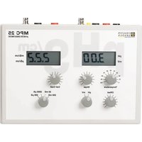
MPC 25 - Measuring equipment CHAUVIN ARNOUX - Free user manual and instructions
Find the device manual for free MPC 25 CHAUVIN ARNOUX in PDF.


User questions about MPC 25 CHAUVIN ARNOUX
0 question about this device. Answer the ones you know or ask your own.
Ask a new question about this device
Download the instructions for your Measuring equipment in PDF format for free! Find your manual MPC 25 - CHAUVIN ARNOUX and take your electronic device back in hand. On this page are published all the documents necessary for the use of your device. MPC 25 by CHAUVIN ARNOUX.
USER MANUAL MPC 25 CHAUVIN ARNOUX
text_image
Made in France3. UTILISATION
3.1 BRANCHEMENT ET MISE EN MARCHE
You have just puchased a MPC 25 pH meter / Conductimeter, and we thank you.
For best results with your device:
- Read these operating instructions carefully,
- Observe the precautions of use.
MEANINGS OF THE SYMBOLS USED
 | WARNING, risk of DANGER! The operator must refer to this user's manual whenever this danger symbol appears. |
 | The CE marking indicates conformity with European directives, in particular LVD and EMC. |
 | The rubbish bin with a line through it indicates that, in the European Union, the product must undergo selective disposal in compliance with Directive WEEE 2002/96/EC. This equipment must not be treated as household waste. |
CONTENTS
- TECHNICAL SPECIFICATIONS ......20
- DESCRIPTION OF THE INSTRUMENT....21
2.1 TOP 21
2.2 REAR PANEL 22
2.3 BOTTOM 22 - USE 23
3.1 CONNECTION AND STARTING UP 23
3.2 ADJUSTMENT AND MEASUREMENT OF THE pH 23
3.2.1 MANUAL TEMPERATURE CORRECTION....23
3.2.2 CALIBRATION AND ADJUSTMENT OF THE PH SCALE: 23
3.3 MEASUREMENT OF POTENTIALS: 24
- PRINCIPLE OF THE CONDUCTIVITY MEASUREMENT ......26
4.1 CHARACTERISTICS OF THE MEASUREMENT CELL: 26
4.2 CALIBRATING THE MEASUREMENT SYSTEM: 27
4.3 DETERMINING THE CELL COEFFICIENT:....27
4.4 ADJUSTMENT AND MEASUREMENT OF THE CONDUCTIVITY 27
4.5 TABLE: CONDUCTIVITY OF POTASSIUM CHLORIDE SOLUTIONS .....28
4.5.1 CONDUCTIVITY VS. TEMPERATURE 28
4.5.2 CONDUCTIVITY OF REFERENCE SOLUTIONS OF POTASSIUM CHLORIDE AT 20°C....29
- RECORDER OUTPUT ...... 29
- VARIOUS POSSIBLE PROBLEMS....30
- SAFETY RULES ......31
- MAINTENANCE....32
8.1 CLEANING....32
8.2 METROLOGICAL CHECK....32
8.3 REPAIRS....32 - TO ORDER....33
9.1 DELIVERY CONDITION....33
1. TECHNICAL SPECIFICATIONS
| 2000-point liquid crystal display | |
| Ranges: | |
| pH | 0,00 to 14,00 pH |
| mV | -1999 to + 1999mV |
| Conductivity | 0-200mS/cm, 0-20mS/cm, 0-2000μS/cm, 0-200μS/cm |
| Voltage across the terminals of the conductivity cell. | 100mV / 680Hz |
| Accuracy ± 1% | |
| Manual temperature compensation ( for the pH) | 0 to 100°C |
| Temperature of use | 0 to 50°C |
| Maximum altitude 2000m | |
| Humidity | 5 to 80% at 35°C |
| Pollution class | Category 2 |
| Category of use 2 | |
| COMPLIANCE WITH STANDARDS: | |
| Safety | With the power supply provided:EN 61010-1.Normal environmental conditions (indoor use) |
| CEM EN 61326, class B instrument, intermittent operation. | |
| Consumption 0,5W | |
| Dimensions | 275 x 208 x 51 mm |
| Weight 800g | |
The MPC 25 is provided with a power supply unit.
| Power supply | 230V – 50/60Hz |
| Output 9V | —— |
2. DESCRIPTION OF THE INSTRUMENT
2.1 TOP

CHAUVIN ARNOUX
CHAUVIN ARNOLX GROUP
text_image
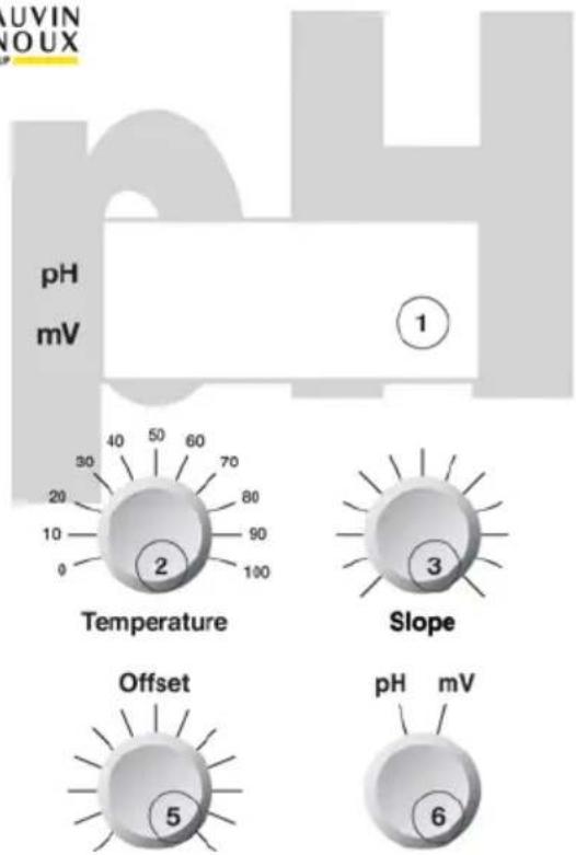
pH mV Temperature Slope Offset pH mV 1 2 3 4 5 6MPC 25
pH METER CONDUCTIMETER
text_image
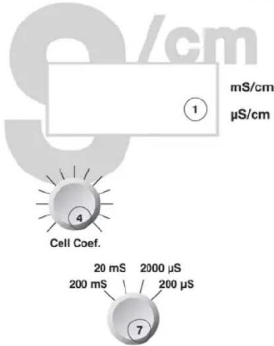
mS/cm μS/cm 1 4 Cell Coef. 20 mS 2000 μS 200 mS 200 μS 7- Liquid crystal display units
- Temperature adjustment knob
- Scale adjustment knob
- Cell coefficient adjustment knob
- Calibration adjustment knob
- pH/mV switch
- 4-position range switch
2.2 REAR PANEL

text_image
Conductivity Cell - Recorder Output + Conductivity pH/mV Electrode Reference - Recorder Output + pH/mV Power 6 1 2 7 8 3 4 5- Black ⊖ - Insulated 4mm terminal for conductivity recorder output
- Red ⊕ - Insulated 4mm terminal for conductivity recorder output
- Black ⊖ Insulated 4mm terminal for pH/mV recorder output
- Red ⊕ Insulated 4mm terminal for pH/mV recorder output
- Connector for the power supply unit
- BNC connector for conductivity cell
- BNC connector for pH/mV electrode
- Input for separate reference electrode
2.3 BOTTOM
Identification label.

text_image
Made in France3. USE
3.1 CONNECTION AND STARTING UP
Unpack the instrument, the power supply unit, the solutions, and the operating manual.
pH/mV measurement:
Connect the combined pH electrode or another combined electrode to the "Electrode" connector (BNC connector on the back of the instrument).
With the separate electrodes, connect the glass or metal electrode to the "Electrode" jack and the reference electrode to the yellow terminal.
Conductivity measurement:
Connect the conductivity cell to the "Conductivity cell" connector (BNC connector on the back of the instrument).
Finally, connect the power supply unit to the "Power" connector.
(The MPC 25 must be used only with the power supply unit provided).
3.2 ADJUSTMENT AND MEASUREMENT OF THE pH
Set the switch to pH.
3.2.1 MANUAL TEMPERATURE CORRECTION
Note the temperature of the sample to be analyzed.
Set the mark on the "Temperature" knob to the temperature of the medium to be analyzed or of the buffer solution.
Remark: Ideally, the buffer solutions used to calibrate the measurement system (pH meter-electrode) should be at this same temperature.
3.2.2 CALIBRATION AND ADJUSTMENT OF THE pH SCALE:
3.2.2.1 Checks/precautions concerning the electrodes:
Before each pH measurement operation, make sure that:
the glass bulb of the electrode does not contain any air bubble,
the liquid electrolyte reference electrode is correctly filled with a potassium chloride solution of the right concentration (KCl, 1 mol.L ^-1 ),
the plug of the filling orifice of the reference electrode is open,
the electrodes are correctly connected.
3.2.2.2 Calibration
Example: Use of pH4 and pH7 buffer solutions.
➢ Rinse the combined pH electrode (or the two separate electrodes) in distilled water.
➢ Immerse the electrode in the pH7 buffer solution (always first).
When the signal stabilizes, use the "Offset" knob to adjust the value displayed to 7.00
➢ Rinse the electrode in distilled water.
- Immerse the electrode in a pH4 buffer solution.
When the signal stabilizes, use the "Slope" knob to adjust the reading to 4.00
➢ Rinse the electrode in distilled water.
- Immerse the electrode in the medium to be analyzed.
3.3 MEASUREMENT OF POTENTIALS:
Set the switch to mV.
Example: Use of the Michaelis solution.
Composition of the solution: KCI
$$ \mathrm{K} _ {3} \left[ \mathrm{F} _ {\mathrm{e}} (\mathrm{CN}) _ {6} \right] $$
$$ \mathsf {K} _ {4} \left[ \mathsf {F} _ {\mathrm{e}} (\mathsf {C N}) _ {6} \right] $$
ATTENTION: do not acidify.
Electrochemical couple involved: [F_e(CN)6]^3- + 1 [Fe(CN)_6]^4-
The oxidation-reduction potential E of a solution is equal to the potential read (E read) plus the potential of the reference electrode (E ref).
For a reference electrode (Ag, AgCl, KCl 1 mol.L ^-1 ) E ref = 236mV at 25°C (Cf. table on p 9).
For Michaelis reference solution, E = 382mV.
Therefore E read = 382 - 236 = 146mV.
➢ Rinse the combined electrode or the separate electrodes (for example: a platinum electrode and a reference electrode) in distilled water.
- Immerse the electrode in the Michaelis solution.
Use the "Offset" knob to adjust the display to +146 if necessary.
➢ Rinse the electrode in distilled water.
- Immerse the electrode in the medium to be analyzed.
If the work is done at a temperature other than 25^ C or with a reference electrode other than (Ag, AgCl, 1 mol. L^-1 KCl), the potential E read will be different from that indicated on the label. Here is the table applicable to the Michaelis solution:
POTENTIAL DIFFERENCE BETWEEN THE PLATINUM ELECTRODE AND THE REFERENCE ELECTRODE IMMERSED IN THE DILUTED MICHAELIS SOLUTION (see label)
| Reference electrode Temperature | (Ag, AgCl, KCl, 1mol.L-1) | (Ag, AgCl, KCl, 3mol.L-1) | (Ag, AgCl, KCl, 3,5mol.L-1) | (Ag, AgCl, KCl, full) | (Hg, Hg2, Cl2KCl 1mol.L-1) | (Hg, Hg2, Cl2KCl full) | (Hg, Hg2, SO4K2SO41mol.L-1) |
| 15°C | 164mV | 192mV | 195mV | 198mV | 121mV | 156mV | |
| 20°C | 155mV | 183mV | 187mV | 191mV | 111mV | 147mV | |
| 25°C | 146mV | 174mV | 177mV | 183mV | 99mV | 138mV | -276mV |
| 30°C | 135mV | 165mV | 168mV | 175mV | 87mV | 128mV | |
| UNCERTAINTY | ± 4mV | ± 4mV | ± 4mV | ± 4mV | ± 4mV | ± 4mV | ± 4mV |
4. PRINCIPLE OF THE CONDUCTIVITY MEASUREMENT
The electrical conductance, G, of a liquid depends on the geometry of the volume of liquid involved. It is the reciprocal of the resistance, R. It is expressed in Siemens (S).
$$ \mathbf {G} = 1 / \mathbf {R}; \quad 1 \mathbf {S} = 1 \Omega^ {- 1} $$
The conductivity is reciprocal of the resistivity . It is expressed in Siemens per centimetre. The conductivity is a specific characteristic of a liquid. It is the conductivity of a column of liquid 1cm long having a cross-sectional area of 1cm^2 . The conductivity of an electrolyte depends only on its nature and its concentration.
$$ \gamma = 1 / \rho ; 1 S. c m ^ {- 1} = 1 (\Omega . c m) ^ {- 1} $$
Just as the resistance and the resistivity are related by the formula: R = (I/S)
The conductance and the conductivity are related by the formula: G = (S / l)
Where G conductance in Siemens
$$ \begin{array}{c} \gamma \ S \end{array} \text { conductivity in } S. c m ^ {- 1}. $$
I length in cm.
The conductivity of an electrolyte can be measured simply by maintaining a fixed alternating voltage on the terminals of the cell and measuring the current that flows through it.
4.1 CHARACTERISTICS OF THE MEASUREMENT CELL:
The conductometry cell comprises two square plates (5mm on a side) of platinum-plated platinum, plane, parallel, and 4mm apart. The smooth platinum plates are platinum-plated, in other words covered with platinum dendrites to form a large porous surface area. The purpose of this operation is to limit polarization of the electrodes.
The measured conductance of an electrolytic solution depends not only on the conductivity of the volume of solution exactly between the plates of the sensor, but also on the solution near this cubic volume, because the measurement cell is immersed in a larger volume of solution.
4.2 CALIBRATING THE MEASUREMENT SYSTEM:
In practice, the "cell constant" of the measurement line can be determined only by calibration, by immersing the cell used in a standard solution having a known conductivity at a given temperature (for example: decimolar aqueous solution of potassium chloride).
Since the sensor provided has a cell constant close to unity, a small adjustment using the cell coefficient knob is sufficient to adjust the initial conductance reading to the true conductivity of the reference solution (see tables of conductivity vs. temperature).
The measurement system is then calibrated and gives a direct reading of the conductivity of the medium studied.
4.3 DETERMINING THE CELL COEFFICIENT:
However, if the user wants to determine the true cell constant of an insulated probe, a pure resistance must be used.
First, the conductimeter connected to this pure resistance is adjusted. Then, the probe, connected to the same adjusted instrument, is immersed in the reference solution. The true cell constant of the probe is then found by calculating the ratio of the conductance displayed to the known (measured) conductivity of this reference solution.
$$ \mathbf {G} _ {\text { displayed }} / \gamma_ {\text { reference }} = \text { True cell constant } $$
4.4 ADJUSTMENT AND MEASUREMENT OF THE CONDUCTIVITY
We recommend adjusting the cell using a reference solution in the same range as the solution to be measured.
Example : 0.1 mol.L ^-1 solution of KCl
Set the range switch to: 20mS.
Immerse the cell in the 0.1mol.L ^-1 KCl solution
Use the "Cell coefficient" knob to adjust the display to the value given by the table below as a function of the temperature of the solution.
(example : 12.97mS to 25°C)
Rinse the cell in distilled water.
Immerse the cell in the medium to be analyzed.
4.5 TABLE: CONDUCTIVITY OF POTASSIUM CHLORIDE SOLUTIONS
4.5.1 CONDUCTIVITY VS. TEMPERATURE
| Dilution to 1/10 | Dilution to 1/50 | Dilution to 1/100 | Dilution to 1/1000 | |
| TEMPERATURE °C | KCl 0.1 mol.L^-1 | KCl 0.02 mol.L^-1 | KCl 0.01 mol.L^-1 | KCl 0.001 mol.L^-1 |
| Conductivity mS/cm | Conductivity mS/cm | Conductivity μS/cm | Conductivity μS/cm | |
| 15 | 10.410 | 2.242 | 1,147 | 119.1 |
| 16 | 10.670 | 2.293 | 1,174 | 121.9 |
| 17 | 10.930 | 2.347 | 1,199 | 124.5 |
| 18 | 11.190 | 2.398 | 1,224 | 127.1 |
| 19 | 11.430 | 2.451 | 1,250 | 129.6 |
| 20 | 11.700 | 2.500 | 1,279 | 132.5 |
| 21 | 11.960 | 2.551 | 1,305 | 135.3 |
| 22 | 12.220 | 2.604 | 1,331 | 138.1 |
| 23 | 12.470 | 2.659 | 1,359 | 140.9 |
| 24 | 12.730 | 2.710 | 1,387 | 143.8 |
| 25 | 12.970 | 2.769 | 1,412 | 146.5 |
4.5.2 CONDUCTIVITY OF REFERENCE SOLUTIONS OF POTASSIUM CHLORIDE AT 20°C
| Concentration (mol.L-1) | Dilution | Conductivity mS/cm | |
| 1 | Potassium chloride .... 74.56g Distilled water .... q.s.p. 1 000 mL | 112.359 | |
| Volume of solution 1 mol.L-1(mL) | Distilled water (mL) | ||
| 0.400 | 40 | q.s.p. 100 | 41.660 |
| 0.200 | 20 | 100 | 22.070 |
| 0.150 | 15 | 100 | 16.390 |
| 0.100 | 10 | 100 | 11.700 |
| 0.067 | 6.6 | 100 | 7.812 |
| 0.050 | 5 | 100 | 5.988 |
| 0.040 | 4 | 100 | 4.807 |
| 0.033 | 3.3 | 100 | 4.032 |
| 0.025 | 2.5 | 100 | 3.048 |
| Volume of solution 0,1 mol. L-1(mL) | Distilled water (mL) | Conductivity μS/cm | |
| 0.020 | 20 | q.s.p. 100 | 2,510 |
| 0.015 | 15 | 100 | 1,851 |
| 0.010 | 10 | 100 | 1,279 |
| 0.008 | 8 | 100 | 1,000 |
| 0.0067 | 6,6 | 100 | 843.8 |
| 0.005 | 5 | 100 | 653.5 |
| 0.004 | 4 | 100 | 512.8 |
| 0.0033 | 3.3 | 100 | 430.1 |
| 0.0025 | 2.5 | 100 | 325.2 |
| 0.002 | 2 | 100 | 298.5 |
| 0.0015 | 1.5 | 100 | 196 |
| 0.001 | 1 | 100 | 132.5 |
Nota : Take all essential precautions to obtain accurate measurements and homogeneous solutions.
5. RECORDER OUTPUT
The recorder outputs are on the back of the instrument.
Black ⊖ and red ⊕ terminals for insulated 4mm banana plugs.
In conductivity: Dislay: 0 - 2000 (whatever the range)
Recorder output: 0-5000 mV (0-5V)
In pH: 0-14pH
Recorder output: 0-5000mV (0-5V)
In mV: -2000 / +2000mV
Recorder output: 0-5000mV (0-5V)
6. VARIOUS POSSIBLE PROBLEMS
| PROBLEM ADVICE | |
| No display Check the 230V supply. | Check the connection of the power supply unit to the power connector. |
| The pH fails to stabilize in all solutions measured. | Check that the pH electrode is correctly immersed (reference jonction, glass bulb).Check the connection of this electrode. |
| During calibration in the pH7 buffer solution, impossible to adjust the display to 7.00Offset potentiometer at stop. | Check the level of the reference electrolyte.Replace the electrolyte of the 1 mol.L^-1 kCl reference electrode (if liquid electrolyte). |
| During calibration in the pH4 or pH9 buffer solution, impossible to adjust the display to 4.00 and 9.00, respectively.Slope potentiometer at stop. | Check the position of the temperature potentiometer.Clean the electrode by dipping it a few times in a dilute hydrochloric acid solution ( 0.1 mol.L^-1 HCl ). |
| Conductivity fails to stabilize in all solutions measured.Conductivity reading the same in all solutions measured. | Check that the conductivity cell is correctly immersed.Check the connection of this cell. |
| The instrument reaches saturation.(the display unit indicates 1) | You are over the range limit.Set the range switch to the next higher range. |
| In the reference solution, cell adjustment potentiometer at stop. | Clean the cell. |
7. SAFETY RULES
The mains supply must have the following characteristics: 230 V ± 10% 50-60 Hz - 5W.
The interior of the instrument must always be kept clean and dry.
If the instrument is used in a way not in conformity with the specifications, the protection provided by the instrument may be impaired.
➢ Disconnect the instrument before opening the housing.
The power supply unit serves as voltage disconnect device.
The MPC25 pH-meter/conductimeter is designed for people familiar with good laboratory practice. If the MPC25 is not used in accordance with these operating instructions, the protection provided by the equipment may be impaired.
The operation of the instrument can be perturbed by radiated electric fields or conducted emissions.
The instrument must not be used in a context requiring permanent operation without human supervision.
This instrument produces, uses, and can emit RF energy, and if not installed and used in accordance with the operating instructions, it can interfere with radio communications.
In a residential area, the user of this equipment will probably cause interference, in which case the user must, at his/her own expense, do everything necessary to remedy the interference.
8. MAINTENANCE

The instrument contains no parts that can be replaced other than by and accredited personnel. Any unauthorized repair or replacement is by an "equivalent" may gravely impair safety.
8.1 CLEANING
Use a cloth moistened with clean water or a neutral detergent to wipe the instrument, then wipe with a dry cloth.
Do not use the instrument again until it is completely dry.
8.2 METROLOGICAL CHECK
Like all measuring or testing devices, the instrument must be checked regularly.
This instrument should be checked at least once a year. For checking and calibration, contact one of our accredited metrology laboratories (information and contact details available on request), at our Chauvin Arnoux subsidiary or the branch in your country.
8.3 REPAIRS
For all repairs before or after expiry of warranty, please return the device to your distributor.
9. TO ORDER
9.1 DELIVERY CONDITION
• 1 MPC 25 pH meter / Conductimeter
- 1 user manual
- 2 pH buffer solutions
• 125ml of 1Mol/l KCl solution
• 1 Michaelis solution
• 1 9V power supply unit
• 1 2mm to 4mm banana plug adapter
All packed in a cardboard box.
FRANCE
Chauvin Arnoux Group
- rue Championnet
75876 PARIS Cedex 18
Tél: +33 1 44 85 44 85
Fax: +33 1 46 27 73 89
info@chauvin-armoux.com
www.chauvin-arnoux.com
INTERNATIONAL
Chauvin Arnoux Group
Our international contacts
www.chauvin-arnoux.com/contacts

CHAUVIN®
ARNOUX
CHALVIN ARNOLX GROUP