
VMF322 - Wall mount SANUS - Free user manual and instructions
Find the device manual for free VMF322 SANUS in PDF.

User questions about VMF322 SANUS
0 question about this device. Answer the ones you know or ask your own.
Ask a new question about this device
Download the instructions for your Wall mount in PDF format for free! Find your manual VMF322 - SANUS and take your electronic device back in hand. On this page are published all the documents necessary for the use of your device. VMF322 by SANUS.
USER MANUAL VMF322 SANUS
Installation video available at Sanus.com
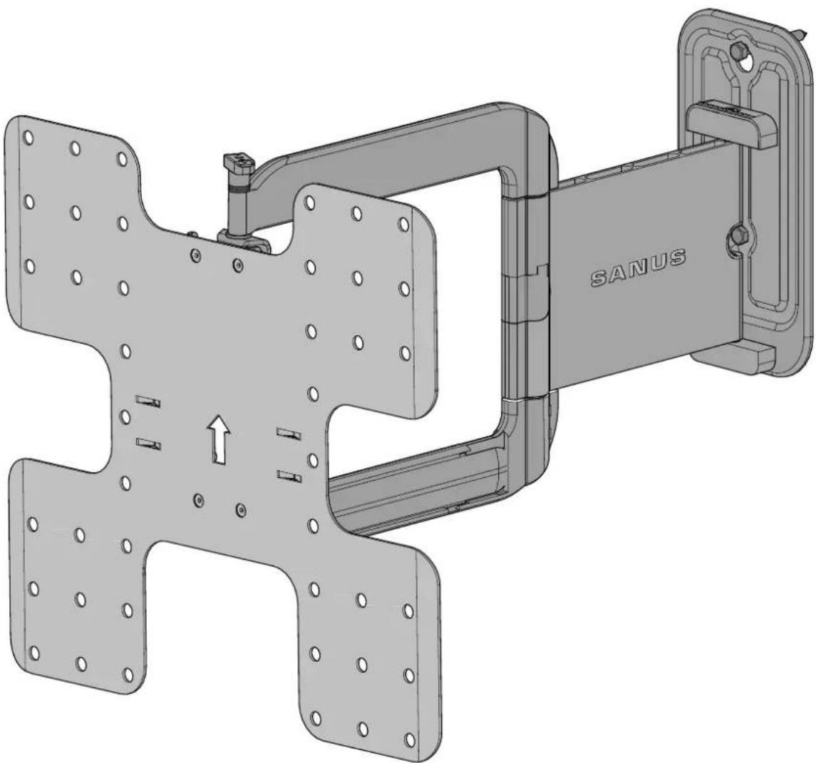
VMF322 Instruction Manual
natural_image
Technical illustration of a mechanical assembly with labeled components (SANUS), showing internal components and mounting features without any readable text or symbols.We are here to help!
Please contact Customer Service with any questions.
Customer Service
Americas: 800-359-5520 · 952-225-6013 · info@sanus.com
Europe, Middle East, and Africa: +31 40 2324700 • europe.sanus@milestone.com
Asia Pacifi c: 86 755 8996 9226 • sanus.ap@milestone.com
SANUS • 6436 City West Parkway • Eden Prairie, MN 55344 USA
©2012 Milestone AV Technologies, a Duchossois Group Company. All rights reserved. Sanus is a division of Milestone.
All other brand names or marks are used for identification purposes and are trademarks of their respective owners.
English - How to use this manual
For best results, reference both the text and illustrations.
OR Select one item or the other.
OPT This item is optional
English Text Pages 3-13
IMPORTANT SAFETY INSTRUCTIONS – SAVE THESE INSTRUCTIONS – PLEASE READ ENTIRE MANUAL PRIOR TO USE
Specifications
Weight capacity-DO NOT EXCEED: 27.2 kg (60 lb.) includes TV and any accessories
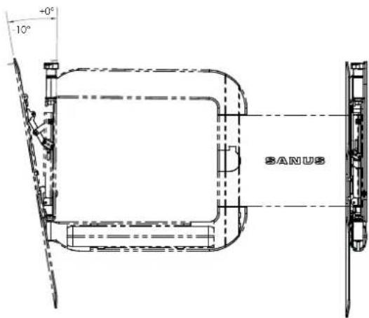
Tilt: -10°
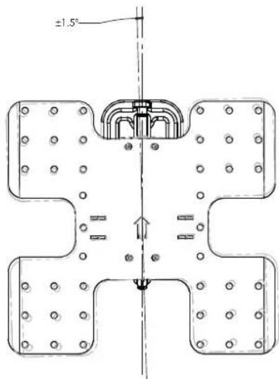
Level: ±1.5°
CAUTION: Avoid potential personal injuries and property damage!
Do not use this product for any purpose not explicitly specified by manufacturer.
The wall must be capable of supporting five times the weight of the monitor and mount combined.
This product is not designed for use in metal stud walls!
If you do not understand these instructions, or have doubts about the safety of the installation, assembly or use of this product, contact Customer Service or call a qualified contractor.
Manufacturer is not responsible for damage or injury caused by incorrect assembly or use.
Technical Specifications
in.
![[mm] 1.38 [34.9] 22.08 [560.9]](/content/2026/04/673642/images/498c04b4e0bc945ddd112cd58201eb23125f2aae83775849ef5a6a027cf23951.jpg)
![1.5 [38] VERTICAL OFFSET 15.75 [400.0] 11.81 [300.0] 7.87 [200.0] 15.75 11.81 7.87 [400.0][300.0] [200.0] 3.94 [100.0] 17.13 [435.2] Q WALL PLATE 3.78 [95.9] WALL PLATE OFFSET 22.16 [562.9]](/content/2026/04/673642/images/32fbacad4411c4172d0de18cb0b7b970ee4560d2b1decd218173f6dfb83f70c6.jpg)
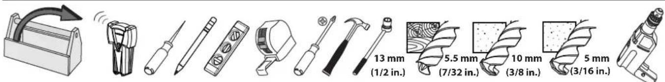
Supplied Parts and Hardware
WARNING: This product contains small items that could be a choking hazard if swallowed.
Before starting assembly, verify all parts are included and undamaged. If any parts are missing or damaged, do not return the damaged item to your dealer; contact Customer Service. Never use damaged parts!
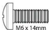
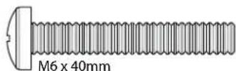
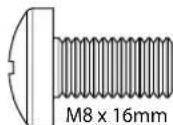
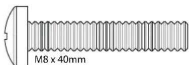
NOTE: M4, M6, or M8 describes the diameter, mm describes the length of screws that are labeled M# X ##mm. Not all hardware included will be used.
natural_image
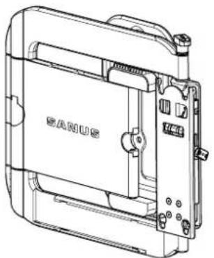
Technical line drawing of a device casing with no visible text or symbols[01] × 1
natural_image
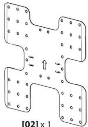
Diagram of a mechanical or electronic component with four rectangular parts and circular holes, showing internal structure and directional arrows (no text or symbols)[02] × 1
natural_image
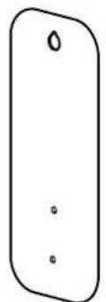
Simple line drawing of a rounded rectangular shape with three small dots inside (no text or symbols)[03] × 1
natural_image
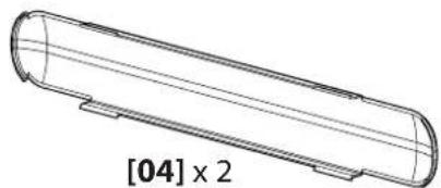
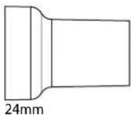
Technical line drawing of a cylindrical mechanical part with rounded ends and a cross-sectional view labeled [04] x 2 (no other text or symbols)
[05] × 2
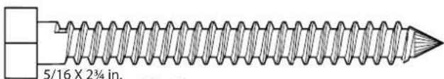
[06] × 2
M4 x 12 mm
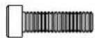
[07] x 2
M4 x 12mm
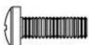
[08] x 4
[09] × 4
[10] × 4
[11] × 4
[12]×4
[13] × 4
M4 M6 / M8
[14] × 4 [15] × 4
[16] × 4
14mm
[17] × 4 [18] × 4
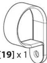
[19] × 1
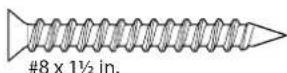
[20] × 1 [21] × 1
![[22] x 6 M3 5/32 in. [25] x 2](/content/2026/04/673642/images/2c47d44b66bd1891574ea2035d99c317aa9a27271c099d865fd525129589a903.jpg)
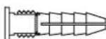
[23] × 1 [24] × 1
SANUS®
1-1 Select the hardware diameter and length
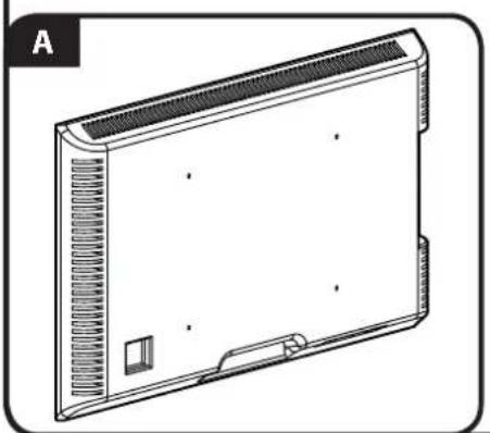
Your TV type will help you determine which hardware configuration to use. Match your type of TV to the suggested hardware configuration on the next page.
A. Installation option without spacers (TVs with flat backs)
B. Installation option using 14mm spacers (TVs with irregular backs)
C. Installation option using 24mm spacers (For TVs with irregular backs that require more length than the 14mm spacer provides.)
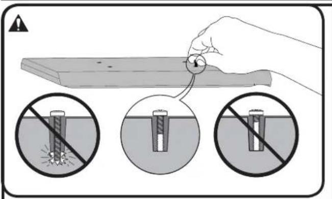
Hand thread screws into the threaded inserts on the back of your TV to determine the correct screw diameter (M4, M6, or M8).
CAUTION: Avoid potential personal injuries and property damage! Verify that there are adequate threads to secure the brackets to the monitor. If you encounter resistance, stop immediately and contact customer service. Use the shortest screw and spacer combination to accommodate your needs. Using hardware that is too long may damage your TV.
natural_image
Line drawing of a rectangular electronic device with ventilation grilles and mounting bracket (no text or symbols)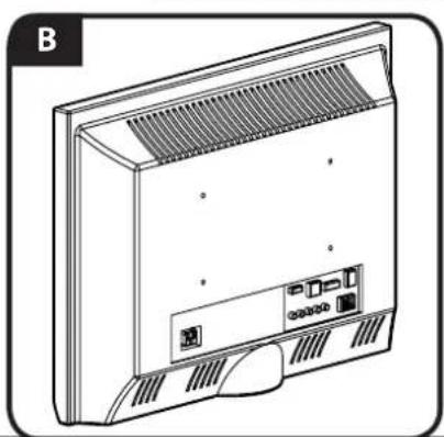
natural_image
Line drawing of a front panel with ventilation grilles and ports (no text or symbols)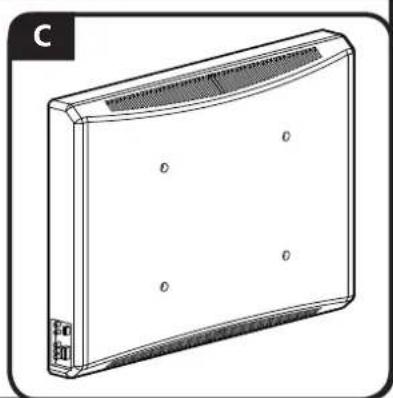
natural_image
Line drawing of a rectangular electronic device with ventilation grilles and mounting ports (no text or symbols)1-2 Attach bracket to a TV with a fl at back
![[02]](/content/2026/04/673642/images/107b51a7e027869760eba3c98e7ac252532605cc555ae059a4e4ca4186ac5e7b.jpg)
In step 1-1 if you selected the:
M4 x 12mm screw [08] use the M4 washer [14].
M6 x14mm screw [10] use the M6/M8 washer [15].
M8 x16mm diameter screw [12] use the M6/M8 washer [15].
Confir rm that the brackets are level on the back of the TV.
If you require additional space for cables, recesses, or protrusions, choose one of the following configurations.
![[02] [14, 15] [08, 10, 12]](/content/2026/04/673642/images/7537710e348c14c01b0a379bf534fd0489953085c7efa774711e228abaefbb63.jpg)
1-2 Attach bracket to a TV with an irregular back
![[17, 18] [16] [02]](/content/2026/04/673642/images/25a4716b2cbf3d0153999a1dadb5a6d6ac4c682612cad652ab93fe91de4f9979.jpg)
![2 [02] [16]](/content/2026/04/673642/images/8452d57de214e4390b3a169b5caa1196bbe287e5ce819e71f6f119578e44e729.jpg)
- Push the shoulder washer [16] through the appropriate openings of the brackets [02].
- Snap shoulder washer [16] into the spacer you selected in step 1-1.
If your TV has a curved or obstructed back, or if you need more room to accommodate cables, recesses, or protrusions, use either the 14mm, or 24mm spacer [17 or 18].
![[02] OR](/content/2026/04/673642/images/bc35151b04b15fbd87909ff5f91331a4d40f19ebb7cd35aa609ca6566a43fc6d.jpg)
In step 1-1 if you selected the:
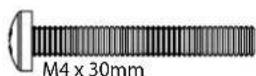
M4 x 30mm screw [09] use the M4 washer [14] and spacer [17].
M6 x 40mm screw [11], use the M6/M8 washer [15] and spacer [18].
M8 x 40mm screw [13], use the M6/M8 washer [15] and spacer [18].
Confir rm that the brackets are level on the back of the TV. Standard confi gurations are shown. For special applications, or if you are uncertain about your hardware selection, contact Customer Service.
![M4 [17] [16] [14] [02] [09]](/content/2026/04/673642/images/5642a2142d7511b7846fc0b709948645dadadc2270fd5ef1d2ea2d64588d5d66.jpg)

![M6/M8 [18] [16] [15] [02] [11, 13]](/content/2026/04/673642/images/c7f155d9d02b2e7284ecd1112bb29cecf043b1b5dd0684fdad1c83891592523c.jpg)
2 Mount the Wall Plate
Wood stud
2-1 Locate stud
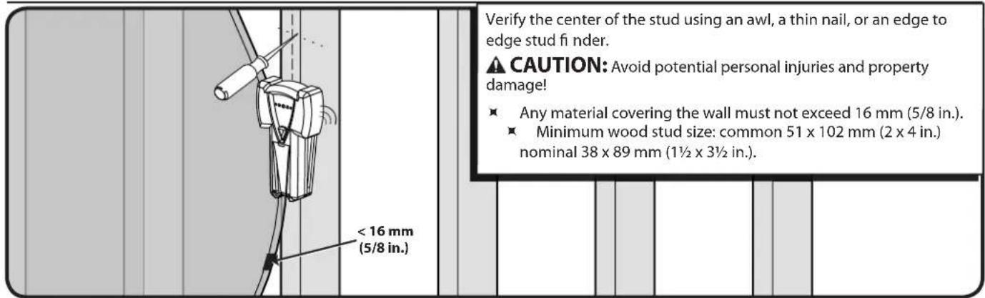
2-2 Mark the wall
![[03] OPT For assistance in determining wall plate location, see Height Finder at sanus.com. Level the wall plate template [03] and mark the hole locations. The third hole is for the cable management clamp [19] and is optional. OPT](/content/2026/04/673642/images/2954b6f44212c7907d7f5f2bca0e6c50752625ced3fd1ec4b2027a4cddfc6836.jpg)
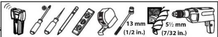
2-3 Drill pilot holes
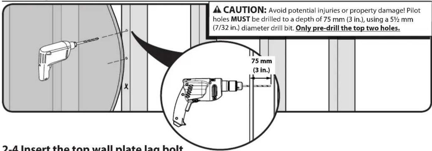
2-4 Insert the top wall plate lag bolt
![[06] Insert only the top plate lag bolt [06] at this time. CAUTION: Improper use could reduce the holding power of the lag bolt. To avoid potential injuries or property damage: DO NOT over-tighten the lag bolt [06].](/content/2026/04/673642/images/2ae48103f2b2caa91cde38a97b1a81274bf160cf2237195f8e150503598dd8a1.jpg)
2-5 Hang the wall plate onto the lag bolt
![Hang the wall plate [01] over the top lag bolt [06]. [01] BANUS [06]](/content/2026/04/673642/images/cc35520499d6b521e0c8fac69ac6ff1b2272f75054dc0ed5d1cec9a5e2c0b705.jpg)
2-6 Tighten wall plate lag bolts
![[01] [06] X CAUTION: Improper use could reduce the holding power of the lag bolt. To avoid potential injuries or property damage: ■ DO NOT over-tighten the lag bolts [06]. ■ Tighten the lag bolts [06] only until they are pulled firmly against the wall plate [01].](/content/2026/04/673642/images/62ec4878b244c987cafae2d927d56ddd53f0367be9fc2cb2b0d8365178aa8cda.jpg)
2-7 Attach the cable management clamp
![[01] [20] [19] Secure the cable clamp [19] to the wall using screw [20]](/content/2026/04/673642/images/0e3f6b50a67910d31ddfeb864a6a35efab4bdf998094fb0439229752e48b33ff.jpg)
2 Mount the Wall Plate Solid concrete or concrete block
2-1 Mark the wall
![For assistance in determining wall plate location, see Height Finder at sanus.com. Level the wall plate template [03] and mark the hole locations. The third hole is for the cable management clamp [19] and is optional. CAUTION: Avoid potential injuries or property damage! ■ Mount the wall plate [01] directly onto the concrete surface. ■ Minimum solid concrete thickness: 203mm (8 in.). ■ Minimum concrete block size: 203 x 203 x 406 mm (8x x 16 in.). OPT](/content/2026/04/673642/images/d12e0941908eaa3794c251cdd306cd2bca138260883a69214d525b8e10a2a145.jpg)
2-2 Drill pilot holes
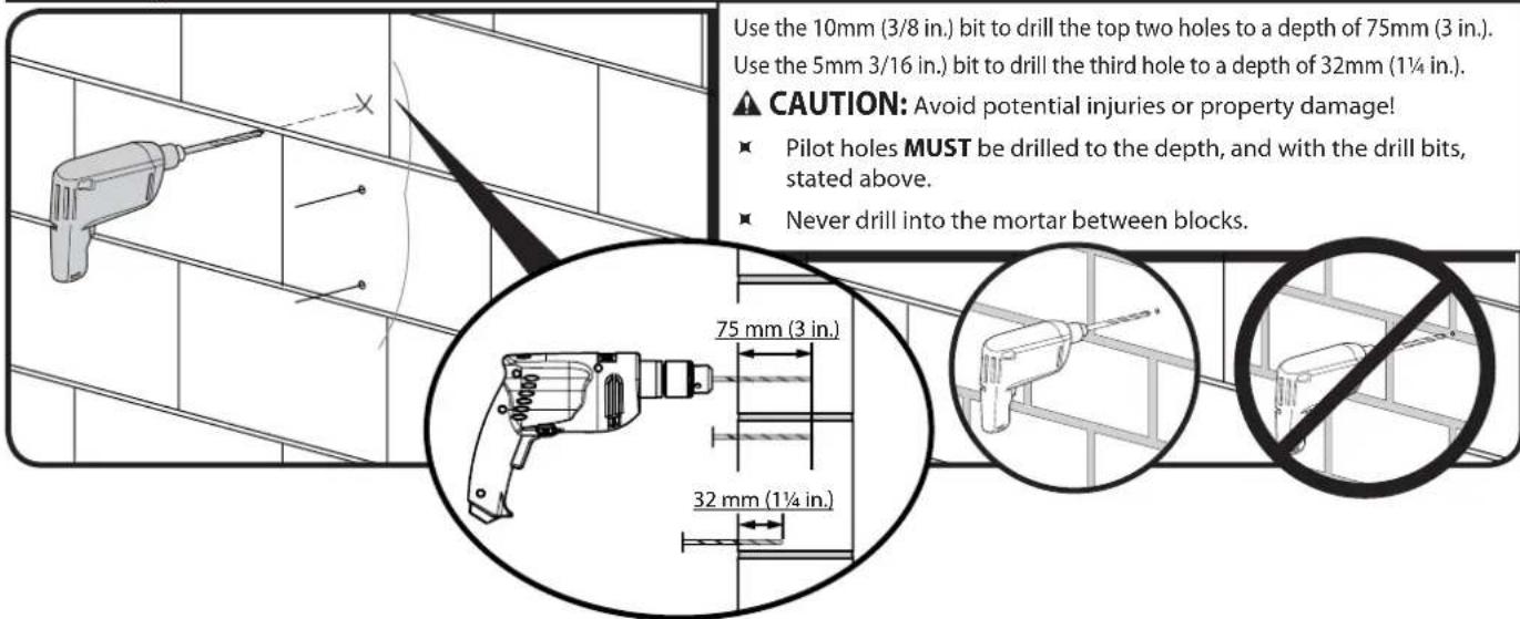
2-3 Insert anchors
![[05] [05] [21] Insert lag bolt anchors [05] into the top two holes. Insert anchor [21] into the last hole. ⚠️ CAUTION: Improper use could reduce the holding power of the lag bolt. To avoid potential injuries or property damage: Be sure the anchors [05, 21] are seated flush with the concrete surface.](/content/2026/04/673642/images/bc1025be90c2cd8a04ac2baf9088ef6fa71bfdf076948dc9bfc9ba64d2040a0e.jpg)
2-4 Insert lag bolts
![Insert only the top plate lag bolt [06] at this time. ⚠️ CAUTION: Improper use could reduce the holding power of the lag bolt. To avoid potential injuries or property damage: DO NOT over-tighten the lag bolt [06]. [05] [06] [05] [21]](/content/2026/04/673642/images/75d7dba18cbf609350703c6447ea1a07e3242b5c406c599dacd07a8bb74c6dc1.jpg)
2-5 Hang the wall plate onto the lag bolt
![[01] [05] [06] Hang the wall plate [01] over the top lag bolt [06]. [05] [21]](/content/2026/04/673642/images/6d2461fb4604914da3e3f4d75e7c575af06a5d38e1f224b11686852072a19733.jpg)
2-6 Tighten lag bolts
![[01] [06] [06] [21] Insert lag bolts [06] through the wall plate [01] and into the anchors [05]. ▲ CAUTION: Improper use could reduce the holding power of the lag bolt. To avoid potential injuries or property damage: ■ Tighten the lag bolts [06] only until they are pulled firmly against the wall plate [01]. ■ DO NOT over-tighten the lag bolts [06].](/content/2026/04/673642/images/6c07f54110c82a4cb7df1aba3de0ac9feb0e2d2942eeb38fc438a55cd17039ae.jpg)
2-7 Attach the cable management clamp OPT
![Secure the cable clamp [19] to the wall using screw [20]. [01] [19] [20]](/content/2026/04/673642/images/f99e98b27d78e9b704a48ca5931c01fffad023e4e26f037e747a7d33a67f9fa5.jpg)
![HEAVY! You will need assistance with this step. Move the TV interface buttons (B) over and into the keyhole slots (S) on the arm [01]. Secure with the safety screws [07] using allen key [23]. [S] [S] [02] [B] [SANUS] [01] [01] [02] [B] [07] [23] 4 Adjustments](/content/2026/04/673642/images/d3885c438075727cb2d27b664f90bded61077ad34cb2e204ac3aa53ac23a8d9b.jpg)
4 Adjustments
![1. Adjust tilt tension tension using either the finger tip tilt function OR by turning the tilt adjustment knob by by hand or with the M3 allen key [23]. 2. Adjust level using the 5/32 in, allen key [24].](/content/2026/04/673642/images/74ca43423879c65d8362813e6530f8ea82801fb3f6d5ccf408670a9eb16d0704.jpg)
![1 SANUS [22] [22]](/content/2026/04/673642/images/6c1fe3e6ddf8c4c94d32ae905c63d6f6083efc048d308ba25be604c2497c54bb.jpg)
- Thread cable ties [22] through the slots in the arm [01]. Route cables alongside the arm [01] and secure with cable ties [22].
- Attach cable covers [04] to the arm [01].
- Route cables through the cable clamp [19].
![SANUS [04] [22] [04]](/content/2026/04/673642/images/32b4bc8be947f26dfa47ee6374b5e20b44f43b0f49bc4d51e51a2fe9aec8d067.jpg)
![3 SANS [19]](/content/2026/04/673642/images/f0ea52770f071d35a1b3a5a1187cf96175f9d6ad3e6da0e40b820b3a230b69e1.jpg)

![[01] [25]](/content/2026/04/673642/images/eb74b4f48de78131659f17470419732dcb431cf00dc6763604662fafacfe169c.jpg)
To prevent the arm [01] from touching the wall when the TV is in the flush position, place the felt pads [25] on the arm [01].
![WALL [25] [01] TV](/content/2026/04/673642/images/00c39031c6c00af51b95d3286590092e9a37f5ea320fb5dddbc19793d1131ea7.jpg)
Français
CONSIGNES DE SÉCURITÉ IMPORTANTES – CONSERVEZ CES INSTRUCTIONS – VEUILLEZ LIRE ATTENTIVEMENT LE MANUEL AVANT D'UTILISER CE PRODUIT
Milestone AV Technologies and its affiliated corporations and subsidiaries (collectively, "Milestone"), intend to make this manual accurate and complete. However, Milestone makes no claim that the information contained herein covers all details, conditions, or variations. Nor does it provide for every possible contingency in connection with the installation or use of this product. The information contained in this document is subject to change without notice or obligation of any kind. Milestone makes no representation of warranty, expressed or implied, regarding the information contained herein. Milestone assumes no responsibility for accuracy, completeness or sufficiency of the information contained in this document.