
BIWLF128 - Wall mount SANUS - Free user manual and instructions
Find the device manual for free BIWLF128 SANUS in PDF.

| Product Type | Articulating flush-mount wall mount |
| Brand | SANUS |
| Model | BIWLF128 |
| Maximum Load Capacity | 61.2 kg (135 lb) |
| Main Material | Steel |
| Tilt adjustable | Yes, with tension knob |
| Cable management | Integrated along the arm |
| Minimum wall cavity depth | 99 mm (3.9 in) |
| Maximum drywall thickness | 1.5 cm (5/8 in) |
| Minimum wood stud size | 3.8 x 8.9 cm (1½ x 3½ in) (nominal 5.1 x 10.2 cm) |
| Horizontal fastener spacing | 40.6 cm (16 in) minimum |
| Installation type | On wood studs only |
| Usage | Indoor |
| Level adjustment | Yes, by leveling screw |
| Security | Locking screw for TV security |
| Required tools | Measuring tape, pencil, level, screwdriver, drill, stud finder, awl, wood drill bit |
| Care and cleaning | Wipe with a dry cloth; do not use abrasive products |
| Spare parts | Screws, spacers, anchors, covers included; contact customer service for replacement |
| Phone support | +1 (800)-359-5520 (United States) |
| Help website | SANUS.com/3153, MountFinder.Sanus.com |
Frequently Asked Questions - BIWLF128 SANUS
User questions about BIWLF128 SANUS
0 question about this device. Answer the ones you know or ask your own.
Ask a new question about this device
Download the instructions for your Wall mount in PDF format for free! Find your manual BIWLF128 - SANUS and take your electronic device back in hand. On this page are published all the documents necessary for the use of your device. BIWLF128 by SANUS.
USER MANUAL BIWLF128 SANUS
natural_image
Technical line drawing of a mechanical assembly with mounting brackets and structural supports (no text or symbols)WE'RE HERE TO HELP
natural_image
Person using a play button on a black surface, no visible text or symbolsWant to watch a video that shows how easy this is?
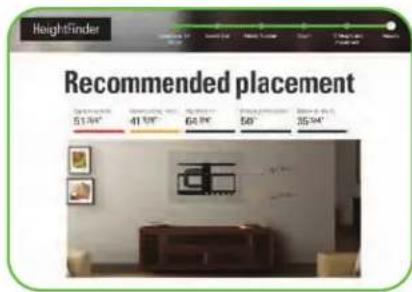
Get it right the first time. HeightFinder™ shows you where to drill.

natural_image
Group of professionals in a modern office environment, smiling while working at workstations (no visible text or signage)Our live install experts are standing by to help.

Watch it now at: SANUS.com/3153

Use it now: SANUS.com/2566

Call us at: +1 (800) 359-5520

IMPORTANT SAFETY INSTRUCTIONS
- PLEASE READ MANUAL PRIOR TO USE - SAVE THESE INSTRUCTIONS
WARNING: Avoid potential personal injuries and property damage!
- DO NOT INSTALL THIS MOUNT IN A FIREWALL (The wall between a garage and a living space, or the wall between two condominiums or occupancies sharing a wall). Contact your local building inspector before cutting a hole in the drywall if unsure.
- This product is designed ONLY to be installed into wood stud walls—DO NOT INSTALL INTO DRYWALL ALONE
- Do not use this product near water; such as a bath tub, wash bowl, kitchen sink, laundry tub, swimming pool, or in a wet basement.
- Equipment shall be installed in accordance with ANSI/NFPA 70, National Electrical Code (NEC), NFPA 72, CAN-ULC-S540, Canadian Electrical Code, and/or other applicable sections of ANSI/IEEE C2 & National Electrical Safety Code (NESC). Equipment intended for installation in information technology equipment (computer) rooms should be installed in accordance with NFPA 75, Standard for the Fire Protection of Information Technology Equipment.
● Installation shall be completed by a professional electrical contractor or low voltage technician. - Do not use this product for any purpose not explicitly specified by manufacturer
● Manufacturer is not responsible for damage or injury caused by incorrect assembly or use
Please read through these instructions completely to be sure you're comfortable with this easy install process.
Check your TV owner's manual to see if there are any special requirements for mounting your TV.
If you do not understand these instructions or have doubts about the safety of the installation, assembly or use of this product, contact Customer Service: +1 (800)-359-5520
TV Weight Limit
(including accessories)
DO NOT EXCEED
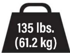
If your TV (plus accessories) weighs MORE, this mount is NOT compatible.
Visit SANUS.com or call customer service to find a compatible mount.
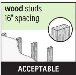
Wall Construction
ONLY install on wood stud wall.
CAUTION:
DO NOT install in drywall alone
Drywall alone will NOT hold the weight of your TV.

Tools Needed
Measure
Finder
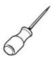
AwlPencil Level TapeStud

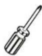
ScrewdriverTape
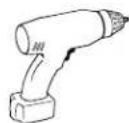
Drill BitElectric Drill
Dimensions
TV INTERFACE
![3.9 [100.0] 23.6 [600.0] 15.7 [400.0] 3.9 [100.0]](/content/2026/04/673622/images/b4694737754686964fbf8b9dfe333177f51d302e11758bff868735eca6ed7ed4.jpg)
3-D
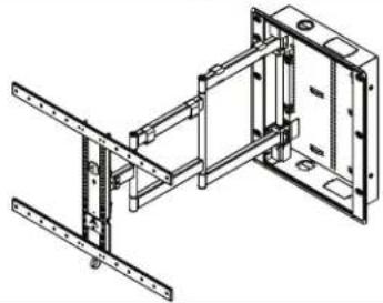
natural_image
Technical line drawing of a structural frame assembly (no text or symbols)WALL PLATE
![16.0 [406.4] 7.8 [196.9] 2.5 [63.5] 15.5 [393.7] 18.1 [460.8] 20.8 [529.0]](/content/2026/04/673622/images/c9b2aed2b3edc0fcaa3ab69b91279ed6fe1b45bce8f664332166418aeb8aa3c4.jpg)
TOP VIEW - EXTENDED
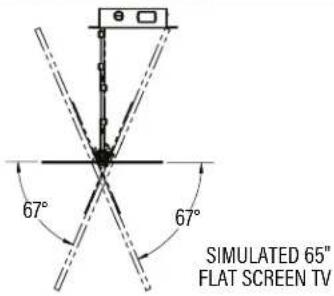
SIDE VIEW - EXTENDED
![28.0 [710.6] 4° UP 15° DOWN](/content/2026/04/673622/images/7e89178ee2d531e80f91382ab348233ee2b4c4696ea6256017f650d021635da4.jpg)
FULLY ASSEMBLED MOUNT
![24.9 [632.6]](/content/2026/04/673622/images/55e6afa11af65df00f38a66cbdd9e8325f4fc19d32ceb9f2e561d7761f2aef4a.jpg)
TOP VIEW - RETRACTED
![14.0 [355.6]](/content/2026/04/673622/images/b4b721646e9758c9a642a271e10f8588ee7cb238cdf19ac9af81b675be569fd7.jpg)
SIDE VIEW RETRACTED
![0.5 [13.5] 3.9 [98.0] 19.3 [490.9]](/content/2026/04/673622/images/733fd946c9271965886d3619674571b2899952227a29a697f3c9ebe96652d600.jpg)
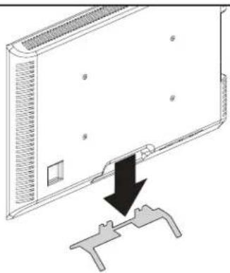
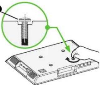
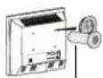
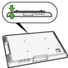
BEFORE YOU BEGIN
Remove the stand
from your TV — if attached.
natural_image
Diagram showing a device with a black arrow pointing to a mechanical component (no text or symbols present)Install any accessories
you may have purchased, if they require TV removal prior to assembly. The TV is removable for future accessory purchases.
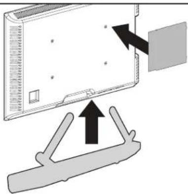
natural_image
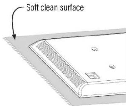
Diagram showing a device with an arrow pointing to a component, and a separate bracket with an upward arrow (no text or symbols present)Protect the face
of your TV when laying it down for installation.
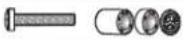
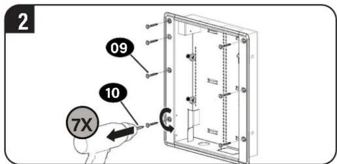
Supplied Parts and Hardware
WARNING: This product contains small items that could be a choking hazard if swallowed. Before starting assembly, verify all parts are included and undamaged. If any parts are missing or damaged, do not return the damaged item to your dealer; contact Customer Service. Never use damaged parts!

NOTE: Not all hardware included will be used.
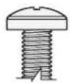
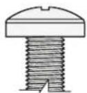
![STEP 1 01 TV Screws (qty. 4 each) [Only one size fits your TV] M6 M6 x 25mmM6 x 12mm M8 M8 x 16mm M8 x 30mm M8 x 20mm M8 x 40mm M8 x 50mm 02 Washers (qty. 4) M6/M8 03 Spacers (qty. 4 each) 2.5mm 5mm 04 TV Bracket Horizontal (qty. 2) 05 TV Bracket Vertical (qty. 1) M5 x 11 mm TV Interface Screw 06 (qty. 4)](/content/2026/04/673622/images/62304683c8f4fb24d013e29420b9b86a44cb008ab19023d7a4fcc2d0c159ec66.jpg)
STEP 1 Attach TV Brackets to TV
Only one screw size fits your TV.
M6
O
M8
[NO TEXT]
01

NOTE: If your TV
included inset spacers or adapters, use them UNDER the mount hardware.
1
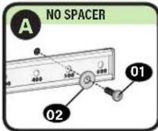
1-2 Select TV Screw Length and Spacers 1-1 Select TV Screw Diameter

NO SPACER SPACER NEEDED
- Flat Back TV
[TV brackets lay flat on your TV]
| Use short TV screws 01, Spacers 03 not needed. |
natural_image
Diagram of a device with a green arrow pointing to a component, showing no text or symbols.
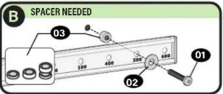
- Flat Back TV with extra space needed [for deep inset holes or cable interference]
- Rounded or Irregular Back TV [TV brackets NOT resting flat on your TV]
Use long TV screws 01 and spacers 03 to create extra space between the TV and TV bracket.
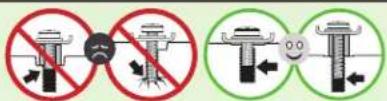
CAUTION: Verify adequate thread engagement with your screw 01, washer 02, spacer 03 combination AND TV bracket 04.
— Too short will not hold your TV. — Too long will damage your TV.
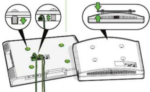
1-3 Attach TV Brackets to Your TV
1
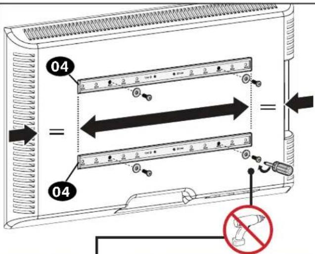
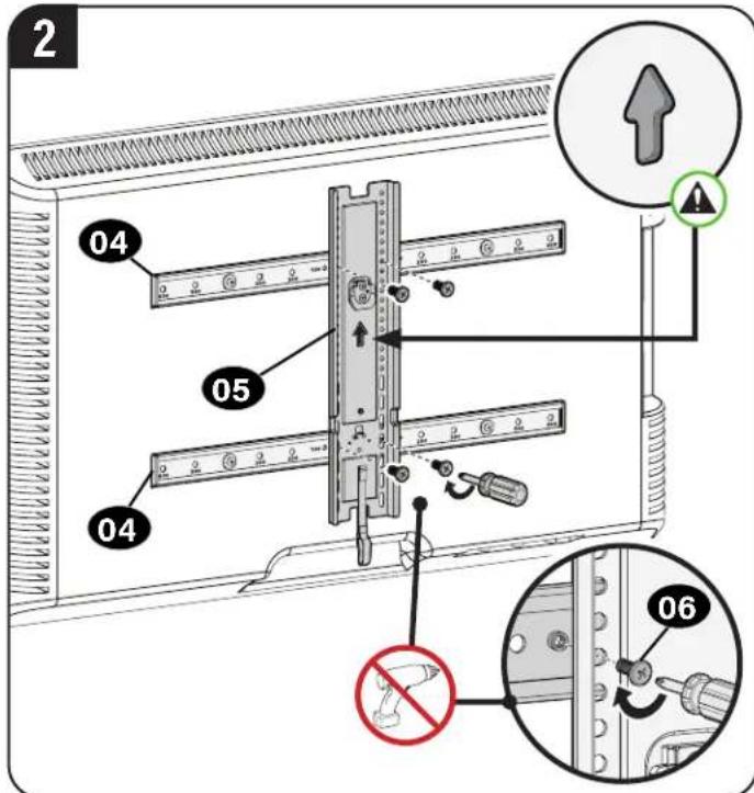
CAUTION: Avoid potential personal injuries and property damage! DO NOT use power tools for this step. Tighten the screws 01 and 06 only enough to secure the TV brackets to the TV.
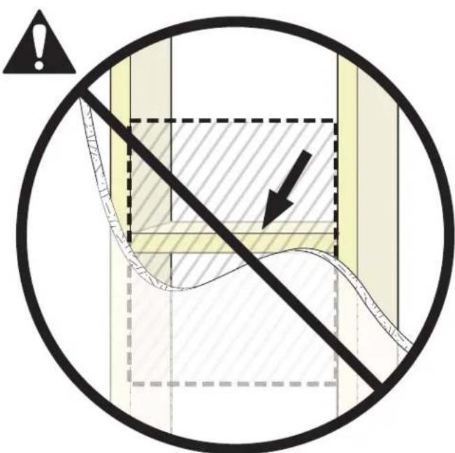
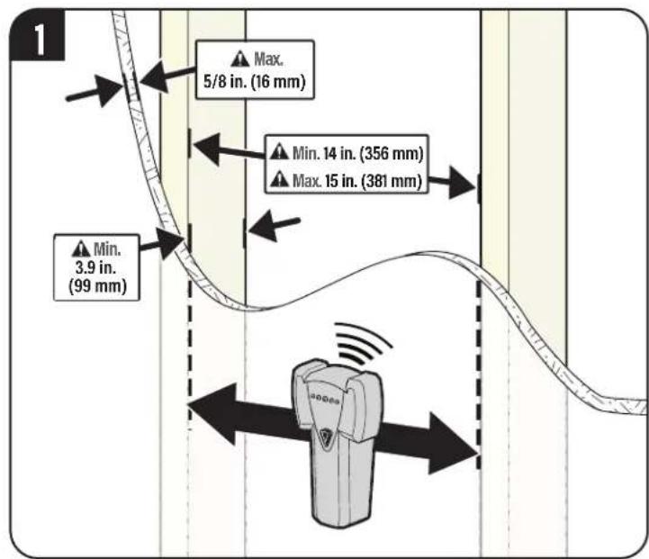
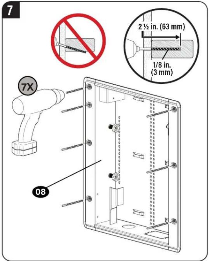
AUTION: Avoid potential personal injury or property damage!
• Drywall covering the wall must not exceed 5/8 in. (16 mm)
● Minimum wood stud size: nominal 2 x 4 in. (51 x 102 mm) actual 1½ x 3½ in. (38 x 89 mm)
- Spacing between studs: 14 in. to 15 in. (356 mm to 381 mm)
• Minimum depth into wall cavity: 3.9 in (99 mm)
- Verify there are no obstructions in the wall cavity, behind the area you intend to install.
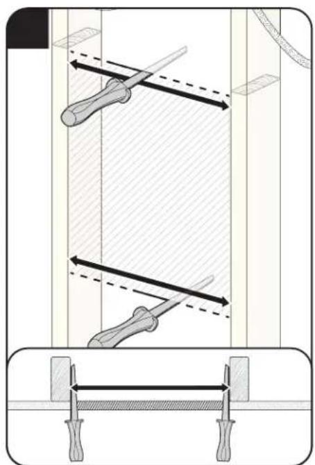
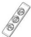
natural_image
Technical diagram showing a mechanical assembly with two tools and directional arrows, no text or symbols present.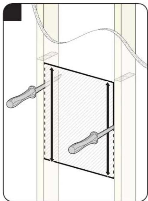
natural_image
Diagram showing two screwdrivers inside a rectangular frame with directional arrows, no text or symbols present.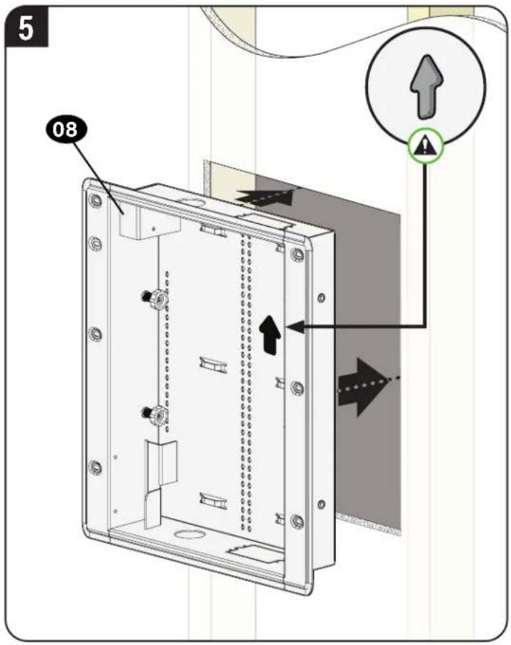
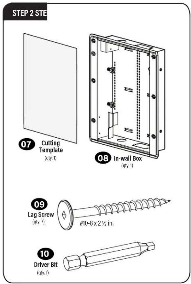
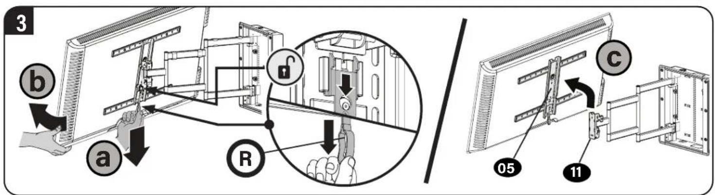
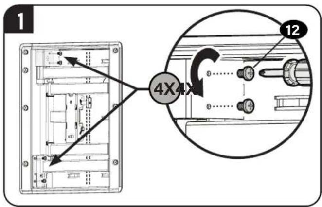
STEP 3 Hang your TV onto The In-wall Box
3-1 Attach Arm Assembly to the In-wall Box
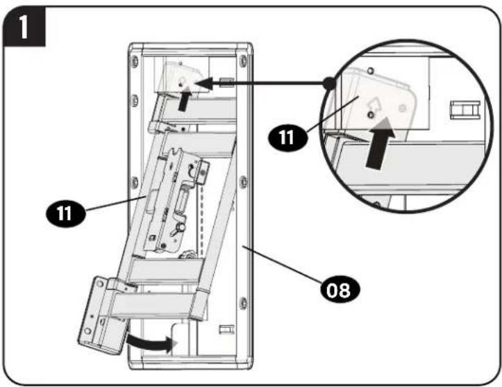
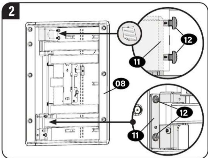

NOTE: The top two screws 12 will not seat fully - tighten until snug.
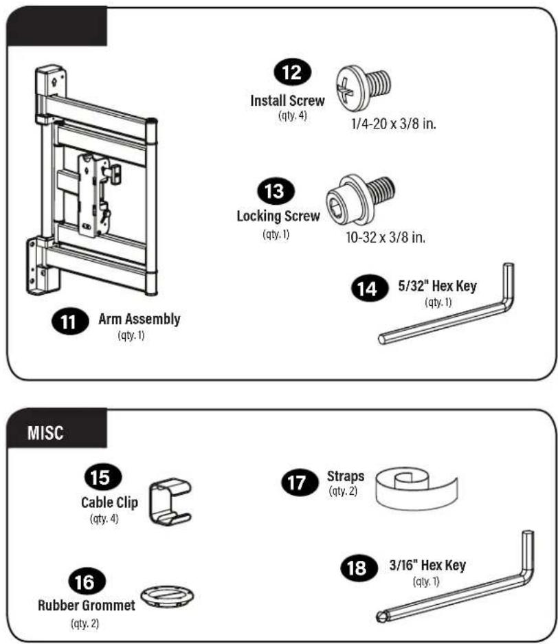
3-2 Attach TV to Arm Assembly

HEAVY! You may need assistance with this step.
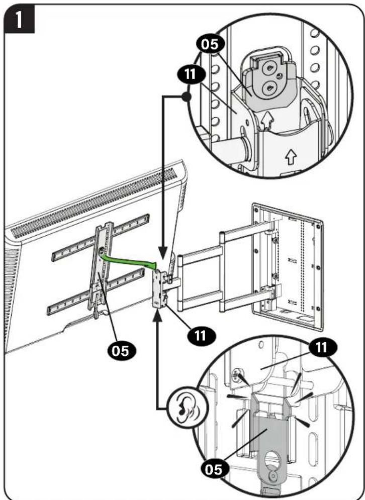
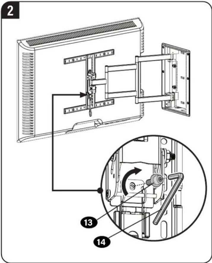

CAUTION: Avoid potential injuries or property damage!
Locking screw 13 MUST be installed to secure the TV mount and the arm assembly.
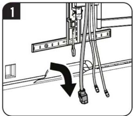
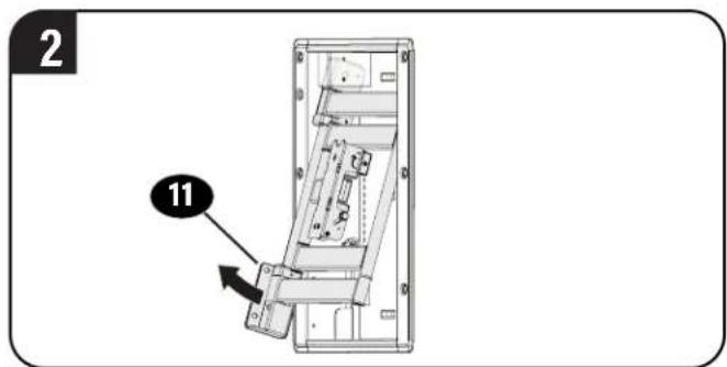
Manage Cables
1
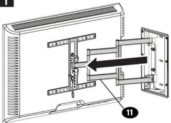
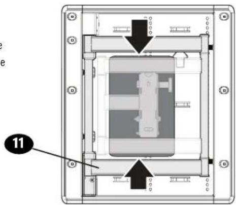
IMPORTANT: Fully extend arm assembly 11 to ensure enough slack in cables. Route your cables through the arm assembly
11 and secure with clips 15
IMPORTANT: Be sure cables are not in a position to be pinched when mount is in motion.
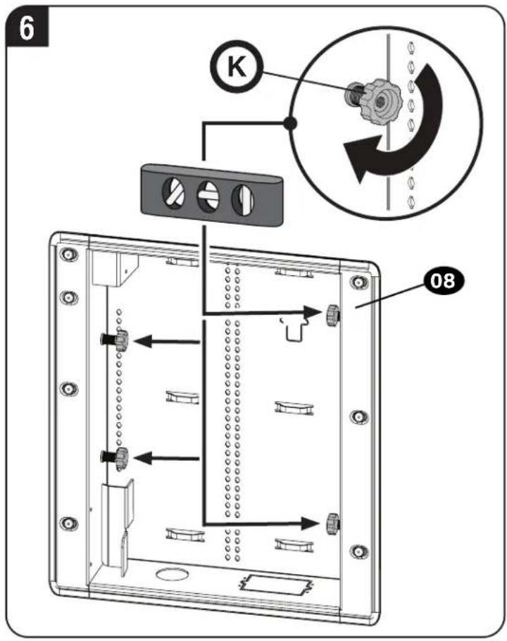
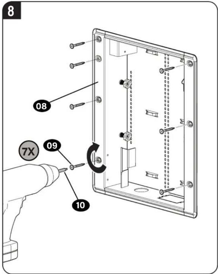
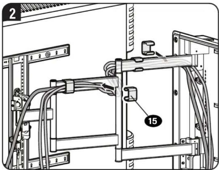
Install Components
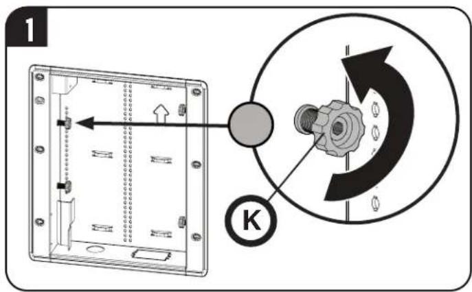
Junction Box (Not Included)
WARNING: Electric Shock Hazard! Avoid potential serious injuries or death. Consult a qualified electrician for proper installation.
NOTE: Knock-outs K are provided for the installation of a UL Listed electrical junction box (not included) and UL Listed receptacle (not included).
CAUTION: If installing a junction box, follow all instructions included with the UL Listed electrical junction box and UL Listed receptacle.
natural_image
Diagram of a device interior showing internal components and wiring, with no visible text or symbols.Secure components with straps 17 and hole plugs 16.
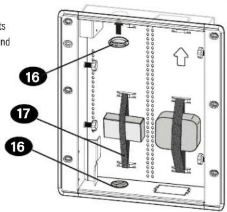
NOTE: Install components so they don't interfere with the arms 11 when in the home position.
natural_image
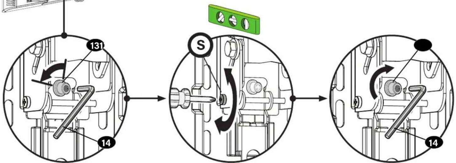
Technical diagram of a mechanical assembly with labeled components and directional arrows (no readable text or symbols)TV Adjustments

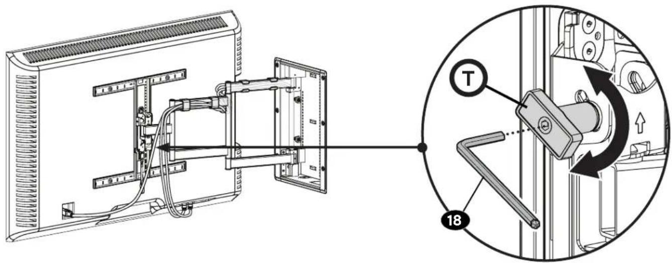
TILT ADJUSTMENT
Your TV should adjust easily when moved, then stay in place.
If your TV is too loose or too tight, adjust the side tension knob Ⓣ

NOTE: Once your TV is in place, tighten the tension knob T to prevent unwanted movement.

NOTE: Additional tension can be applied using hex key 18.

LEVEL ADJUSTMENT
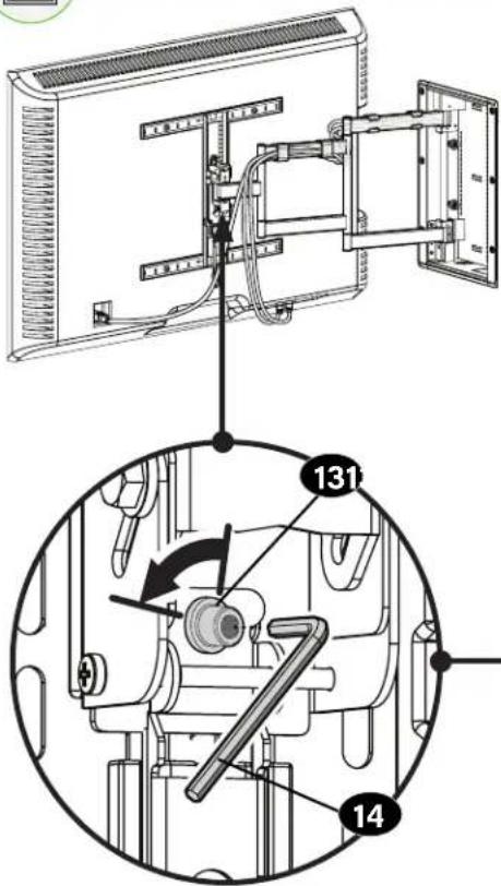

CAUTION:
Screw 13 MUST be loosened before turning
screw S

CAUTION: Avoid potential personal injury or property damage!
Always make sure your securement screw 13 is tightened, so the TV is securely fastened to the arm assembly.
flowchart
graph TD
    A["Start"] --> B["Component 131"]
    B --> C["Component 14"]
    C --> D["Component S"]
    D --> E["Component 14"]
    E --> F["End"]

REMOVING THE TV

HEAVY! You may need assistance with this step.
natural_image
Diagram showing a mechanical assembly with wires and a black arrow indicating direction (no text or symbols)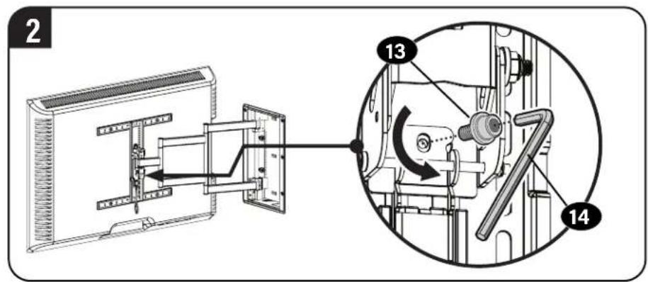

REMOVING THE ARM REMOVING THE BOX

NOUS SOMMES LÀ POUR VOUS AIDER
Thank you for choosing Sanus! Please take a moment to let us know how we did:
Legrand AV Inc.
6436 City West Parkway
Eden Prairie, MN 55344 USA
+1 (800) 359-5520
SANUS.com
Legrand AV Inc. and its affiliated corporations and subsidiaries (collectively, "Legrand"), intend to make this manual accurate and complete. However, Legrand makes no claim that the information contained herein covers all details, conditions, or variations. Nor does it provide for every possible contingency in connection with the installation or use of this product. The information contained in this document is subject to change without notice or obligation of any kind. Legrand makes no representation of warranty, expressed or implied, regarding the information contained herein. Legrand assumes no responsibility for accuracy, completeness or sufficiency of the information contained in this document.
©2023 Legrand AV Inc. All rights reserved. SANUS is a brand of Legrand. SANUS, HeightFinder and the SANUS logo are trademarks of Legrand.