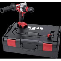
DD 2G 18.0-EC - Drill Flex - Free user manual and instructions
Find the device manual for free DD 2G 18.0-EC Flex in PDF.


| Product Type | Cordless Drill/Driver |
| Brand | Flex |
| Model | DD 2G 18.0-EC |
| Rated Voltage | 18 V |
| Battery Type | Lithium-ion, AP 18.0/2.5 Ah or AP 18.0/5.0 Ah |
| No-load Speed | Position 1: 0-600 min-1; Position 2: 0-2300 min-1 |
| Maximum Torque (soft/hard material) | 56 Nm / 90 Nm |
| Torque Settings Positions | 20 |
| Chuck Capacity | 1.5 to 13 mm |
| Max. Drilling Diameter (wood/steel) | 60 mm / 13 mm |
| Weight (without battery) | 1.5 kg |
| Sound Pressure Level (LpA) | 78 dB(A) |
| Sound Power Level (LWA) | 89 dB(A) |
| Vibrations (metal drilling) | < 2.5 m/s2 |
| Power Supply | 18 V lithium-ion battery |
| Main Functions | Drilling, screwdriving with torque adjustment, 2 speeds, forward/reverse, motor brake |
| Maintenance and Cleaning | Clean ventilation slots regularly with dry compressed air; do not use water or liquid products |
| Safety | Mandatory wearing of safety goggles; do not expose to rain; use original batteries |
| Spare Parts and Repairability | Exploded views and parts lists at www.flex-tools.com; repairs by authorized service center |
| General Information | Professional use in industry and trade; delivered without battery and charger |
Frequently Asked Questions - DD 2G 18.0-EC Flex
User questions about DD 2G 18.0-EC Flex
0 question about this device. Answer the ones you know or ask your own.
Ask a new question about this device
Download the instructions for your Drill in PDF format for free! Find your manual DD 2G 18.0-EC - Flex and take your electronic device back in hand. On this page are published all the documents necessary for the use of your device. DD 2G 18.0-EC by Flex.
USER MANUAL DD 2G 18.0-EC Flex
natural_image
Illustration of multiple electric drillers with exploded view, no text or symbols presentnatural_image
Mechanical assembly diagrams showing two views of a tool with fasteners and screws (no text or labels)i HINWEIS
Demontieren
Demontieren
natural_image
Close-up of a power drill with caliper and adjustment knobs (no visible text or symbols)
Drehmomentvorwahl

VORSICHT!
natural_image
Close-up of a drill bit with visible teeth and screw head (no text or symbols)1–23: Schrauben

Bohren

HINWEIS
natural_image
Close-up of a power drill bit with visible teeth and caliper (no text or symbols)natural_image
Close-up of a drill bit with a circular head indicator and directional arrows (no text or symbols on the tool itself)Gerät ausschalten:
natural_image
Illustration of a drill bit being inserted into a motor, showing the shaft and gear (no text or symbols)natural_image
Illustration of two hands using a drill press to lift a drill, showing mechanical components and tool path (no text or symbols)- Gerät einschalten.
Nach Arbeitsende:
- AP 10.8 (2,5 Ah),
- AP 18.0 (2,5 Ah),
- AP 10.8 (5,0 Ah),
- AP 18.0 (5,0 Ah).
Eckhard Rühle Manager Research & Development (R & D)
Klaus Peter Weinper Head of Quality Department (QD)
18.12.2017
Symbols used in this manual ..... 17
Symbols on the power tool 17
Important safety information ..... 17
Noise and vibration 19
Technical data 20
Overview 21
Instructions for use 22
Maintenance and care 28
Transport 29
C ∈ conformity 29
Disposal information 29
Exemption from liability 29
Symbols used in this manual

WARNING!
Denotes impending danger. Non-observance of this warning may result in death or extremely severe injuries.

CAUTION!
Denotes a potentially dangerous situation. Non-observance of this warning may result in injury or damage to property.

NOTE
Denotes application tips and important information.
Symbols on the power tool

Before switching on the power tool for the first time, read the operating manual.

Wear protective goggles.

Short-circuit-proof safety transformer.
Protect the battery against heat, including prolonged sunshine, and fire. Explosion hazard!.

Do not throw the battery into a fire. Explosion hazard!
The tool is only suitable for use indoors. Do not expose the tool to rain. Store power tools and batteries in dry rooms.
Disposal information (see page 29).
Important safety information

WARNING!
Read all safety warnings, instructions, illustrations and specifications provided with this power tool. Failure to follow all instructions listed below may result in electric shock, fire and/or serious injury. Save all warnings and instructions for future reference.
Before using the power tool, please read the following and act accordingly:
– these operating instructions,
- the "General safety instructions" on the handling of power tools in the enclosed booklet (leaflet no.: 315.915),
– the currently valid site rules and the regulations for the prevention of accidents.
This power tool is state of the art and has been constructed in accordance with the acknowledged safety regulations.
Nevertheless, when in use, the power tool may be a danger to life and limb of the user or a third party, or the power tool or other property may be damaged.
The power tool may be operated only if it is
- for its intended use,
- in perfect working order.
Faults which compromise safety must be repaired immediately.
Intended use
The DD 2G 18.0-EC cordless drill driver is intended
– for commercial use in industry and trade,
– for inserting and releasing screws,
– for drilling in wood, metal, ceramic and plastic.
The PD 2G 18.0-EC cordless percussion drill is intended
– for commercial use in industry and trade,
– for inserting and releasing screws,
– for drilling in wood, metal, ceramic and plastic,
– for impact drilling in brick, masonry and stone.
The IW 1/2" 18.0-EC / ID 1/4" 18.0-EC cordless impact driver is intended
– for commercial use in industry and trade,
– for tightening and releasing nuts and screws in the specified dimensions.
Safety instructions for drills and drivers
■ Hold the power tool by the insulated gripping surfaces when performing an operation where the cutting accessory or the screw may contact hidden wiring or its own power cord.
The screw contacting a “live” wire may make exposed metal parts of the power tool “live” and cause an electric shock.
■ Use auxiliary handles if these are supplied with the power tool. The loss of control may result in injuries.
■ Use suitable detectors to detect concealed power supply cables or consult your local supply company. Contact with electric cables may result in a fire and/or electric shock. A damaged gas pipe may cause an explosion. Cutting into a water pipe will cause damage to property.
■ Switch off the power tool immediately when the cutting accessory jams. Be prepared for high reaction torques which cause kickback. The cutting accessory jams when:
– the power tool is overloaded or
- it snags in the workpiece to be machined.
■ Maintain a firm grip on the power tool. High reaction torques can occur briefly when screws are tightened and released.
■ Secure the workpiece. A workpiece is held more securely in a clamping device or vice than by hand.
■ Wait until the power tool has come to a stop before putting it down. The cutting accessory may snag, causing the operator to lose control of the power tool.
■ Use only original batteries with the voltage indicated on the type plate of your power tool. The use of other batteries, e.g. imitations, reconditioned batteries or other makes, increases the risk of injury and damage to property by exploding batteries.
Additional safety instruction for percussion drill (PD ...)
■ Wear ear defenders when impact drilling. The effect of noise may result in loss of hearing.
Safety instructions for handling batteries
■ Do not open the battery. Short-circuiting hazard!
■ Protect the battery against heat, including prolonged sunshine, fire, water and moisture. Explosion hazard!
■ A damaged or incorrectly used battery may result in the emission of fumes.
Ensure a supply of fresh air and consult a doctor in the event of any physical complications. The fumes may irritate the respiratory tracts.
- Liquid may leak out of the battery if the battery is incorrectly used. Avoid contact with such liquid. If contact accidentally occurs, rinse with water. If liquid contacts eyes, seek medical attention.
Liquid discharged from the battery may cause irritation or burns.
■ Recharge batteries only with chargers recommended by the manufacturer.
A charger that is suitable for one type of battery may create a fire hazard when used with another battery.
■ The battery may be damaged by pointed objects such as e.g. nails or screwdrivers or by external application of force. This may give rise to an internal short circuit, causing the battery to burn, smoke, explode or overheat.
Charger
■ Always check whether the mains voltage matches the voltage indicated on the type plate of the charger.
■ The charger plug must fit in the power socket. Never modify the plug in any way. Do not use any adapter plugs together with earthed (grounded) power tools.
Unmodified plugs and matching power sockets will reduce the risk of electric shock.
■ Only use the charger in dry rooms and avoid all contact with moisture and rain. The ingress of water into the charger increases the risk of electric shock.
■ Never use the charger if cables, plugs or the device itself are damaged as a result of external influence. Take the charger to the nearest authorised repair shop.
■ Under no circumstances open the charger. In the event of a fault, take it to an authorised repair shop.
■ Do not place any objects on the charger and do not place the charger on soft surfaces. Fire hazard!
Special safety instructions
■ Before carrying out any work on the power tool, move the direction preselector switch (2) to the middle position.
■ Operate the direction preselector switch (2) or torque setting turning dial (5) only when the tool is stopped.
■ Identify the power tool with stickers only. Do not drill any holes into the housing.
Noise and vibration
i NOTE
The noise and vibration values have been determined in accordance with EN 62841. The values are set out in the “Technical data” table.
WARNING!
The indicated measurements refer to new power tools. Daily use causes the noise and vibration values to change.
i NOTE
The vibration emission level given in this information sheet has been measured in accordance with a measurement method standardised in EN 62841 and may be used to compare one tool with another. It may be used for a preliminary assessment of exposure. The specified vibration emission level represents the main applications of the tool.
However, if the tool is used for different applications, with different cutting accessories or poorly maintained, the vibration emission level may differ.
This may significantly increase the exposure level over the total working period. To make an accurate estimation of the vibration exposure level, it is also necessary to take into account the times when the tool is switched off or running but not actually in use. This may significantly decrease the exposure level over the total working period. Identify additional safety measures to protect the operator from the effects of vibration such as: maintain the tool and the cutting accessories, keep the hands warm, organisation of work patterns.
CAUTION!
Wear ear defenders at a sound pressure above 85 dB(A).
Technical data
| Tool DD 2G | 18.0-EC | PD 2G18.0-EC | IW 1/2"18.0-EC | ID 1/4"18.0-EC | |
| Type | Drill driver | Impact drill driver | Impact driver | Impact driver | |
| Battery AP 18.0/2.5 | AP 18.0/5.0 | ||||
| Charging time (depending on state of charge)– AP 18.0/2.5– AP 18.0/5.0 | min | 0–400–45 | |||
| Torque, max.– Soft screwdriving case– Hard screwdriving case | NmNm | 5690 | 5690 | –250 | –225 |
| Torque settings 20 24 – | |||||
| Idling speed– Stage 1– Stage 2– Stage 3 | r.p.m.r.p.m.r.p.m. | 0...6000...2300– | 0...6000...2300– | 150020002500 | 150020002500 |
| Schlagzahl– Stage 1– Stage 2– Stage 3 | r.p.m.r.p.m.r.p.m. | ––– | 0...96000...37000– | 130028003300 | 130028003300 |
| Chuck mm 1.5–13 – | |||||
| Max. drill diameter– in wood– in steel– in masonry | mmmmmm | 601316 | 601316 | ––– | ––– |
| Weight according to “EPTA Procedure 01/2003”(without battery) | kg 1.5 | 1.6 1.1 1.1 | |||
| Weight battery 2.5 Ah5.0 Ah | kgkg | 0.40.7 | |||
| A-weighted sound pressure level | |||||
| Sound pressure level L_pA | dB(A) 7 | 8* 78* / | 95** 91*** | 91*** | |
| Sound power level L_WA | dB(A) 8 | 9* | 89* /106** | 102*** | 102*** |
| Uncertainty K | db 3.0 | ||||
| Overall vibration values (vector sum of three directions) | |||||
| Vibration emission value ah when .... | |||||
| – drilling in metal | m/s2 | <2.5 | <2.5 | – | – |
| – impact drilling in concrete | m/s2 | – | 15.5 | – | – |
| – screwing | m/s2 | <2.5 | <2.5 | 18.5*** | 18.5*** |
| Uncertainty K | m/s2 | 1.5 | |||
* drilling in metal / ** impact drilling in concrete / *** impact driving
Overview
Different electric power tools are described in these instructions. The illustrated electric power tool may differ in detail from the one which you purchased.
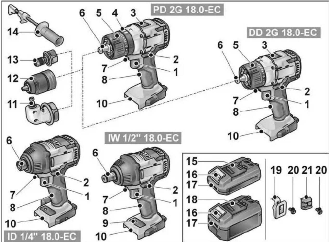
1 Trigger switch
For switching on and off and for accelerating up to maximum rotational speed
2 Direction preselector switch
3 Speed selector switch
4 Turning dial for operating mode (PD... only)
5 Turning dial for torque setting
6 Tool holder
7 Workplace lighting
8 Handle
9 Speed control panel
10 Insertion slot for battery
11 Angle attachment with release ring
12 Exchange chuck with release ring
13 Bit holder attachment with release ring
14 Auxiliary handle
15 Li-ion battery (2.5 Ah)
16 Release button for battery
17 State of charge indicator
18 Li-ion battery (5.0 Ah)
19 Belt clip
20 Fastening screw
21 Bit bracket
Instructions for use
Before initial operation
■ Unpack the power tool and accessories and check that no parts are missing or damaged.
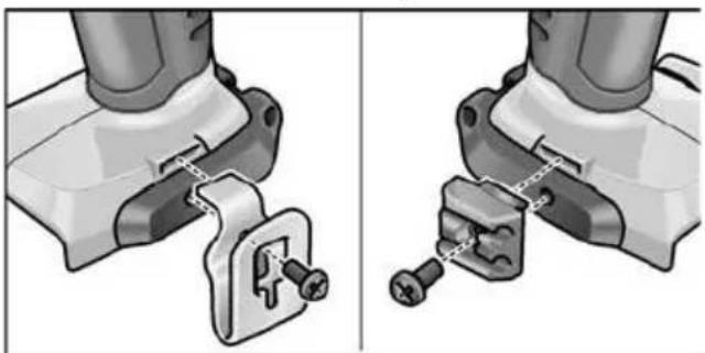
■ Attach the belt clip and bit holder with the enclosed fastening screw.
natural_image
Mechanical assembly diagram showing two views of a clamp or bracket device (no text or symbols present)i NOTE
The batteries are not fully charged on delivery. Prior to initial operation, charge the batteries fully. See "Charger/Charging process".
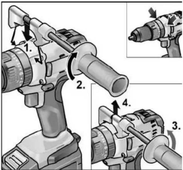
Fitting/removing the auxiliary handle (PD/DD 2G 18.0-EC)
CAUTION!
Use auxiliary handles if these are supplied with the power tool. The loss of control may result in injuries.
Changeable drill chuck BF 18.0-EC
CAUTION!
Before carrying out any work on the power tool, move the direction preselector switch (2) to the middle position.
Assemble
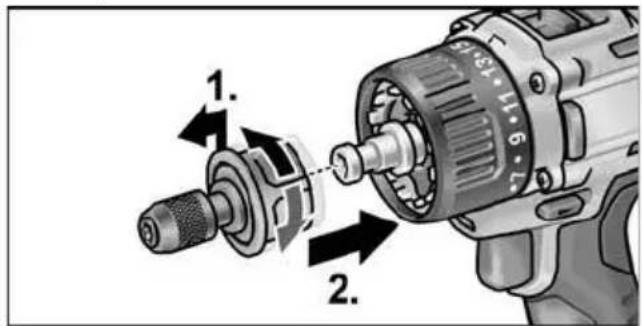
■ Pull unlocking ring forwards (1.) and press the drill chuck all the way onto the tool holder (2.).
■ Release unlocking ring. Check that the drill chuck is locked in position.
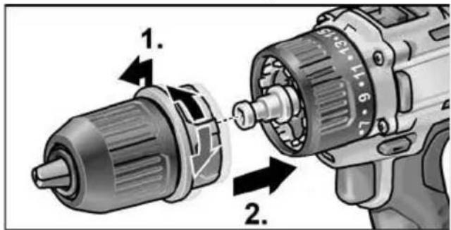
Disassemble
■ Pull unlocking ring forwards and remove the drill chuck.
Inserting the tools
Drill bits with a diameter of 1.5–13 mm, 12 " screwdriver bits and 12 " bit holders are securely held in the drill chuck.
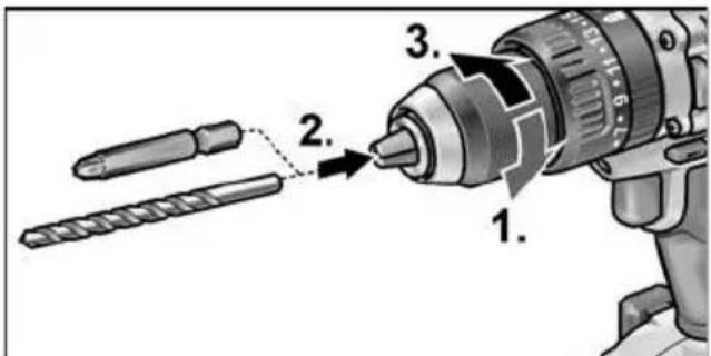
■ Grip the power tool firmly with one hand and turn the chuck with the other hand.
– Turn counterclockwise to open the chuck further.
– Turn clockwise to close the chuck.
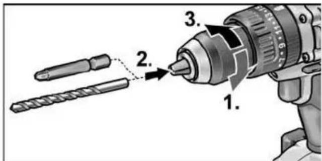
- Insert the tool.
■ Close the chuck fully.
i NOTE
Carry out a test run to check that the tool is chucked in the centre.
Angle attachment WV 18.0-EC

CAUTION!
Before carrying out any work on the power tool, move the direction preselector switch (2) to the middle position.
The angle attachment facilitates working in places which are difficult to access.
The angle attachment can be locked in different 30^ angular positions.
Assemble
■ Pull unlocking ring forwards (1.) and press angle attachment all the way onto the tool holder (2.).
■ Lock angle attachment in the required angular position.
■ Release unlocking ring. Check that the attachment is locked in position.
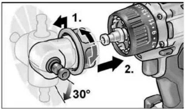
Disassemble
■ Pull unlocking ring forwards and remove angle attachment.
Inserting the tools
The angle attachment has a 12 " tool holder. Screwdriver bits and bit holders are securely held in the tool holder.
The keyless chuck (see "Changeable drill chuck BF 18.0-EC") or the bit holder (see "Bit holder attachment BV 18.0-EC") can be mounted on the angle attachment.
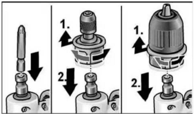
Bit holder attachment BV 18.0-EC

CAUTION!
Before carrying out any work on the power tool, move the direction preselector switch (2) to the middle position.
Assemble
■ Pull unlocking ring forwards (1.) and press bit holder attachment all the way onto the tool holder (2.).
■ Release unlocking ring. Check that the bit holder attachment is locked in position.
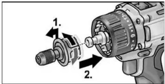
Disassemble
■ Pull unlocking ring forwards and remove bit holder attachment.
Inserting the tools
The bit holder attachment has a 12 " tool holder. Screw-driver bits are securely held in the tool holder.
■ Pull tool lock forwards (1.) and press in the tool all the way (2.).
■ Release tool lock.
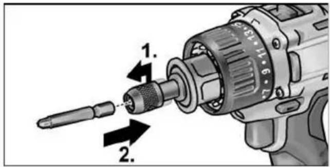
■ To remove the tool, pull tool lock backwards.
Tool change

CAUTION!
Before carrying out any work on the power tool, move the direction preselector switch (2) to the middle position.
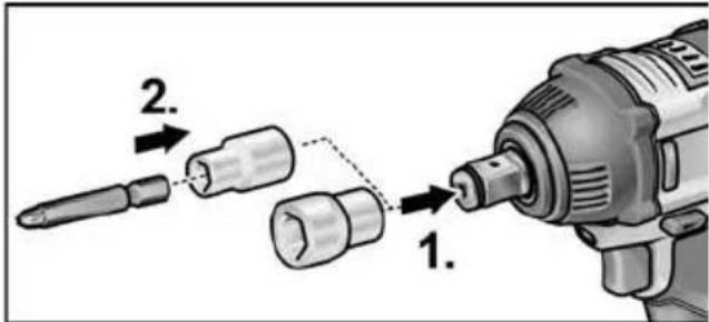
IW 1/2" 18.0-EC:
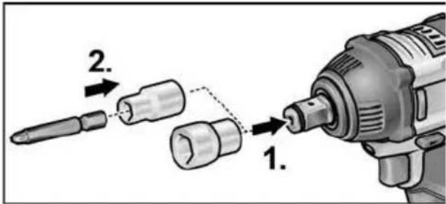
■ Push adapter on square drive of impact driver (1.).
■ Insert tool in adapter (2.).
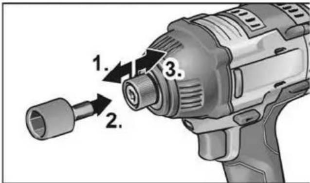
ID 1/4" 18.0-EC:
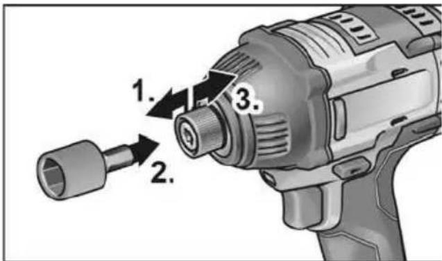
■ Pull tool lock forwards (1.) and press in the tool all the way (2.).
■ Release tool lock.
■ To remove the tool, pull tool lock backwards (3.).
Inserting/replacing the battery
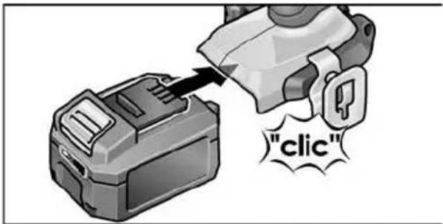
■ Press the charged battery into the power tool until it clicks into place.
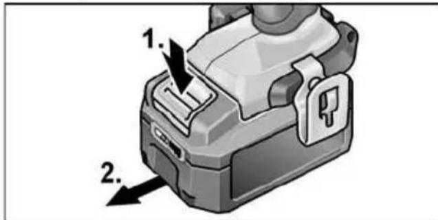
■ To remove, press the release button (1.) and pull out the battery (2.).

CAUTION!
Protect the battery contacts when the battery is not being used. Loose metal parts may short-circuit the contacts – Explosion and fire hazard!
Battery state of charge
■ Press the button to check the state of charge at the state of charge indicator LEDs.
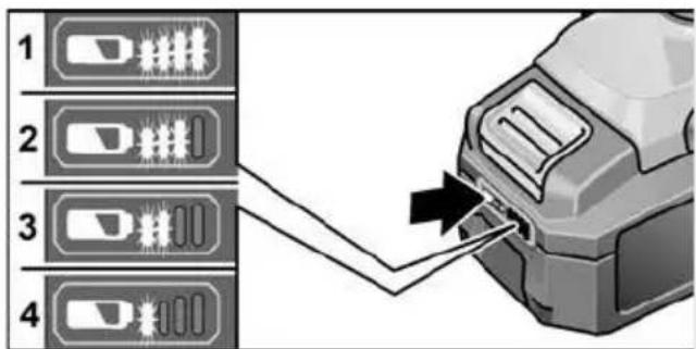
The indicator goes out after 5 seconds. If one of the LEDs flashes, the battery must be recharged. If none of the LEDs light up after the button is pressed, the battery is faulty and must be replaced.
Direction preselection

CAUTION!
Change the direction of rotation only when the power tool is stopped.

■ Move the direction preselector switch to the required position:
- Left: counterclockwise (remove screws, release screws)
- Right: clockwise (drill, insert screws, tighten down screws)
- Middle: switch-on interlock (tool change, when working on the power tool)
Operating mode
(PD 2G 18.0-EC only)

CAUTION!
Change the operating mode only when the power tool is stopped.
■ Move the operating mode turning dial to the required position.
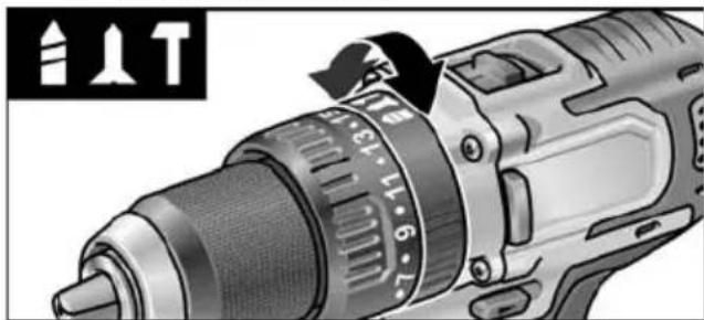
natural_image
Close-up of a drill bit with caliper and adjustment knob (no visible text or symbols)
Drilling

Screwing

Impact drilling
Torque preselection

CAUTION!
Change the torque only when the power tool is stopped.
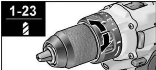
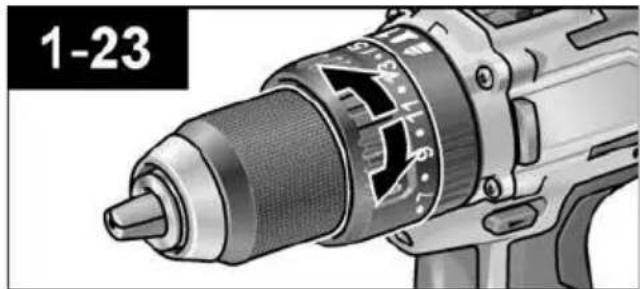
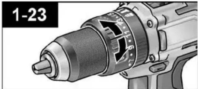
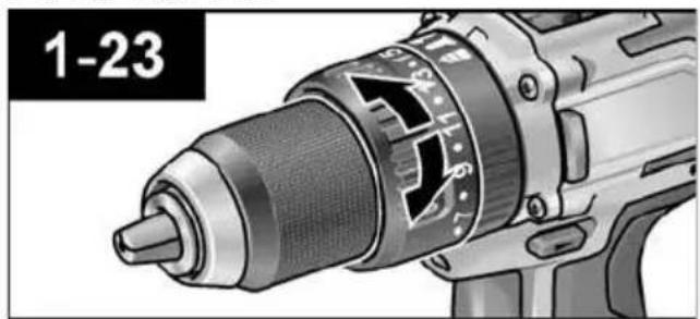
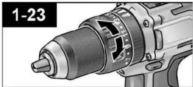
■ Move the torque setting turning dial to the required position.
DD 2G 18.0-EC:
natural_image
Close-up of a drill bit with visible screw and shaft (no text or symbols)1–23: Screwing

Drilling

NOTE
The safety clutch is deactivated in the
Drilling setting
PD 2G 18.0-EC:
natural_image
Close-up of a power drill bit with visible screw and head (no text or symbols)Speed preselection

CAUTION!
Change the speed only when the power tool is stopped.
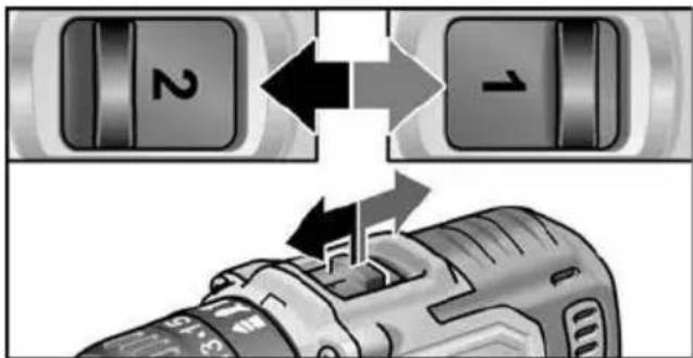
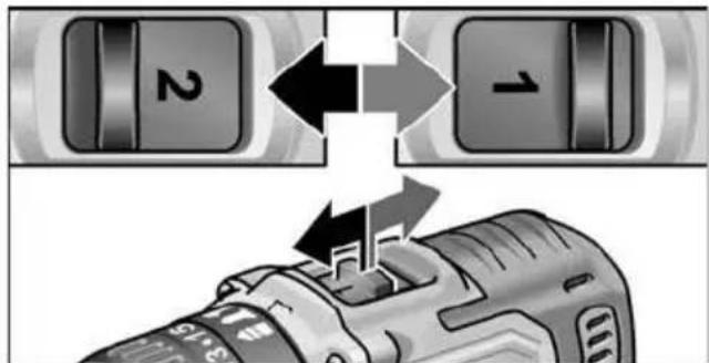
■ Move the selector switch to the required stage:
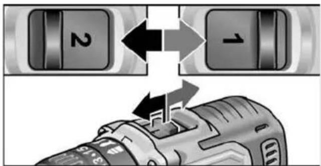
1: Low speed, high torque
2: High speed, low torque
Switching on the power tool
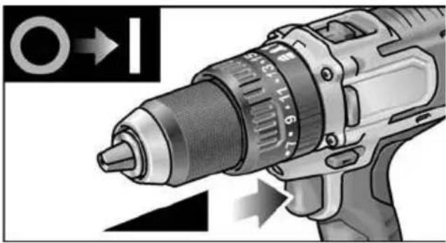
To switch the power tool on:
■ Press the trigger switch.
The power tool trigger switch allows the operator to increase the speed in increments up to the maximum speed.
natural_image
Close-up of a drill bit with a circular head indicator and directional arrows (no text or symbols on the tool itself)To switch the power tool off:
■ Release the trigger switch.
i NOTE
- The power tool is equipped with a brake which stops the cutting accessory as soon as the trigger switch is released.
- When using the power tool continuously, the operator should work primarily with the trigger switch fully depressed.
Workplace lamp on/off switch
- Turn direction of rotation preselector switch (2) to "Forwards" or "Reverse".
- Press electric tool on/off switch (1)
- Workplace lamp lights up
- Release electric tool on/off switch (1)
- Workplace lamp goes out automatically after approx. 10 sec.
Speed and torque preselector switch IW 1/2" 18.0-EC / ID 1/4" 18.0-EC
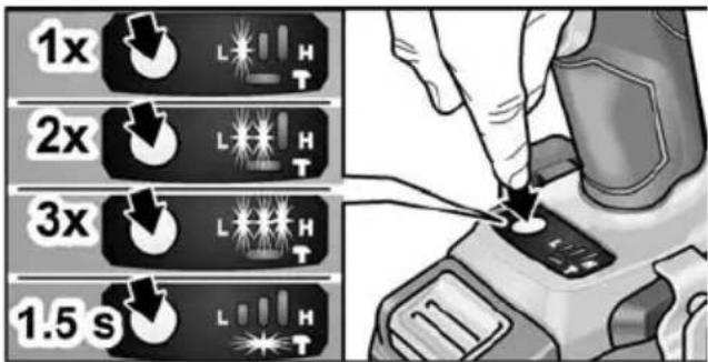
Change speed/torque
- Activate on/off switch (1)
- Press mode switch briefly (approx. 0.5 sec.).
- An LED lights up - torque:
IW 1/2" 18.0-EC: 150 Nm / 1500 rpm
ID 1/4" 18.0-EC: 60 Nm / 1500 rpm
- Press mode switch briefly
- Two LEDs light up - torque:
IW 1/2" 18.0-EC: 180 Nm / 2000 rpm
ID 1/4" 18.0-EC: 105 Nm / 2000 rpm
- Press mode switch briefly
- Three LEDs light up - torque:
IW 1/2" 18.0-EC: 250 Nm / 2500 rpm
ID 1/4" 18.0-EC: 225 Nm / 2500 rpm
- Press mode switch briefly
- An LED lights up - torque switches back to:
IW 1/2" 18.0-EC: 150 Nm
ID 1/4" 18.0-EC: 60 Nm
Torque can be increased again as described. During reverse operation of the electric tool – which only has one speed – the LEDs in the base go out automatically.
Change single impact mode to impact driver mode
■ Press mode switch for approx.
1.5 seconds.
- LED mode indicator lights up - single impact mode active
- LED mode indicator not lit - impact driver mode active.
Working with the power tool
CAUTION!
Before carrying out any work on the power tool, move the direction preselector switch (2) to the middle position.
i NOTE
To facilitate handling of the appliance when inserting screws, the screwdriver bit can be inserted directly into the tool holder of the appliance.
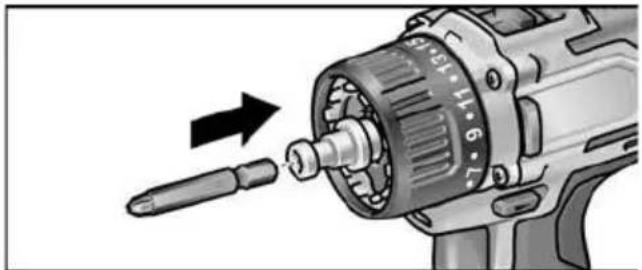
natural_image
Illustration of a drill bit being inserted into a motor, showing the shaft and gear (no text or symbols)- Assemble the tool head (drill chuck, angle attachment, bit holder attachment).
- Insert the battery.
- Insert the tool (drill bits, srewdriver bits, bit holders).
- Set operating mode according to the work item (PD ... only).
- Set torque preselection to the required setting.
- Set speed to the required setting.
- Set the required direction of rotation.
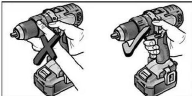
- Hold the power tool with one hand on the handle and assume the working position. If the power tool is running, never actuate the direction preselector switch or torque setting turning dial.
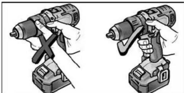
natural_image
Illustration of two hands using a drill press to adjust the drill (no text or symbols present)- Switch on the power tool.
At the end of work:
-
Release the trigger switch.
-
Move the direction preselector switch (2) to the middle position.
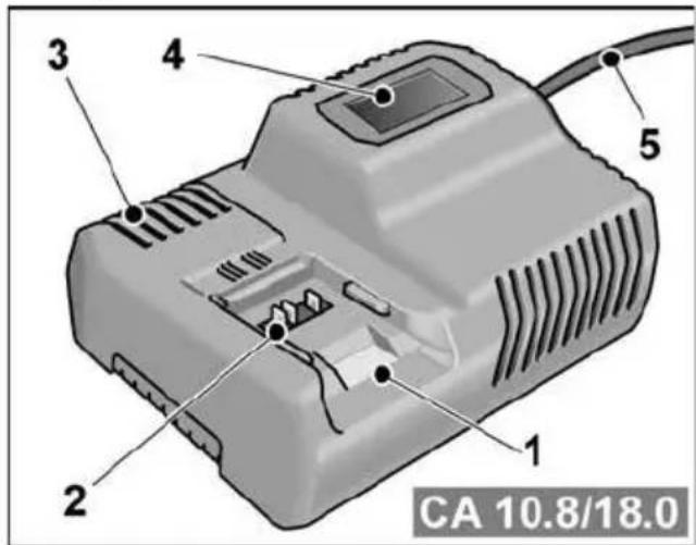
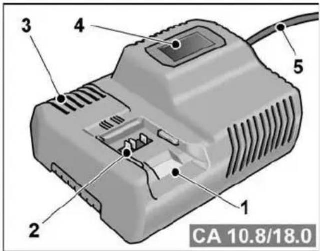
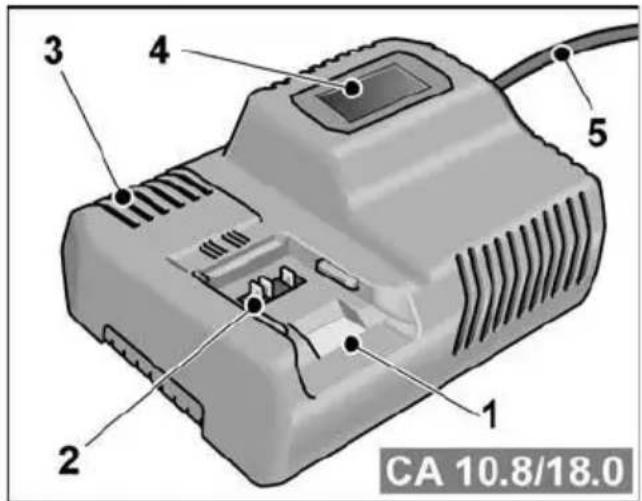
Charger
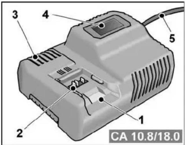
1 Insertion slot for battery
2 Contacts
3 Ventilation slots
4 Operating state display
5 Power cord with mains plug
The CA 10.8/18.0 charger is designed to charge FLEX batteries of the following types
- AP 10.8 (2.5 Ah),
- AP 18.0 (2.5 Ah),
- AP 10.8 (5.0 Ah),
- AP 18.0 (5.0 Ah).
Tips for a long battery service life
CAUTION!
- Never charge batteries at temperatures below 0 °C or above 55 °C.
- Do not charge batteries in environments with high air humidity or ambient temperature
- Do not cover batteries and the charger during the charging process.
– Pull out the charger mains plug at the end of the charging process.
Battery and charger heat up during the charging process. This is perfectly normal! Lithium-ion batteries do not exhibit the established “memory effect”. Nevertheless, a battery should be completely discharged before charging and the charging process should always be fully completed.
If batteries are not used for an extended period of time, store them partially charged in a cool place.
Charging process

CAUTION!
Insert only original batteries in the supplied charger.
■ Insert the charger mains plug. The display backlighting lights up green for 2 seconds and then goes out again. OK is displayed.

■ Insert the battery fully into the charger until it clicks into place.
- The time remaining in the charging process (until the battery is fully charged) and a graphic representation of the state of charge are shown alternately in the display.
- The display backlighting lights up orange when the battery is charged less than 80%.
- When the battery charge reaches 80% the display lights up green and OK is indicated.
■ The battery is fully charged when the display appears.
The green backlighting goes out after a short time.
■ Remove the battery from the charger.
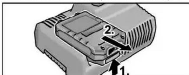
■ Pull out the mains plug.

NOTE
If the display flashes after the battery is inserted in the charger, there is a fault in the battery or in the charger.
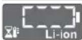
Display flashes slowly. Backlighting orange.
The battery is too hot or too cold. The charging process starts when the battery reaches the charging temperature ( 0^ ...55°C).
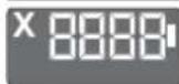
Display flashes rapidly. Backlighting red.
Remove the battery from the charger and insert again. If the same display persists, the battery is faulty. Replace the battery or have it checked at an authorised repair shop.
If this error message is displayed again with a different battery, this indicates that there is a fault in the charger. Have the charger checked at an authorised repair shop.
Maintenance and care
Cleaning

WARNING!
If metals are worked over a prolonged period, electroconductive dust may become deposited inside the housing. Clean the power tool and ventilation slots at regular intervals. Frequency of cleaning is dependent on the material machined and the duration of use.
■ Regularly blow out the housing interior and motor with dry compressed air. Keep the power tool running while doing this.
Charger

WARNING!
Before performing any work, pull out the mains plug. Do not use water or liquid detergents.
■ Remove dirt and dust from the housing with a brush or a dry cloth.
Repairs
Repairs may be carried out by an authorised customer service centre only.
Spare parts and accessories
For other accessories, in particular cutting accessories, please refer to the manufacturer's catalogues.
Exploded drawings and spare-part lists can be found on our homepage: www.flex-tools.com
Transport
The lithium equivalent content of the batteries contained in the scope of delivery is below the relevant limit values. Therefore the battery as a separate component and the power tool with its scope of delivery are not subject to national or international dangerous goods regulations. If several devices containing lithium-ion batteries are transported, these regulations may become relevant and require special safety measures (e.g. for the packaging). In this case acquaint yourself with the regulations that apply to the country of use.
CE conformity
We declare on our sole responsibility that the product described in "Technical data" conforms to the following standards or normative documents:
EN 62841 according to the provisions of Directives 2014/30/EU, 2006/42/EC, 2011/65/EU.
Responsible for technical documents: FLEX-Elektrowerkzeuge GmbH, R & D Bahnhofstrasse 15, D-71711 Steinheim/Murr
Eckhard Rühle
Manager Research &
Development (R & D)
Klaus Peter Weinper
Head of Quality
Department (QD)
- mains operated power tool by removing the power cord,
- battery operated power tool by removing the battery.

EU countries only.
Do not dispose of electric power tools in the household waste! In accordance with the European Directive 2012/19/EU on Waste Electrical and Electronic Equipment and its incorporation into national law, used power tools must be collected separately and recycled in an environmentally friendly manner.

Raw material recovery instead of waste disposal.
Device, accessories and packaging should be recycled in an environmentally friendly manner. Plastic parts are identified for recycling according to material type.
WARNING!
Do not throw batteries into the household waste, fire or water. Do not open disused batteries.
Accumulators/batteries should be collected, recycled or disposed of in an environmentally friendly manner.

EU countries only.
In accordance with the European Directive 2006/66/EC on Waste Electrical and Electronic Equipment and its incorporation into national law, defective or used batteries must be collected separately and recycled in an environmentally friendly manner.
i NOTE
Please ask your dealer about disposal options.
Exemption from liability
The manufacturer and his representative are not liable for any damage and lost profit due to interruption in business caused by the product or by an unusable product. The manufacturer and his representative are not liable for any damage which was caused by improper use of the product or by use of the product with products from other manufacturers.
Table des matières
natural_image
Mechanical assembly diagram showing two views of a tool with screws and a bracket (no text or symbols)Mandrin de perçage interchangeable BF 18.0-EC
PRUDENCE!
Démontage
Adaptateur porte-embout BV 18.0-EC
PRUDENCE!
Démontage
natural_image
Illustration of a drill bit with a 12-inch speed and control knob (no text or symbols): perçage
: vissage
natural_image
Close-up of a mechanical drill bit with visible teeth and screw head (no text or symbols)1–23 : vissage
: perçage
i REMARQUE
natural_image
Close-up of a power drill bit with visible branding and model number 1-23 (no text or symbols on the drill itself)natural_image
Close-up of a power drill with a circular head indicator and directional arrows (no text or symbols on the drill itself)natural_image
Close-up of a drill bit being inserted into a motor, showing the shaft and head (no text or symbols visible)natural_image
Illustration of two hands using a drill press to adjust the drill (no text or symbols present)- Allumez l'appareil.
Klaus Peter Weinper Head of Quality Department (QD)
18.12.2017
natural_image
Mechanical assembly diagrams showing two views of a tool with fasteners and connectors (no text or symbols)i AVVERTENZA
Mandrino intercambiabile BF 18.0-EC
PRUDENZA!
Smontaggio
Smontaggio
natural_image
Close-up of a mechanical power drill bit with no visible text or symbols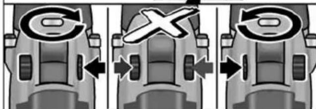
natural_image
Close-up of a mechanical power drill with a caliper and adjustment knob (no visible text or symbols)
Foratura

Avvitatura

natural_image
Close-up of a drill bit with visible teeth and internal components (no text or symbols)1–23: Avvitatura

Foratura

AVVERTENZA
natural_image
Close-up of a power drill bit with visible screw and adjustment dial (no text or symbols)natural_image
Close-up of a power drill with a circular head indicator and directional arrow (no text or symbols on the drill itself)natural_image
Illustration of a drill bit being inserted into a motor, showing the shaft and gear (no text or symbols)natural_image
Illustration of two hands using a drill press to adjust the drill (no text or symbols present)natural_image
Mechanical assembly diagram showing two views of a mechanical clamp or bracket (no text or symbols present)Portabrocas intercambiable BF 18.0-EC
¡CUIDADO!
Desmontaje
Adaptador portabrocas BV 18.0-EC

¡CUIDADO!
Desmontaje
natural_image
Close-up of a black-and-white illustration of a power drill with a circular dial and adjustment knobs (no text or symbols visible)
: Taladrar

: Atornillar

natural_image
Close-up of a drill bit with visible teeth and screw head (no text or symbols)1–23: Atornillar

Taladrar

NOTA
natural_image
Close-up of a drill bit with visible branding and no readable text or symbolsnatural_image
Close-up of a power drill with a circular head and adjustment arrows indicating tool path (no text or symbols)natural_image
Close-up of a drill bit with a screwdriver inserted, showing mechanical components and an arrow indicating motion (no text or symbols)natural_image
Illustration of two hands using a drill press, showing the tool being inserted (no text or symbols present)- AP 10.8 (2,5 Ah),
- AP 18.0 (2,5 Ah),
- AP 10.8 (5,0 Ah),
- AP 18.0 (5,0 Ah).
Eckhard Rühle Manager Research & Development (R & D)
Klaus Peter Weinper Head of Quality Department (QD)
18.12.2017
natural_image
Mechanical assembly diagram showing a clamp and bracket component (no text or symbols visible)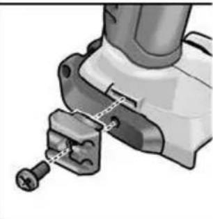
natural_image
Mechanical assembly diagram showing a tool interacting with a bracket (no text or symbols visible)i INDICAÇÃO
Desmontar
■ Aplicar a ferramenta.
■ Fechar completamente o mandril.
i INDICAÇÃO
Desmontar
natural_image
Close-up of a mechanical power drill with caliper and adjustment knobs (no visible text or symbols)natural_image
Close-up of a drill bit with visible teeth and internal components (no text or symbols)1–23: Aparafusar
Furar
i INDICAÇÃO
natural_image
Close-up of a power drill bit with visible branding and model number 1-23 (no text or symbols on the drill itself)natural_image
Close-up of a power drill with visible blade and drum, showing tool movement (no text or symbols)natural_image
Illustration of a drill bit being inserted into a motor, showing the shaft and gear (no text or symbols)natural_image
Illustration of two hands using a drill press to adjust the drill (no text or symbols present)- Ligar o aparelho.
Eckhard Rühle Manager Research & Development (R & D)
Klaus Peter Weinper Head of Quality Department (QD)
DD 2G 18.0-EC is bestemd
PD 2G 18.0-EC is bestemd
natural_image
Mechanical assembly diagram showing two views of a clamp or bracket mechanism (no text or symbols)Demonteren
Demonteren
natural_image
Close-up of a drill bit with caliper and screwdriver (no visible text or symbols)
: Boren

: Schroeven

: Slagboren
natural_image
Close-up of a mechanical drill bit with no visible text or symbols1–23: Schroeven

Boren

LET OP
natural_image
Close-up of a power drill bit with visible branding and model number 1-23 (no text or symbols on the drill itself)Snelheidsselectie

VOORZICHTIG!
natural_image
Close-up of a drill bit with a circular head indicator and directional arrows (no text or symbols on the tool itself)natural_image
Illustration of a drill bit being inserted into a motor, showing the shaft and gear (no text or symbols)natural_image
Illustration of two hands using a drill press, showing the correct and incorrect states (no text or symbols present)Eckhard Rühle
Manager Research & Development (R & D)
Klaus Peter Weinper
Head of Quality Department (QD)
18.12.2017
natural_image
Mechanical assembly diagram showing two views of a clamp or bracket device (no text or symbols present)i BEMAERK
Vekselpatron BF 18.0-EC
! FORSIGTIG!
Afmontering
Bitholderforsats BV 18.0-EC

FORSIGTIG!
Afmontering

FORSIGTIG!
natural_image
Close-up of a mechanical power drill with caliper and adjustment knobs (no visible text or symbols)
B o r i n g

: Skruning

: Slagboring
Momentvalg

FORSIGTIG!
natural_image
Close-up of a drill bit with visible mesh and adjustment knob (no text or symbols)1–23: Skruning

Boring

BEMAERK
I borestilling er glidekoblingen deaktiveret.
PD 2G 18.0-EC:
natural_image
Close-up of a power drill bit with visible screw and head (no text or symbols)Hastighedsforvalg

FORSIGTIG!
natural_image
Close-up of a power drill with a circular head indicator and directional arrow (no text or symbols on the drill itself)Slukke maskinen:
■ Slip afbryderen.
i
BEMAERK
natural_image
Close-up of a drill bit with a screwdriver inserted, showing mechanical components and an arrow indicating motion (no text or symbols present)natural_image
Illustration of two hands using a drill press, showing tool positioning (no text or symbols)- Tænd maskinen.
Klaus Peter Weinper Head of Quality Department (QD)
18.12.2017
natural_image
Mechanical assembly diagram showing two views of a clamp or bracket mechanism (no text or symbols)i HENVISNING
Skiftechuck BF 18.0-EC
FORSIKTIG!
Demontering
Bitsholderforsats BV 18.0-EC

FORSIKTIG!
Demontering
natural_image
Close-up of a black-and-white photo of a power drill with visible caliper and adjustment knobs (no text or symbols)Boring
: Skruing
T: Slagboring
Dreiemomentforvalg

FORSIKTIG!
natural_image
Close-up of a mechanical drill bit with visible mesh and internal components (no text or symbols)1–23: Skruer
Boring
i HENVISNING
I bore-stilling for slure-koblingen deaktivert.
PD 2G 18.0-EC:
natural_image
Close-up of a power drill bit with visible screw and head (no text or symbols)Hastighetsforvalg
FORSIKTIG!
natural_image
Close-up of a power drill with visible blade and drum, showing tool movement (no text or symbols)natural_image
Illustration of a drill bit being inserted into a motor, showing the shaft and gear (no text or symbols)natural_image
Illustration of two hands using a drill press, showing the blade and handle (no text or symbols present)- Apparatet slås på.
- AP 10.8 (2,5 Ah),
- AP 18.0 (2,5 Ah),
- AP 10.8 (5,0 Ah),
- AP 18.0 (5,0 Ah).
Henvisninger for lang batteri-levetid

FORSIKTIG!
natural_image
Mechanical assembly diagram showing two views of a clamp or bracket mechanism (no text or symbols)Snabbchuck BF 18.0-EC
VAR FÖRSIKTIG!
Demontera
Demontera
natural_image
Close-up of a drill bit with caliper and adjustment knob (no visible text or symbols)Borning
: Skruvning
T: Slagborrning
natural_image
Close-up of a drill bit with visible screw and shaft (no text or symbols)1–23: Skruvning

Borning

OBS!
natural_image
Close-up of a power drill bit with visible screw and head (no text or symbols)natural_image
Close-up of a drill bit with a circular head indicator and directional arrows (no text or symbols)natural_image
Illustration of a drill bit being inserted into a motor, showing the shaft and head (no text or symbols present)natural_image
Illustration of two hands using a drill press to adjust the drill (no text or symbols present)- AP 10.8 (2,5 Ah),
- AP 18.0 (2,5 Ah),
- AP 10.8 (5,0 Ah),
- AP 18.0 (5,0 Ah).
Eckhard Rühle Manager Research & Development (R & D)
Klaus Peter Weinper Head of Quality Department (QD)
18.12.2017
natural_image
Mechanical assembly diagram showing two views of a tool with clamping mechanism (no text or symbols)i OHJE
Irrotus
Irrotus
natural_image
Close-up of a mechanical power drill bit with a screw and adjustment knob (no visible text or symbols)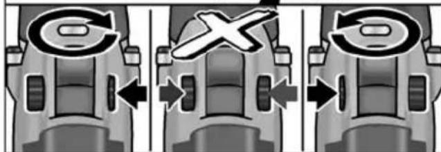
natural_image
Illustration of a drill bit with caliper and screwdriver (no text or symbols)
Poraaminen

Ruuvaaminen

Poraaminen iskulla
natural_image
Close-up of a drill bit with mesh head and control buttons (no visible text or symbols)1–23: Ruuvaaminen

Poraaminen

OHJE
natural_image
Close-up of a power drill bit with visible screw and head (no text or symbols)Nopeuden esivalinta

VARO!
natural_image
Close-up of a power drill with visible caliper and adjustment arrows (no text or symbols)Koneen pysäytys:
natural_image
Illustration of a drill bit being inserted into a motor, showing the shaft and rotor (no text or symbols)natural_image
Illustration of two hands using a drill press to adjust the drill (no text or symbols present)- Käynnistä kone.
Töiden jälkeen:
- AP 10.8 (2,5 Ah),
- AP 18.0 (2,5 Ah),
- AP 10.8 (5,0 Ah),
- AP 18.0 (5,0 Ah).
Klaus Peter Weinper Head of Quality Department (QD)
18.12.2017
natural_image
Mechanical assembly diagram showing a clamp and bracket assembly (no text or symbols visible)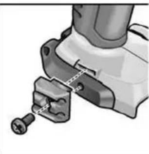
natural_image
Mechanical assembly diagram showing a tool interacting with a bracket and screw (no text or symbols visible)i YΠΟΔΕΙΞΗ
Αφαίρεση
Αφαίρεση
natural_image
Close-up of a black-and-white photo of a power drill with visible caliper and adjustment knobs (no text or symbols)
Τρύπημα

: Bíδωμα

: Τρύπημα με κρούση
natural_image
Close-up of a drill bit with visible screw and shaft (no text or symbols)1–23: Відшма

Τρύπημα

ΥΠΟΔΕΙΞΗ
natural_image
Close-up of a drill bit with visible screw and handle (no text or symbols)natural_image
Close-up of a power drill with visible screw and head, showing tool movement (no text or symbols)natural_image
Illustration of a drill bit being inserted into a motor, showing the shaft and gear (no text or symbols)natural_image
Illustration of two hands using a drill press to adjust the drill (no text or symbols present)1 Υποδοχή μπαταρίας
2 E π α φ έ ζ
3 Σχισμές αερισμού
- AP 10.8 (2,5 Ah),
- AP 18.0 (2,5 Ah),
- AP 10.8 (5,0 Ah),
- AP 18.0 (5,0 Ah).
natural_image
Mechanical assembly diagram showing a clamp and bracket component (no text or symbols visible)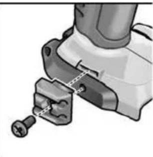
natural_image
Mechanical assembly diagram showing a tool interacting with a bracket (no text or symbols visible)i BİLGİ
Sökme
Sökülmesi
natural_image
Close-up of a black-and-white illustration of a drill bit with a circular dial and control knob (no text or symbols visible)
Delme

Vidalama

Darbeli delme
Tork ön seçimi

DİKKAT!
natural_image
Close-up of a drill bit with visible screw and shaft (no text or symbols)1–23: Vidalama

Delme

BİLGİ
natural_image
Close-up of a power drill bit with visible teeth and control buttons (no text or symbols)Hız ön seçimi

DİKKAT!
natural_image
Close-up of a drill bit with a circular head indicator and directional arrows (no text or symbols on the tool itself)natural_image
Close-up of a drill bit being inserted into a motor, showing the shaft and head (no text or symbols visible)natural_image
Illustration of two hands using a drill press to adjust the drill (no text or symbols present)- Cihazı açın.
Çalışma sonunda:
- AP 10.8 (2,5 Ah),
- AP 18.0 (2,5 Ah),
- AP 10.8 (5,0 Ah),
- AP 18.0 (5,0 Ah).
Eckhard Rühle
Manager Research &
Development (R & D)
Klaus Peter Weinper
Head of Quality
Department (QD)
natural_image
Mechanical assembly diagrams showing two views of a tool with fasteners and fasteners (no text or labels)i WSKAZÓWKA
Wymienny uchwyt wiertarski BF 18.0-EC
OSTROŻNIE!
Demontaż
Demontaż
natural_image
Close-up of a drill bit with caliper and adjustment knob (no visible text or symbols)
: wiercenie

: wkręcanie

: wiercenie udarowe
natural_image
Close-up of a drill bit with visible screw and shaft (no text or symbols)1–23: wkręcanie

wiercenie

WSKAZÓWKA
natural_image
Close-up of a power drill bit with visible teeth and control knob (no text or symbols)natural_image
Close-up of a drill bit with a circular head indicator and directional arrow (no text or symbols on the tool itself)natural_image
Close-up of a drill bit with a screwdriver inserted, showing the tool's head and shaft (no text or symbols visible)natural_image
Illustration of two hands using a drill press, showing mechanical components and tool positioning (no text or symbols)- Włączyć urządzenie.
1 Gniazdo na akumulator
2 Kontakty
Eckhard Rühle Manager Research & Development (R & D)
Klaus Peter Weinper Head of Quality Department (QD)
18.12.2017
natural_image
Mechanical assembly diagram showing two views of a tool with clamping mechanism (no text or symbols)i MEGJEGYZÉS
Leszerelés
Leszerelés
natural_image
Close-up of a drill bit with caliper and adjustment knobs (no visible text or symbols)
Fúrás

Csavarozás

Ütvefúrás
natural_image
Close-up of a drill bit with visible screw and shaft (no text or symbols)1–23: Csavarozás

Fúrás

MEGJEGYZÉS
natural_image
Close-up of a power drill bit with visible branding and no readable text or symbolsnatural_image
Close-up of a drill bit with a circular head indicator and directional arrows (no text or symbols on the tool itself)A gép kikapcsolása:
natural_image
Illustration of a drill bit being inserted into a motor, showing the shaft and gear (no text or symbols)natural_image
Illustration of two hands using a drill press, showing tool positioning (no text or symbols)Eckhard Rühle Manager Research & Development (R & D)
Klaus Peter Weinper Head of Quality Department (QD)
-
- 18.
natural_image
Mechanical assembly diagram showing two views of a clamp or bracket mechanism (no text or symbols)Demontáž
Demontáž
natural_image
Close-up of a drill bit with visible caliper and adjustment knob (no text or symbols)
: vrtání

: šroubování

natural_image
Close-up of a drill bit with visible teeth and internal components (no text or symbols)1–23: šroubování

vrtání

UPOZORNĚNÍ
natural_image
Close-up of a power drill bit with visible screw and head (no text or symbols)Předvolba rychlosti

POZOR!
natural_image
Close-up of a power drill with a circular head indicator and tool handle (no text or symbols visible)Vypnutí nářadí:
■ Uvolněte spínač.
i UPOZORNĚNÍ
natural_image
Illustration of a drill bit being inserted into a motor, showing the shaft and gear (no text or symbols)natural_image
Illustration of two hands using a drill press, showing tool positioning (no text or symbols)- Zapněte nářadí.
Po ukončení práce:
Klaus Peter Weinper Head of Quality Department (QD)
18.12.2017
natural_image
Mechanical assembly diagram showing a tool interacting with a bracket and mounting bracket (no text or symbols visible)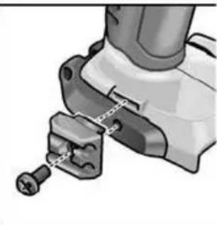
natural_image
Close-up of a mechanical tool with a spring and connecting rod (no visible text or symbols)i UPOZORNENIE
Demontáž
Nadstavec pre držiak hrotov BV 18.0-EC
POZOR!
Demontáž
■ Odblokovací krúžok potiahnite dopredu a odoberte nadstavec pre držiak hrotov.
Vloženie nástrojov
natural_image
Close-up of a drill bit with caliper and screwdriver (no visible text or symbols)
Vrtanie

Skrutkovanie

Príklepové vrtanie
natural_image
Close-up of a drill bit with visible teeth and screw head (no text or symbols)1–23: Skrutkovanie

Vítanie

UPOZORNENIE
natural_image
Close-up of a power drill bit with visible branding and model number 1-23 (no text or symbols on the drill itself)Predvoľba rýchlosti

POZOR!
natural_image
Close-up of a drill bit with a circular head indicator and directional arrows (no text or symbols on the tool itself)Vypnutie náradia:
■ Uvoľnite vypínač.
i UPOZORNENIE
natural_image
Illustration of a drill bit being inserted into a motor, showing the shaft and head (no text or symbols present)natural_image
Illustration of two hands using a drill press to adjust the drill (no text or symbols present)- Zapnite náradie.
Po ukončení práce:
-
Uvołnite vypínač.
-
Nastavte prepínač predvolby smeru otáčania (2) do strednej polohy.
Nabíjačka
Klaus Peter Weinper Head of Quality Department (QD)
18.12.2017
natural_image
Mechanical assembly diagram showing two views of a clamp or bracket mechanism (no text or symbols)i NAPOMENA
Prilikom isporuke akumulatori nisu potpuno napunjeni. Prije prvog puštanja u rad napunite do kraja akumulatore. U tu svrhu pogledajte „Punjač/Postupak punjenja“.
Montaža/demontaža dodatne ručke (PD/DD 2G 18.0-EC)
OPREZ!
Demontiranje
■ Prsten za deblokadu povucite prema naprijed i skinite steznu glavu.
Umetanje alata
■ Umetanje alata.
Držač nastavka BV 18.0-EC

OPREZ!
Prije svih radova na električnom alatu prekidač za odabir smjera okretanja (2) postavite u srednji položaj.
Montiranje
■ Prsten za deblokiranje povucite prema naprijed (1.) i držač nastavka do graničnika pritisnite u prihvat alata(2.).
■ Otpustite prsten za deblokadu. Provjerite dosjed.
Demontiranje
■ Za vađenje alata aretiranje alata povucite prema nazad.
Zamjena alata

OPREZ!
Prije svih radova na električnom alatu prekidač za odabir smjera okretanja (2) postavite u srednji položaj.
IW 1/2" 18.0-EC:
■ Nasadni ključ pritisnite na četverokutni prihvat udarnog izvijača (1.).
■ Umetnite alat u nasadni ključ (2.).
ID 1/4" 18.0-EC:
■ Aretiranje alata povucite prema naprijed (1.) i pritisnite alat do graničnika (2.).
■ Otpustite aretiranje alata.
■ Za vađenje alata aretiranje alata povucite prema nazad (3.).
natural_image
Close-up of a black-and-white photo of a power drill with visible caliper and adjustment knobs (no text or symbols)natural_image
Close-up of a drill bit with visible screw and shaft (no text or symbols)1–23: vijčanje
: bušenje
i NAPOMENA
U položaju za bušenje arlizna spojka je deaktivirana.
PD 2G 18.0-EC:
natural_image
Close-up of a power drill bit with visible screw and adjustment dial (no text or symbols)Odabir brzine
OPREZ!
Brzinu možete mijenjati samo kada je električni alat u stanju mirovanja.

flowchart
graph TD
    A["2"] --> B["1"]
    B --> C["Control Unit"]
    style A fill:#f9f,stroke:#333
    style B fill:#bbf,stroke:#333
    style C fill:#dfd,stroke:#333
■ Prekidač za odabir stavite na potrebni stupanj:
1: mala brzina, visoki okretni moment
2: velika brzina, nizak okretni moment
natural_image
Close-up of a power drill with a circular head indicator and tool handle (no text or symbols visible)natural_image
Close-up of a drill bit being inserted into a motor, showing the shaft and gear (no text or symbols visible)-
Montirajte nosač alata (zamjenska stezna glava, kutni nastavak, držač nastavka).
-
Umetnite akumulator.
- Umetnite alat (svrdlo, odvijač, držač nastavka).
- Način rada podesite sukladno radnom zadatku (samo PD...).
- Odabir okretnog momenta postavite na potrebni stupanj.
- Brzinu postavite na potrebni stupanj.
- Podesite potreban smjer okretanja.
- Električni alat primite rukom i zauzmite radni položaj.
Kada je motor u radu nikada ne pritišćite prekidač za odabir smjera okretanja odn. postavku okretnog momenta!
natural_image
Illustration of two hands using a drill press to adjust the drill (no text or symbols present)- Uključite aparat.
1 Otvor za umetanje akumulatora
2 Kontakti
3 Prorezi za ventilaciju
4 Zaslon za prikaz radnog stanja
5 Mrežni kabel s mrežnim utikačem
Punjač CA 10.8/18.0 namijenjen je za punjenje FLEX akumulatora tipa
- AP 10.8 (2,5 Ah),
- AP 18.0 (2,5 Ah),
- AP 10.8 (5,0 Ah),
- AP 18.0 (5,0 Ah).
Klaus Peter Weinper
Head of Quality
Department (QD)
18.12.2017
natural_image
Mechanical assembly diagram showing two views of a clamp or bracket device (no text or symbols present)i OPOMBA
Akumulatorske baterije ob dobavi niso popolnoma napolnjene. Pred prvo uporabo akumulatorske baterije popolnoma napolnite. V ta namen glejte poglavje „Polnilnik/Polnjenje“.
Izmenljiva vrtalna glava BF 18.0-EC
POZOR!
Demontaža
■ Obroč za deblokiranje povlecite naprej in snemite vrtalno glavo.
Vpenjanje nastavkov
V vrtalno glavo je mogoče vpeti svedre s premerom 1,5–13 mm, vijačne nastavke ^1/2 " in držala za nastavke ^1/2 ".
■ Z eno roko čvrsto držite električno orodje, z drugo pa vrtite vrtalno glavo.
– Z vrtenjem v nasprotni smeri urnega kazalca vrtalno glavo še bolj odprete.
– Z vrtenjem v smeri urnega kazalca vrtalno glavo zaprete.
■ Vstavite nastavek.
■ Vrtalno glavo popolnoma zaprite.
i OPOMBA
Vpetje za nastavke BV 18.0-EC

POZOR!
Demontaža
■ Da nastavek odstranite, blokado nastavka povlecite nazaj.
Menjava orodja IW

POZOR!
■ Stikalo za izbiro smeri vrtenja nastavite v želen položaj:
natural_image
Close-up of a mechanical power drill with caliper and adjustment knobs (no visible text or symbols)
: Vrtanje

: Vijačenje

: Udarno vrtanje
Izbira vrtilnega momenta

POZOR!
Vrtilni moment je dovoljeno spremeniti samo, ko električno orodje miruje.
natural_image
Close-up of a drill bit with mesh head and control knob (no visible text or symbols)1–23: Vijačenje

Vrtanje

OPOMBA
natural_image
Close-up of a power drill bit with visible screw and head (no text or symbols)Izbira hitrosti

POZOR!
Hitrost je dovoljeno spremeniti samo, ko električno orodje miruje.
natural_image
Close-up of a drill bit with a circular head indicator and directional arrows (no text or symbols on the tool itself)Izklop orodja:
■ Spustite stikalo.
i OPOMBA
natural_image
Close-up of a drill bit being inserted into a motor, showing the shaft and head (no text or symbols visible)natural_image
Illustration of two hands using a drill press, showing tool positioning (no text or symbols)- Vklopite orodje.
Po končanem delu:
- Spustite stikalo.
- Stikalo za izbiro smeri vrtenja (2) nastavite v osrednji položaj.
Polnilnik
- AP 10.8 (2,5 Ah),
- AP 18.0 (2,5 Ah),
- AP 10.8 (5,0 Ah),
- AP 18.0 (5,0 Ah).
■ Izvlecite vtič iz vtičnice.

OPOMBA
Eckhard Rühle Manager Research & Development (R & D)
Klaus Peter Weinper Head of Quality Department (QD)
18.12.2017
natural_image
Mechanical assembly diagram showing two views of a mechanical clamp or bracket (no text or symbols present)i INDICATIE
Demontarea
Introducerea sculelor
Introducerea sculelor
Cap aplicat cu suport de bituri BV 18.0-EC
PRECAUTIE!
Demontarea
Introducerea sculelor
natural_image
Close-up of a drill bit with caliper and adjustment knobs (no visible text or symbols)
: Găurire

: Înşurubare

natural_image
Close-up of a drill bit with visible teeth and screw head (no text or symbols)1–23: Înşurubare
: Găurire
i INDICATIE
natural_image
Close-up of a power drill bit with visible branding and model number 1-23 (no text or symbols on the drill itself)Preselectarea vitezei
PRECAUTIE!
natural_image
Close-up of a drill bit with a circular head indicator and directional arrows (no text or symbols)natural_image
Close-up of a drill bit being inserted into a motor, showing the shaft and rotor (no text or symbols visible)natural_image
Illustration of two hands using a drill press, showing tool positioning (no text or symbols)- Conectați aparatul.
- AP 10.8 (2,5 Ah),
- AP 18.0 (2,5 Ah),
- AP 10.8 (5,0 Ah),
- AP 18.0 (5,0 Ah).
EN 62841 conform prevederilor Directivei 2014/30/UE, 2006/42/CE, 2011/65/UE.
Responsabili pentru documente tehnice: FLEX-Elektrowerkzeuge GmbH, R & D Bahnhofstrasse 15, D-71711 Steinheim/Murr
Eckhard Rühle Manager Research & Development (R & D)
Klaus Peter Weinper Head of Quality Department (QD)
18.12.2017
natural_image
Mechanical assembly diagram showing a tool interacting with a bracket (no text or symbols visible)
natural_image
Mechanical assembly diagram showing a tool inserted into a bracket with screw fasteners (no text or symbols visible)i УКАЗАНИЕ
Демонтиране
Демонтиране
natural_image
Illustration of a drill bit with a 13-inch head and control buttons (no text or symbols on the tool itself): пробиване
: завинтване
T: ударно пробиване
natural_image
Close-up of a drill bit with mesh head and control buttons (no readable text or symbols)1–23: завинтване

пробиване

УКАЗАНИЕ
natural_image
Close-up of a power drill bit with visible screw and adjustment knob (no text or symbols)Избор на скорост

ВНИМАНИЕ!
natural_image
Close-up of a power drill with a circular head indicator and directional arrow (no text or symbols on the drill itself)natural_image
Illustration of a drill bit being inserted into a motor, showing the shaft and head (no text or symbols present)natural_image
Illustration of two hands using a drill press, showing tool positioning and application (no text or symbols)- Включете уреда.
Klaus Peter Weinper Head of Quality Department (QD)
natural_image
Mechanical assembly diagram showing two views of a tool with fasteners and mounting brackets (no text or symbols)i УКАЗАНИЕ
Снятие
Снятие
natural_image
Close-up of a black-and-white illustration of a drill bit with no visible text or symbols
сверление

заворачивание

ударное сверление
natural_image
Close-up of a mechanical drill bit with visible teeth and internal components (no text or symbols)1-23: заворачивание

верление

УКАЗАНИЕ
natural_image
Close-up of a power drill bit with visible screw and handle (no text or symbols)Выбор скорости

ВНИМАНИЕ!
natural_image
Close-up of a drill bit with a circular head indicator and directional arrow (no text or symbols on the tool itself)Выключение прибора:
natural_image
Close-up of a drill bit being inserted into a motor, showing the shaft and gear (no text or symbols visible)natural_image
Illustration of two hands using a drill press, showing tool positioning (no text or symbols)- Включите прибор.
- AP 10.8 (2,5 A*4),
- AP 18.0 (2,5 A*4),
- AP 10.8 (5,0 A*4),
- AP 18.0 (5,0 A*4).
Klaus Peter Weinper Head of Quality Department (QD)
18.12.2017
natural_image
Mechanical assembly diagram showing two views of a clamp or bracket mechanism (no text or symbols)Vahetatav padrun BF 18.0-EC
ETTEVAATUST!
Eemaldamine
Otsakuhoidikumanus BV 18.0-EC

ETTEVAATUST!
Eemaldamine
Tarviku eemaldamiseks tömmake tarvikufiksaatorit tahapoole.
Tööriistavahetus

ETTEVAATUST!
natural_image
Close-up of a drill bit with a screwdriver and handle (no visible text or symbols)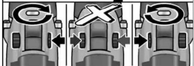
natural_image
Close-up of a drill bit with a 12-pin roller and control knob (no visible text or symbols): puurimine
: kruvikeeramine
1: löökpuurimine
natural_image
Close-up of a drill bit with visible teeth and internal components (no text or symbols)1–23: kruvikeeramine
: puurimine
i MÄRKUS!
natural_image
Close-up of a power drill bit with visible teeth and control knob (no text or symbols)Kiiruse eelvalik
ETTEVAATUST!
natural_image
Close-up of a power drill with a circular head indicator and directional arrow (no text or symbols on the drill itself)natural_image
Close-up of a drill bit being inserted into a motor, showing the shaft and head (no text or symbols visible)natural_image
Illustration of two hands using a drill press to adjust the drill (no text or symbols present)- Lülitage seade sisse.
1 Aku pesa
2 K o n t a k t i
Eckhard Rühle
Manager Research & Development (R & D)
Klaus Peter Weinper
Head of Quality
Department (QD)
natural_image
Mechanical assembly diagrams showing two views of a clamp or bracket mechanism (no text or symbols)i NURODYMAS
Greito keitimo griebtuvas BF 18.0-EC
ATSARGIA!!
Išmontavimas
Išmontavimas
natural_image
Illustration of a drill bit with control knob and rotary dial (no text or symbols)
grežimas

sukimas

smūginis gręžimas
Sukimo momento parinktis

ATSARGIA!!
natural_image
Close-up of a drill bit with visible internal components and a label '1-23' (no text or symbols on the drill bit itself)1–23: sukimas

grężimas

NURODYMAS
natural_image
Close-up of a power drill bit with visible screw and head (no text or symbols)Greičio parinktis

ATSARGIA!!
Greitj keiskite tik sustojus elektriniam jrankiui.
flowchart
graph TD
    A["Button 2"] --> B["Arrow Left"]
    C["Button 1"] --> D["Arrow Right"]
    E["Device Icon 5.0"] --> F["Arrow Down"]
    G["Device Icon 4.0"] --> H["Arrow Up"]
natural_image
Close-up of a drill bit with a circular head indicator and directional arrows (no text or symbols on the tool itself)natural_image
Illustration of a drill bit being inserted into a motor, showing the shaft and head (no text or symbols)natural_image
Illustration of two hands using a drill press to adjust the drill (no text or symbols present)- Prietaiso jjungimas.
Baigus darba: - Jungiklj atleiskite.
- Sukimosi krypties parinkimo jungiklj (2) nustatykite per vidurj.
Krovimo prietaisas
- AP 10.8 (2,5 Ah),
- AP 18.0 (2,5 Ah),
- AP 10.8 (5,0 Ah),
- AP 18.0 (5,0 Ah).
Eckhard Rühle
Manager Research &
Development (R & D)
Klaus Peter Weinper
Head of Quality
Department (QD)
18 Litija jonu akumulators (5,0 Ah)
19 Siksninas skava
natural_image
Mechanical assembly diagram showing two views of a tool with fasteners and connectors (no text or symbols)i NORĀDE
Demontāža
Demontāža
■ Lai iznemtu instrumentu, pavelciet instrumenta fiksatoru uz aizmuguri.
Instrumenta

UZMANĪBU!
natural_image
Close-up of a drill bit with a circular caliper and adjustment knob (no visible text or symbols)
Urbšana

Skrūvēšana

Urbšana ar triecienu
natural_image
Close-up of a drill bit with visible screw and head (no text or symbols)1–23: skrūvēšana

urbšana

NORÃDE
natural_image
Close-up of a power drill bit with visible screw and adjustment knob (no text or symbols)Ātruma izvēle

UZMANĪBU!
natural_image
Close-up of a drill bit with a circular head indicator and directional arrow (no text or symbols on the tool itself)Ierīces izslēgšana:
■ Atlaidiet slēdzi.
i NORÃDE
natural_image
Illustration of a drill bit being inserted into a motor, showing the shaft and head (no text or symbols)natural_image
Two illustrations of hands using a drill press to adjust the drill (no text or symbols visible)- leslēdziet instrumentu.
Pēc darba beigām:
- AP 10.8 (2,5 Ah),
- AP 18.0 (2,5 Ah),
- AP 10.8 (5,0 Ah),
- AP 18.0 (5,0 Ah).
Eckhard Rühle
Manager Research & Development (R & D)
Klaus Peter Weinper
Head of Quality Department (QD)
18.12.2017
Eckhard Rühle Manager Research & Development (R & D)
Klaus Peter Weinper Head of Quality Department (QD)
natural_image
Illustration of two hands using a drill press to adjust the drill (no text or symbols present)natural_image
Close-up illustration of a drill bit being inserted into a motor, showing the shaft and head (no text or symbols)natural_image
Close-up of a power drill bit with visible teeth and control knob (no text or symbols)natural_image
Close-up illustration of a mechanical component with arrows indicating direction (no text or symbols)natural_image
Close-up illustration of a drill bit with a circular head indicator and tool handle (no text or symbols)إيقاف تشغيل الجهاز:
بتم ترك الفتح.
natural_image
Close-up of a mechanical power drill bit with no visible text or symbolsثقب

ربط براغي

نقب بالطرق
natural_image
Close-up of a power drill bit with visible branding and model number 1-23 (no text or symbols on the drill bit itself)23-1 ریط براغی
ثَقْب

تنبيه!

تغير الأداة
احترس!

التفكيك
WV 18.0-ECtriangle ABC
احترس!

التفكيك
natural_image
Mechanical assembly diagram showing a clamping mechanism with no visible text or symbols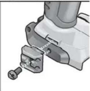
natural_image
Mechanical assembly diagram showing a tool interacting with a bracket (no text or symbols visible)تنبیه!

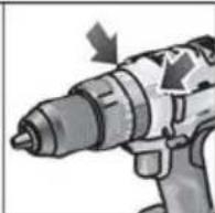
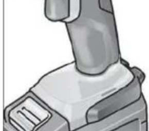
natural_image
Close-up of a mechanical lever component (no visible text or symbols)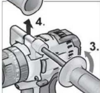
نظرة عامة



- i HINWEIS
- Demontieren
- Drehmomentvorwahl
- VORSICHT!
- Symbols used in this manual
- WARNING!
- CAUTION!
- NOTE
- Symbols on the power tool
- Important safety information
- Intended use
- Safety instructions for drills and drivers
- Additional safety instruction for percussion drill (PD ...)
- Safety instructions for handling batteries
- Charger
- Special safety instructions
- Noise and vibration
- i NOTE
- Overview
- Instructions for use
- Before initial operation
- Fitting/removing the auxiliary handle (PD/DD 2G 18.0-EC)
- Changeable drill chuck BF 18.0-EC
- Assemble
- Disassemble
- Inserting the tools
- Angle attachment WV 18.0-EC
- Bit holder attachment BV 18.0-EC
- Tool change
- Inserting/replacing the battery
- Battery state of charge
- Direction preselection
- Operating mode
- (PD 2G 18.0-EC only)
- Torque preselection
- Speed preselection
- Switching on the power tool
- Workplace lamp on/off switch
- Speed and torque preselector switch IW 1/2" 18.0-EC / ID 1/4" 18.0-EC
- Change speed/torque
- Change single impact mode to impact driver mode
- Working with the power tool
- Tips for a long battery service life
- Charging process
- Maintenance and care
- Cleaning
- Repairs
- Spare parts and accessories
- Transport
- CE conformity
- Exemption from liability
- Table des matières
- Mandrin de perçage interchangeable BF 18.0-EC
- Démontage
- Adaptateur porte-embout BV 18.0-EC
- PRUDENCE!
- i AVVERTENZA
- Mandrino intercambiabile BF 18.0-EC
- PRUDENZA!
- Smontaggio
- AVVERTENZA
- Portabrocas intercambiable BF 18.0-EC
- Desmontaje
- Adaptador portabrocas BV 18.0-EC
- ¡CUIDADO!
- i INDICAÇÃO
- Desmontar
- Demonteren
- Snelheidsselectie
- VOORZICHTIG!
- i BEMAERK
- Vekselpatron BF 18.0-EC
- ! FORSIGTIG!
- Afmontering
- Bitholderforsats BV 18.0-EC
- FORSIGTIG!
- Momentvalg
- BEMAERK
- Hastighedsforvalg
- i
- i HENVISNING
- Skiftechuck BF 18.0-EC
- FORSIKTIG!
- Demontering
- Bitsholderforsats BV 18.0-EC
- Dreiemomentforvalg
- Hastighetsforvalg
- Snabbchuck BF 18.0-EC
- VAR FÖRSIKTIG!
- Demontera
- i OHJE
- Irrotus
- OHJE
- Nopeuden esivalinta
- VARO!
- i YΠΟΔΕΙΞΗ
- Αφαίρεση
- Τρύπημα
- ΥΠΟΔΕΙΞΗ
- i BİLGİ
- Sökme
- Sökülmesi
- Tork ön seçimi
- DİKKAT!
- Hız ön seçimi
- i WSKAZÓWKA
- Wymienny uchwyt wiertarski BF 18.0-EC
- OSTROŻNIE!
- Demontaż
- WSKAZÓWKA
- i MEGJEGYZÉS
- Leszerelés
- Demontáž
- Předvolba rychlosti
- POZOR!
- i UPOZORNĚNÍ
- i UPOZORNENIE
- Nadstavec pre držiak hrotov BV 18.0-EC
- Vloženie nástrojov
- Predvoľba rýchlosti
- Nabíjačka
- i NAPOMENA
- Montaža/demontaža dodatne ručke (PD/DD 2G 18.0-EC)
- OPREZ!
- Demontiranje
- Umetanje alata
- Držač nastavka BV 18.0-EC
- Montiranje
- Zamjena alata
- Odabir brzine
- i OPOMBA
- Izmenljiva vrtalna glava BF 18.0-EC
- Demontaža
- Vpenjanje nastavkov
- Vpetje za nastavke BV 18.0-EC
- Menjava orodja IW
- Izbira vrtilnega momenta
- Izbira hitrosti
- OPOMBA
- i INDICATIE
- Demontarea
- Introducerea sculelor
- Cap aplicat cu suport de bituri BV 18.0-EC
- PRECAUTIE!
- Preselectarea vitezei
- i УКАЗАНИЕ
- Демонтиране
- Избор на скорост
- ВНИМАНИЕ!
- Снятие
- Выбор скорости
- Vahetatav padrun BF 18.0-EC
- ETTEVAATUST!
- Eemaldamine
- Otsakuhoidikumanus BV 18.0-EC
- Tööriistavahetus
- Kiiruse eelvalik
- i NURODYMAS
- Greito keitimo griebtuvas BF 18.0-EC
- ATSARGIA!!
- Išmontavimas
- Sukimo momento parinktis
- NURODYMAS
- Greičio parinktis
- Krovimo prietaisas
- i NORĀDE
- Demontāža
- Instrumenta
- UZMANĪBU!
- Ātruma izvēle
- i NORÃDE
- WV 18.0-ECtriangle ABC
Brand : Flex
Model : DD 2G 18.0-EC
Category : Drill