GE MH 18.0-EC - Sander Flex - Free user manual and instructions
Find the device manual for free GE MH 18.0-EC Flex in PDF.


User questions about GE MH 18.0-EC Flex
0 question about this device. Answer the ones you know or ask your own.
Ask a new question about this device
Download the instructions for your Sander in PDF format for free! Find your manual GE MH 18.0-EC - Flex and take your electronic device back in hand. On this page are published all the documents necessary for the use of your device. GE MH 18.0-EC by Flex.
USER MANUAL GE MH 18.0-EC Flex
natural_image
Illustration of a handheld electric vehicle charging station with two motors (no text or symbols)de Originalbetriebsanleitung 8
en Original operating instructions 17
fr Notice d'instructions d'origine 25
it Istruzioni per l'uso originali .... 34
es Instrucciones de funcionamiento originales ..... 43
pt Instruções de serviço originais ..... 52
nl Originele gebruiksaanwijzing 61
da Originale driftsvejledning 70
no Originale driftsanvisningen 78
sv Originalbruksanvisning 86
fi Alkuperäinen käyttöohjekirja 93
el Auθεντικές οδηγίες χειρισμού 101
tr Orijinal işletme kılavuzu 110
pI Instrukcja oryginalna 118
hu Eredeti üzemeltetési útmutató 128
cs Originální návod k obsluze 137
sk Originálny návod na obsluhu 145
hr Originalna uputa za rad 153
sl Izvirno navodilo za obratovanje 161
ro Instructiuni de functionare originale 169
bg Оригинално упътване за експлоатация ..... 177
ru Оригинальная инструкция по эксплуатации ..... 187
et Originaalkasutusjuhend 197
It Originali naudojimo instrukcija 205
Iv Lietošanas pamācības oriģināls 213
ar إرشادات التشفيل الأصلية 227
text_image
Technical diagram of a handheld electric shock absorber with numbered parts and close-ups of internal components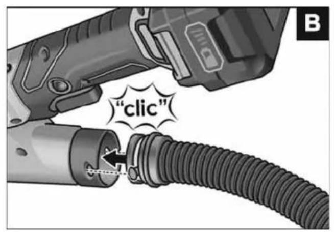
text_image
"click"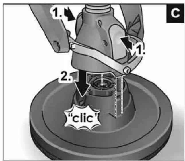
text_image
1. 2. 1. 2. "clic"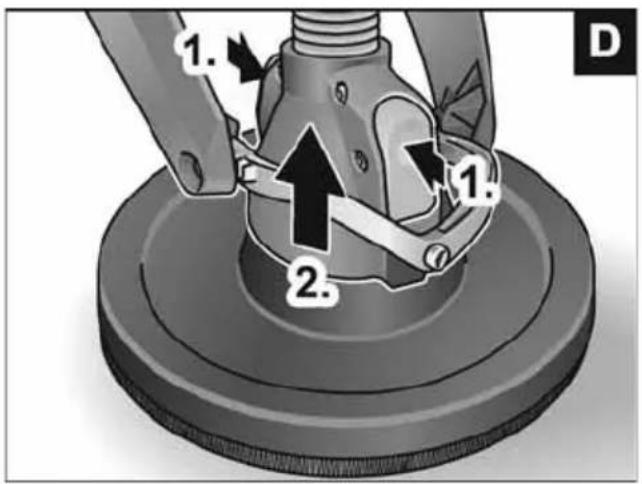
text_image
1. 2. 1. D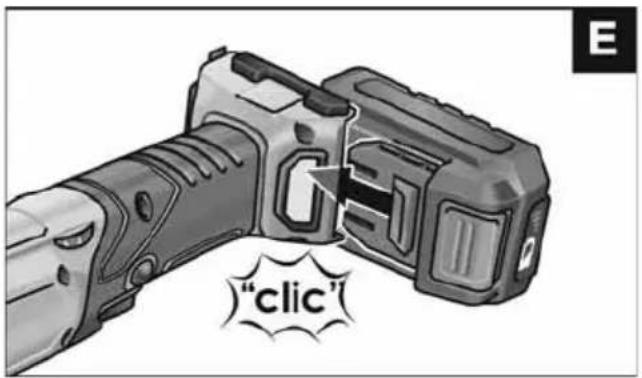
text_image
"clic"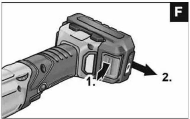
text_image
1. 2.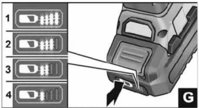
text_image
1 2 3 4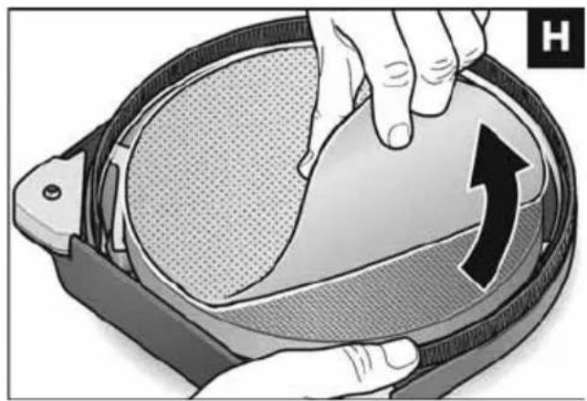
natural_image
Illustration of a hand pressing down on a circular object with an arrow indicating rotation (no text or symbols)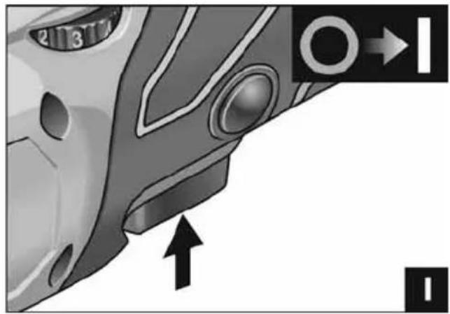
natural_image
Close-up of a car's front wheel and side door, showing no text or symbols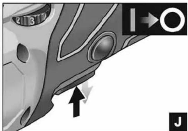
text_image
2 3 7 I→O J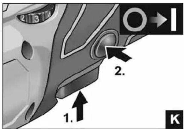
text_image
2 3 7 1. 2. K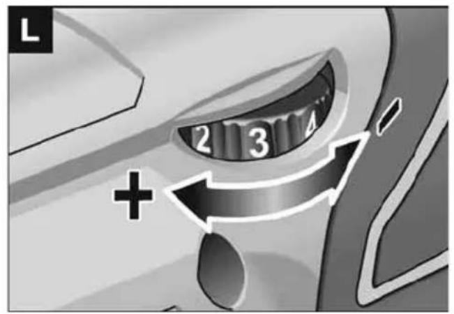
text_image
L 2 3 4 +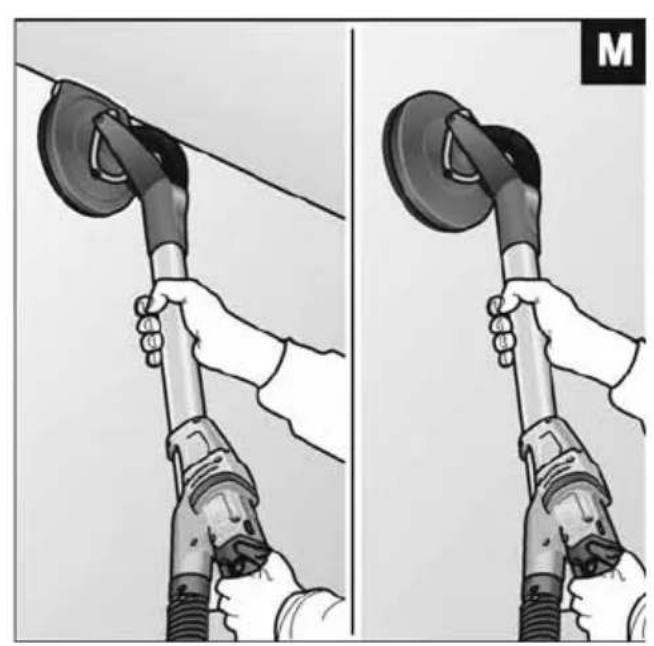
natural_image
Illustration of two hands using a power tool to lift a circular component, showing mechanical assembly (no text or symbols)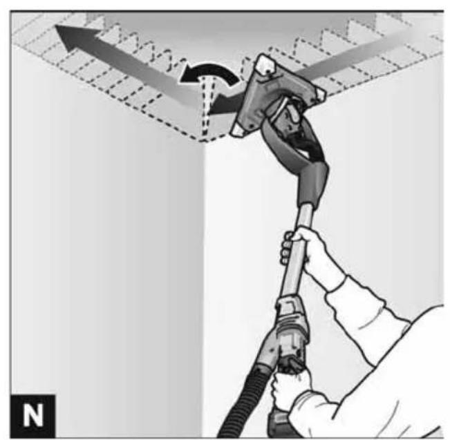
natural_image
Illustration of a hand using a fuel pump to lift a wall-mounted airfoil, with no text or symbols present.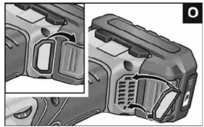
natural_image
Close-up of a mechanical component with internal channels and adjustment arrows (no text or symbols)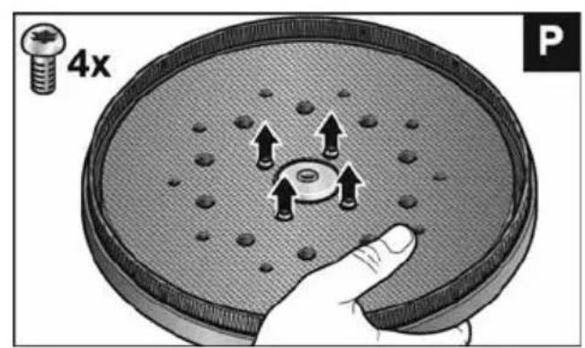
text_image
4x P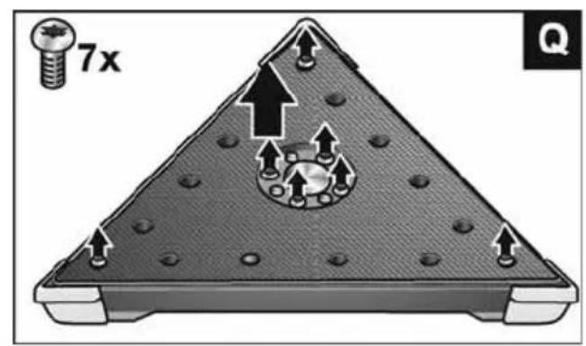
text_image
7x Q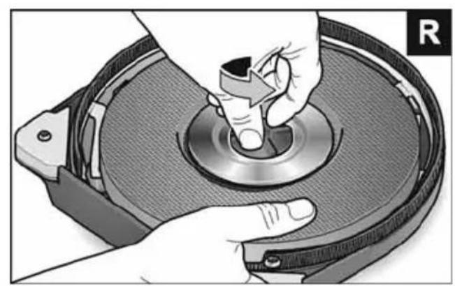
natural_image
Close-up of hands operating a CD or DVD disc with a knob, no visible text or symbols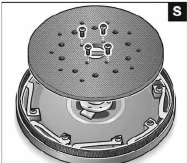
natural_image
Cross-sectional diagram of a mechanical device with internal components and mounting holes (no text or symbols)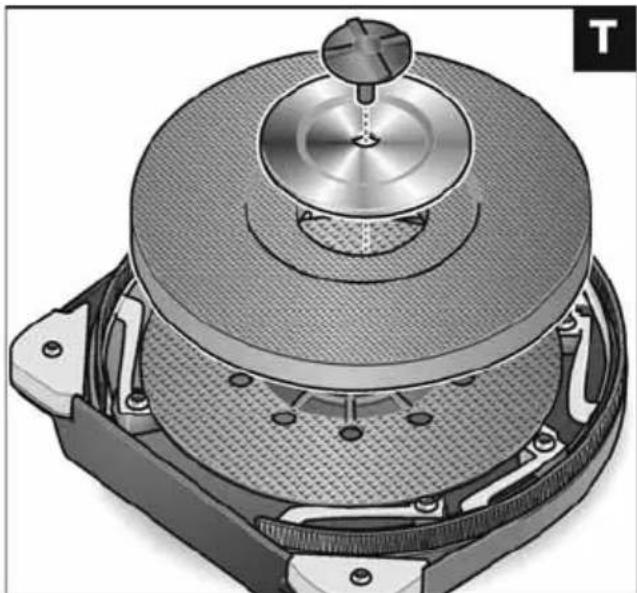
natural_image
Cross-sectional diagram of a mechanical device with a central rotating knob and textured base (no text or symbols)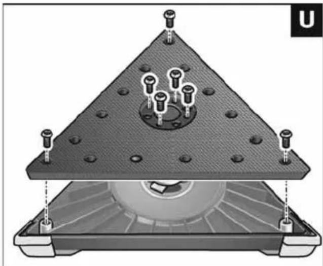
natural_image
Technical diagram of a mechanical assembly with a triangular base and internal components (no text or symbols)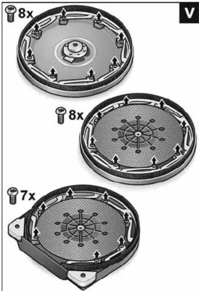
text_image
8x 8x 7x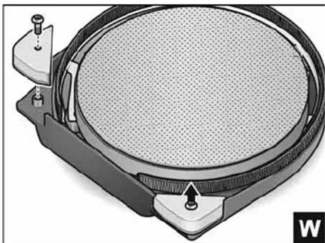
natural_image
Diagram of a circular mechanical component with internal mesh structure and two adjustment knobs (no text or symbols)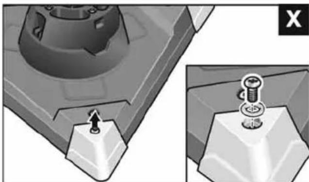
natural_image
Mechanical assembly diagram showing a component with a bolt and screw, alongside its cross-section view (no text or symbols)| GerätetypMachine typeType d'appareilTipo di apparecchioTipo de equipoTipo do aparelhoMachinetypeApparattypeApparattypeMaskintypKonetyyppiTúπος συσκευήςCihaz tipiTyp urządzeniaKészülék típusaTyp nářadíTyp náradiaTip aparataVrsta orodjaTipul aparatuluiTип на уредаТип прибораSeadmetüüp|rankio tipas|erīces modelis护راز الجهاز | WandschleiferWall sanderPonceuse muraleLevigatrice per paretiAmoladora para paredLixadeira de paredesWandschuurmachineVægsliberVeggsliperenVäggslipSeinähiomakoneΛειαντήρας τοίχουDuvar zımparasıSzlifierka do ścianFalcsiszolóBruska na stěnyBrúska na stenyZidną brusilicaŽirafaMaşină de şlefuit perețiШлифовъчен инструмент за стениШлифовальная машина для стенSeinalihvijaSienų šlifuoklisSienu sīpmašīnaجلاخة الحوانط | |||
| MH-O MH-R MH-T MH-X | ||||
| Schutzklasse III | ||||
| U V | 1 8 | |||
| I mm 1520 | ||||
| m „EPTA Procedure01/2003“ | kg 4,2 4,4 4,5 | |||
| SaugschlauchLänge x Durchmesser | mm 4000x32 | |||
| n 1/min 1150-1800 - | - | |||
| Leerlaufhubzahl 1/min | - 3950-6200 3200-5000 | |||
| ∅ | mm | 225 | 225 | |
| Kantenlänge | mm | - | 295 | - |
| Schleifhub mm | - 4 | |||
| L_pA | dB(A) | 78 | 79 | 78 |
| L_WA | dB(A) | 89 | 90 | 89 |
| K | dB | 3 | ||
| a_h , DS | m/s2 | < 2,5 | ||
| K | m/s2 | 1,5 | ||
Verwendete Symbole

WARNUNG!
Peter Lameli Technical Head
Klaus Peter Weinper Head of Quality Department (QD)
15.12.2020
Symbols used in this manual

WARNING!
Denotes impending danger.
Non-observance of this warning may result in death or extremely severe injuries.

CAUTION!
Denotes a possibly dangerous situation.
Non-observance of this warning may result in slight injury or damage to property.

NOTE
Denotes application tips and important information.
Symbols on the power tool

Before switching on the power tool, read the operating manual!

Wear goggles!

Disposal information for the old machine (see page 23)!
For your safety

WARNING!
Before using the power tool, please read and follow:
– these operating instructions,
- the "General safety instructions" on the handling of power tools in the enclosed booklet (leaflet-no.: 315.915),
– the currently valid site rules and the regulations for the prevention of accidents.
This power tool is state of the art and has been constructed in accordance with the acknowledged safety regulations. Nevertheless, when in use, the power tool may be a danger to life and limb of the user or a third party, or the power tool or other property may be damaged. The power tool may be operated only if it is
- as intended,
– in perfect working order.
Faults which impair safety must be repaired immediately.
Intended use
The wall sander GE MH 18.0-EC is designed
– for commercial use in industry and trade,
– for sanding walls and ceilings inside and outside,
– for sanding smoothed drywalls,
– for use with tools which FLEX offer for these power tools and which are authorised to run at a speed of at least 1900 r.p.m.
It is not permitted to use cutting-off wheels, roughing wheels, fan-like grinding wheels or wire brushes.
When using the wall sander GE MH 18.0-EC, connect a Class M dust extractor.
Safety instructions

WARNING!
Read all safety warnings and all instructions. Failure to follow the warnings and instructions may result in electric shock, fire and/or serious injuries. Save all warnings and instructions for future reference.
This power tool is intended to function as a sander. Read all safety warnings, instructions, illustrations and specifications provided with this power tool. Failure to follow all instructions listed below may result in electric shock, fire and/or serious injury.
■ Operations such as grinding, wire brushing, or for polishing and cut-off are not recommended to be performed with this power tool. Operations for which the power tool was not designed may create a hazard and cause personal injury.
■ Do not use accessories which are not specifically designed and recommended by the tool manufacturer. Just because the accessory can be attached to your power tool, it does not assure safe operation.
■ The rated speed of the accessory must be at least equal to the maximum speed marked on the power tool. Accessories running faster than their rated speed can break and fly apart.
■ The outside diameter and the thickness of your accessory must be within the capacity rating of your power tool. Incorrectly sized accessories cannot be adequately guarded or controlled.
Threaded mounting of accessories must match the grinder spindle thread. For accessories mounted by flanges, the arbour hole of the accessory must fit the locating diameter of the flange.
Accessories that do not match the mounting hardware of the power tool will run out of balance, vibrate excessively and may cause loss of control.
- Do not use a damaged accessory. Before each use inspect the accessory such as abrasive wheels for chips and cracks, backing pad for cracks, tear or excess wear, wire brush for loose or cracked wires. If power tool or accessory is dropped, inspect for damage or install an undamaged accessory. After inspecting and installing an accessory, position yourself and bystanders away from the plane of the rotating accessory and run the power tool at maximum no-load speed for one minute. Damaged accessories will normally break apart during this test time.
■ Wear personal protective equipment. Depending on application, use face shield, safety goggles or safety glasses. As appropriate, wear dust mask, hearing protectors, gloves and workshop apron capable of stopping small abrasive or workpiece fragments. The eye protection must be capable of stopping flying debris generated by various operations. The dust mask or respirator must be capable of filtrating particles generated by your operation. Prolonged exposure to high intensity noise may cause hearing loss.
- Keep bystanders a safe distance away from work area. Anyone entering the work area must wear personal protective equipment. Fragments of workpiece or of a broken accessory may fly away and cause injury beyond immediate area of operation.
■ Hold power tool by insulated gripping surfaces only, when performing an operation where the cutting accessory may contact hidden wiring or its own cord.
Cutting accessory contacting a "live" wire may make exposed metal parts of the power tool "live" and shock the operator.
■ Position the cord clear of the spinning accessory. If you lose control, the cord may be cut or snagged and your hand or arm may be pulled into the spinning accessory.
■ Never lay the power tool down until the accessory has come to a complete stop. The spinning accessory may grab the surface and pull the power tool out of your control.
■ Do not run the power tool while carrying it at your side. Accidental contact with the spinning accessory could snag your clothing, pulling the accessory into your body.
■ Regularly clean the power tool's air vents. The motor's fan will draw the dust inside the housing and excessive accumulation of powdered metal may cause electrical hazards.
■ Do not operate the power tool near flammable materials. Sparks could ignite these materials.
■ Do not use accessories that require liquid coolants. Using water or other liquid coolants may result in electrocution or shock.
Kickback and Related Warnings
Kickback is a sudden reaction to a pinched or snagged rotating wheel, backing pad, brush or any other accessory. Pinching or snagging causes rapid stalling of the rotating accessory which in turn causes the uncontrolled power tool to be forced in the direction opposite of the accessory's rotation at the point of the binding.
For example, if an abrasive wheel is snagged or pinched by the workpiece, the edge of the wheel that is entering into the pinch point can dig into the surface of the material causing the wheel to climb out or kick out. The wheel may either jump toward or away from the operator, depending on direction of the wheel's movement at the point of pinching. Abrasive wheels may also break under these conditions.
Kickback is the result of power tool misuse and/or incorrect operating procedures or conditions and can be avoided by taking proper precautions as given below.
- Maintain a firm grip on the power tool and position your body and arm to allow you to resist kickback forces. Always use auxiliary handle, if provided, for maximum control over kickback or torque reaction during start-up. The operator can control torque reactions or kickback forces, if proper precautions are taken.
■ Never place your hand near the rotating accessory. Accessory may kickback over your hand. - Do not position your body in the area where power tool will move if kickback occurs. Kickback will propel the tool in direction opposite to the wheel's movement at the point of snagging.
■ Use special care when working corners, sharp edges etc. Avoid bouncing and snagging the accessory. Corners, sharp edges or bouncing have a tendency to snag the rotating accessory and cause loss of control or kick-back.
■ Do not attach a saw chain woodcarving blade or toothed saw blade. Such blades create frequent kickback and loss of control.
Special safety instructions for sanding:
■ Do not use excessively oversized sanding disc paper. Follow manufacturers recommendations, when selecting sanding paper. Larger sanding paper extending beyond the sanding pad presents a laceration hazard and may cause snagging, tearing of the disc or kickback.
Additional safety instructions
■ Use only extension cables permitted for outdoor use.
■ It is not recommended to sand lead paint. Lead paint should be removed by a specialist only.
If plaster board or plaster is sanded, this may cause static electricity to build up on the tool. To ensure your safety, the wall sander is earthed. Remove dust with an earthed dust extractor only.
■ Do not work on materials which release hazardous substances (e.g. asbestos). Take precautions if hazardous, combustible or explosive dust is likely to occur. Wear protective dust mask. Use dust extraction system.

Damage to property!
The mains voltage and the voltage specifications on the rating plate must correspond.
Noise and vibration

NOTE
Values for the A-weighted sound pressure level and for the total vibration values can be found in the "Instructions for use" table. The noise and vibration values have been determined in accordance with EN 60745.

CAUTION!
The indicated measurements refer to new power tools. Daily use causes the noise and vibration values to change.

NOTE
The vibration emission level given in this information sheet has been measured in accordance with a standardised test given in EN 60745 and may be used to compare one tool with another. It may be used for a preliminary assessment of exposure. The declared vibration emission level represents the main applications of the tool. However if the tool is used for different applications, with different accessories or poorly maintained, the vibration emission may differ. This may significantly increase the exposure level over the total working period. However if the tool is used for different applications, with different accessories or poorly maintained, the vibration emission may differ. This may significantly decrease the exposure level over the total working
period. Identify additional safety measures to protect the operator from the effects of vibration such as: maintain the tool and the accessories, keep the hands warm, organisation of work patterns.

CAUTION!
Wear ear protection at a sound pressure above 85 dB(A).
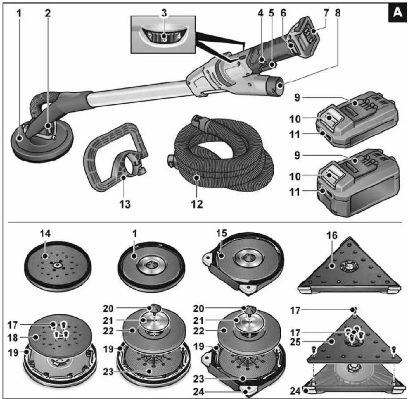
Overview (Figure A)
1 Sanding head
with closed brush ring
2 Gimbal bearings
3 Dial for preselecting the speed
4 Locking button
5 Switch
6 Filter cover
7 Slot for battery
8 32 mm connection
9 Flex Li-ion battery
10 Release button for battery
11 State of charge indicator
12 Suction hose
13 Bail handle (optional)
14 Orbital sander head
15 Sanding head
with open brush ring for sanding edges
16 Delta sander head
17 Fastening screws
18 Orbital Velcro plate
19 Brush ring
20 Screw
21 Retaining washer
22 Velcro pad
23 Backing pad
24 Replaceable protective corners
25 Delta Velcro plate
Instructions for use
Before switching on the power tool
Unpack power tool and accessories and check that no parts are missing or damaged.

NOTE
The batteries are not fully charged on delivery. Prior to initial operation, charge the batteries fully. Refer to the charger operating manual.
Connecting the extractor (Figure B)
■ Connect extraction hose to the 32 mm connector.

NOTE
The connection piece of the GE MH 18.0-EC is a new development. If electric power tools are used with conventional connection pieces together with the extraction hose of the GE MH 18.0-EC, an adapter from the FLEX accessories programme can be used.
Attaching/changing the sanding head

CAUTION!
Remove the battery before carrying out any work on the power tool.
To attach (Figure C):
■ Press the two locks on the tool change head (1.).
■ Put the tool change head on the sanding head (2.).
■ Check that the locking mechanisms have returned to the home position.
To change (Figure D):
■ Press the two locks on the tool change head (1.) and remove sanding head (2.).

NOTE
The delta sander head and orbital sander head are attached/changed in the same way.
Inserting/replacing the battery (Figure E-F)
■ Press the charged battery into the power tool until it clicks into place.
■ To remove, press the release button (1.) and pull out the battery (2.).

CAUTION!
When the device is not in use, protect the battery contacts. Loose metal parts may short-circuit the contacts; explosion and fire hazard!
Battery state of charge
■ Press the button to check the state of charge at the state of charge indicator LEDs.
The indicator goes out after 5 seconds. If one of the LEDs flashes, the battery must be recharged. If none of the LEDs light up after the button is pressed, the battery is faulty and must be replaced.
Using a dust extraction system

CAUTION!
- When using the wall sander, connect a Class M dust extractor.
- If a dust bag is used which is not authorised for use with dry construction dust, the amount of dust particles in the air may increase at the work place. Over a prolonged period high concentrations of dust in the air may damage the human respiratory system.
■ Insert the special dust bag for dry construction dust into your dust extractor according to the instructions supplied with the dust extractor.
■ Connect extraction hose to the dust extraction system. Follow the operating instructions for the dust extraction system! Check the attachment! If required, use an appropriate adapter.

NOTE
If your dust extractor requires a special connector, the clip-on connection can be removed and a matching adapter selected from the FLEX accessories range.
Attaching and changing the sanding tools (Figure H)

CAUTION!
Remove the battery before carrying out any work on the power tool.
■ Remove worn sanding tool from the Velcro pad.
■ Place the sanding sheet in the centre of the Velcro pad and press on.
■ Conduct a test run to check that the sanding tool is clamped in the centre.

CAUTION!
Never use the Velcro pad as a sanding tool. Never use the wall sander without the sanding sheet, otherwise the work surface will be seriously damaged!
Switch on and off (Figure I-K)
Brief operation without engaged switch rocker (Figure I)
■ Press and hold down the switch.
■ To switch off, release the switch.
Continuous operation with engaged switch rocker (Figure I-K)
■ Press and hold down the switch (1.).
■ To lock into position, hold down the locking button (2.) and release the switch.
■ To switch off, briefly press and release the switch.
Preselecting the speed (Figure L)
■ To set the operating speed, move the dial to the required value.
■ Gently press the switch to accelerate the power tool up to the preselected speed.
Using bar-type handle (optional)
To stabilise the working position, it is possible to mount a bar-type handle on the handle tube. The mounting position can be determined individually.
Using adapter for suction hose (optional)
The adapter can be used for connecting suction hoses of different dimensions.
Working with the power tool (Figure M)

CAUTION!
Hold the electric power tool with both hands! When working, always have one hand on the handle – even when working with attached extension. Keep your hands away from the sanding head.
Otherwise, your hand could become caught, as the sanding head swivels in different directions.
- Attach sanding tool.
-
Connect dust extraction system.
-
Insert mains plug.
- Set required speed.
- Switch on dust extraction system.
- Hold the wall sander with both hands. This provides the best possible combination of range and leverage for the application.
- Switch on the device.
- Press the wall sander gently against the work surface (the pressure should be just enough to ensure that the sanding head is flush with the work surface).
- Increase the pressure to bring the sanding sheet into contact with the work surface. In doing so, swing the sander in overlapping movements to smooth the surface to the required fineness.

CAUTION!
The rotating parts of the sanding head must not come into contact with sharp projecting objects (e.g. nails, screws, junction boxes). The Velcro pad may be damaged if it comes into contact with projecting objects. The Velcro pad can be replaced if it is damaged or severely abraded (see section entitled “Maintenance and care”).
Operating instructions
Brush ring
A brush-type ring surrounds the sanding head. This ring has two functions:
- As the ring projects above the surface of the sanding plate, it is the ring which comes into contact with the work surface first. As a result, the sanding head is brought parallel to the work surface before the sanding tool comes into contact with the work surface. This avoids a sickle-shaped depression caused by the edge of the sanding disc.
- The ring also retains the dust until it is extracted by the dust extractor. If the brush ring is damaged or shows excessive wear, it should be replaced (see section entitled “Maintenance and care”). Replacement brush rings are available from any FLEX customer service centre.
Sanding in dry construction
The wall sander features a unique swivel head. As this head can swivel in different directions, the sanding head can be adjusted to the work surface.
As a result, the user can sand the upper, middle and lower wall areas or ceiling profiles without having to change his position.
When working, apply only as much pressure as is required to keep the sanding plate in contact with the work surface. Excessive pressure may result in a disagreeable spiral pattern of scratches and an uneven work surface.
Move the sander constantly while the sanding plate is in contact with the work surface. In doing so, ensure that you move the sander evenly and over a wide area.
If you stop the sander on the work surface or move the sander unevenly, this may result in a disagreeable spiral pattern of scratches and an uneven work surface.
i NOTE
In the event of overload or overheating in non-stop operation, the power tool will switch off.
To continue working, switch the power tool off and back on again.
Triangular sanding head (Figure N)
The triangular sanding head does not rotate, but vibrates.
As the triangular sanding head can revolve on bearings, it can sand right into the corners of the wall/ceiling.
Maintenance and care
WARNING!
Remove the battery before carrying out any work on the power tool.
Cleaning (Figure O)
WARNING!
Do not use water or liquid detergents.
■ Clean the power tool and grille in front of the vent slots regularly. Frequency of cleaning is dependent on the material and duration of use.
■ Regularly blow out the housing interior and motor with dry compressed air.
■ Regularly clean the filter cover. Remove filter cover and blow it out with dry compressed air.
Replacing Velcro or backing pad (Figure P-U)
■ Take hold of the sanding plate together with the sanding head to prevent the sanding plate from turning.
■ Turn the bolts in anti-clockwise direction and remove.
■ The Velcro plates can be detached/removed.
- Replace parts.
■ Assemble sanding head in reverse sequence.
Replacing the brush ring (Figure V)
■ Remove the sanding head (see section "Replacing Velcro or backing pad (Figure P-U)").
■ Loosen the retaining screws.
■ Take the ring out of the housing.
■ Insert a new brush ring into the housing and screw in the retaining screws.
■ Assemble sanding head in reverse sequence.
Replacing the protective corners (Figure W-X)
■ Remove protective corners to be replaced.
■ Attach new protective corners.
In the corners reduce the contact pressure, otherwise there will be excessive load on the tips of the triangular sanding disc. Heavily worn corners of the triangular sanding head can easily be replaced.
Repairs
Repairs may be carried out by an authorised customer service centre only.
i NOTE
During the warranty period do not loosen the screws on the housing.
Non-compliance will deem the guarantee obligations of the manufacturer null and void.
Spare parts and accessories
Other accessories, in particular insertion tools, can be found in the manufacturer's catalogues.
Exploded drawings and spare-part lists can be found on our homepage:
www.flex-tools.com
Disposal information
WARNING!
Render redundant power tools unusable:
- mains operated power tool by removing the power cord,
- battery operated power tool by removing the battery.
EU countries only Do not throw electric power tools into the household waste!
In accordance with the European Directive 2012/19/EU on Waste Electrical and Electronic Equipment and transposition into national law used electric power tools must be collected separately and recycled in an environmentally friendly manner.
Raw material recovery instead of waste disposal.
Device, accessories and packaging should be recycled in an environmentally friendly manner. Plastic parts are identified for recycling according to material type.
WARNING!
Do not throw batteries into the household waste, fire or water. Do not open used batteries.
EU countries only:
In accordance with Directive 2006/66/EC defective or used batteries must be recycled
i NOTE
Please ask your dealer about disposal options!
C ∈ Declaration of Conformity
We declare under our sole responsibility that the product described under "Instructions for use" conforms to the following standards or normative documents:
EN 60745 in accordance with the regulations of the directives 2014/30/EU, 2006/42/EC, and 2011/65/EU.
Responsible for technical documents: FLEX-Elektrowerkzeuge GmbH, R & D Bahnhofstrasse 15, D-71711 Steinheim/Murr
text_image
i.v. P.Caudé B.S.A. -1Peter Lameli Technical Head
Klaus Peter Weinper Head of Quality Department (QD)
15.12.2020
Declaration of Conformity
We as the manufacturer: FLEX Elektrowerkzeuge GmbH,
Business address: Bahnhofstr. 15, 71711 Steinheim, Germany
declare under our sole responsibility, that the product(s) described under „Technical specifications“ fulfills all the relevant provisions of The Supply of Machinery (Safety) Regulations S.I. 2008/1597 and also fulfills all the relevant provisions of the following UK Regulations:
Electromagnetic Compatibility Regulations S.I. 2016/1091, The Restriction of the Use of Certain Hazardous Substances in Electrical and Electronic Equipment Regulations S.I. 2012/3032 and are manufactured in accordance with the following designated Standards: BS EN 60745-1:2010,
BS EN 60745-2-3:2011, BS EN 55014-1:2017, BS EN 55014-2:2015
Place of declaration: Steinheim, Germany.
Responsible person: Peter Lameli, Technical Director – FLEX-Elektrowerkzeuge GmbH
Contact details for Great Britain:
FLEX Power Tools Limited, Unit 8 Anglo Office Park, Lincoln Road, HP 12, 3RH Buckinghamshire, United Kingdom
text_image
i.v. P.Caudi B.S.A.D.Peter Lameli Technical Head
Klaus Peter Weinper Head of Quality Department (QD)
19.05.2021
Exemption from liability
The manufacturer and his representative are not liable for any damage and lost profit due to interruption in business caused by the product or by an unusable product. The manufacturer and his representative are not liable for any damage which was caused by improper use of the power tool or by use of the power tool with products from other manufacturers.
Symboles utilisés

AVERTISSEMENT!
Peter Lameli
Technical Head
text_image
Bolts Q - 1Klaus Peter Weinper Head of Quality Department (QD)
15.12.2020
Peter Lameli Technical Head
Klaus Peter Weinper Head of Quality Department (QD)
15.12.2020
Para sujetar (Figura C):
Peter Lameli Technical Head
Klaus Peter Weinper Head of Quality Department (QD)
15.12.2020
EN 60745 de acordo com as determinações das directivas 2014/30/UE, 2006/42/CE, 2011/65/UE.
Peter Lameli
Technical Head
text_image
B H Q -25Klaus Peter Weinper
Head of Quality
Department (QD)
15.12.2020
Fastgørelse (Figur C):
Peter Lameli Technical Head
Klaus Peter Weinper Head of Quality Department (QD)
15-12-2020
For festing (Figur C):
For skifting (Figur D):
Peter Lameli Technical Head
text_image
Bolters -1Klaus Peter Weinper Head of Quality Department (QD)
15.12.2020
För montering (Figur C):
Peter Lameli Technical Head
Klaus Peter Weinper Head of Quality Department (QD)
2020-12-15
text_image
Bilcois -1Peter Lameli Technical Head
Klaus Peter Weinper
Head of Quality
Department (QD)
15.12.2020
Peter Lameli Technical Head
text_image
B H O -1Klaus Peter Weinper Head of Quality Department (QD)
15/12/2020

Peter Lameli
Technical Head
text_image
B H Q -1Klaus Peter Weinper
Head of Quality
Department (QD)
15.12.2020
Peter Lameli Technical Head
Klaus Peter Weinper Head of Quality Department (QD)
15.12.2020
Peter Lameli Technical Head
Klaus Peter Weinper Head of Quality Department (QD)
-
- 15
Peter Lameli Technical Head
Klaus Peter Weinper Head of Quality Department (QD)
15.12.2020
Peter Lameli
Technical Head
Klaus Peter Weinper
Head of Quality
Department (QD)
15.12.2020
Peter Lameli Technical Head
Klaus Peter Weinper Head of Quality Department (QD)
15.12.2020
Za pritrditev (Slika C):
■ Pritisnite obe zapori na menjalni glavi orodja (1.).
■ Menjalno glavo orodja nataknite na brusilno glavo (2.).
■ Preverite, ali sta se zapori vrnili v izhodiščni položaj.

Peter Lameli
Technical Head
text_image
B. B. B. B.Klaus Peter Weinper Head of Quality Department (QD)
15.12.2020
Directivei 2014/30/UE, 2006/42/CE, 2011/65/UE.
Peter Lameli
Technical Head
text_image
B W Q -1Klaus Peter Weinper Head of Quality Department (QD)
15.12.2020
Peter Lameli Technical Head
Klaus Peter Weinper Head of Quality Department (QD)
15.12.2020
Peter Lameli Technical Head
Klaus Peter Weinper Head of Quality Department (QD)
15.12.2020
Peter Lameli Technical Head
Klaus Peter Weinper Head of Quality Department (QD)
15.12.2020
text_image
B K L O - 1Peter Lameli Technical Head
Klaus Peter Weinper Head of Quality Department (QD)
2020-12-15
text_image
Handwritten signature or scribble with partial text and a curved line, likely from a document or form.Peter Lameli Technical Head
Klaus Peter Weinper Head of Quality Department (QD)
15.12.2020
Peter Lameli Technical Head
text_image
Bolts Q - 1Klaus Peter Weinper Head of Quality Department (QD)
2020/12/15