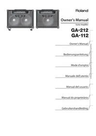
GA-212 - Guitar amp ROLAND - Free user manual and instructions
Find the device manual for free GA-212 ROLAND in PDF.


| Product type | Guitar amplifier |
| Brand | Roland |
| Model | GA-212 |
| Rated output power | 200 W |
| Speaker | 2 x 30 cm (12 inches) custom |
| Number of channels | 4 (CH1-CH4) + MANUAL mode |
| Technologies | PROGRESSIVE AMP, COSM |
| Controls | Drive, Volume, Bass, Middle, Treble, Presence, Reverb; BOOST, MID BOOST, VOICE buttons; A/B effect loops |
| Effect loops | 2 (EFX LOOP A and B) with SERIES/PARALLEL switch and level (+4 dBu/-10 dBu) |
| Reverb | Built-in, specially designed |
| Inputs | INPUT HIGH/LOW (6.35 mm jack), MAIN IN A/B (6.35 mm jack) |
| Outputs | LINE OUT (6.35 mm stereo jack), THRU/TUNER OUT (6.35 mm jack) |
| Control connectors | FOOT CONTROL/LINK IN (6.35 mm stereo jack), LINK OUT |
| AUTO OFF function | Yes, can be disabled (4 hours) |
| Optional foot controller | GA FOOT CONTROLLER (GA-FC) |
| Compatible expression pedals | Roland EV-5, BOSS FV-500L, FV-500H |
| Dimensions (W x D x H) | 715 x 337 x 560 mm |
| Weight | 32 kg |
| Power consumption | 75 W |
| Power supply | Mains via included power cord (grounding required) |
| Maintenance and cleaning | Dry, soft cloth; do not use solvents; wipe any liquid immediately |
| Safety | Do not open or modify; use only included cord; unplug during storms; avoid moisture |
| Spare parts and repairability | Contact an authorized Roland service center; speaker not user-replaceable |
| General information | Manual available in multiple languages; automatic standby; stackability (single unit only) |
Frequently Asked Questions - GA-212 ROLAND
User questions about GA-212 ROLAND
0 question about this device. Answer the ones you know or ask your own.
Ask a new question about this device
Download the instructions for your Guitar amp in PDF format for free! Find your manual GA-212 - ROLAND and take your electronic device back in hand. On this page are published all the documents necessary for the use of your device. GA-212 by ROLAND.
USER MANUAL GA-212 ROLAND
natural_image
Front view of a portable electronic audio amplifier with hexagonal grille and control knobs (no visible text or symbols)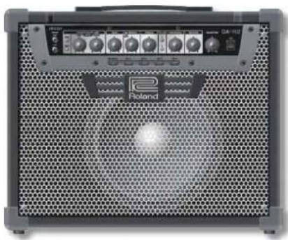
natural_image
Front view of a black electronic audio amplifier with hexagonal grille and control knobs (no visible text or symbols)Roland
Owner's Manual
Guitar Amplifier
GA-212 GA-112
Owner's Manual
Bedienungsanleitung
Mode d'emploi
Manuale dell'utente
Manual del usuario
WARNING: To reduce the risk of fire or electric shock, do not expose this apparatus to rain or moisture.



ATTENTION: RISQUE DE CHOC ELECTRIQUE NE PAS OUVRIR
CAUTION: TO REDUCE THE RISK OF ELECTRIC SHOCK, DO NOT REMOVE COVER (OR BACK).
NO USER-SERVICEABLE PARTS INSIDE.
REFER SERVICING TO QUALIFIED SERVICE PERSONNEL.

The lightning flash with arrowhead symbol, within an equilateral triangle, is intended to alert the user to the presence of uninsulated “dangerous voltage” within the product’s enclosure that may be of sufficient magnitude to constitute a risk of electric shock to persons.

The exclamation point within an equilateral triangle is intended to alert the user to the presence of important operating and maintenance (servicing) instructions in the literature accompanying the product.
INSTRUCTIONS PERTAINING TO A RISK OF FIRE, ELECTRIC SHOCK, OR INJURY TO PERSONS.
IMPORTANT SAFETY INSTRUCTIONS SAVE THESE INSTRUCTIONS
WARNING - When using electric products, basic precautions should always be followed, including the following:
- Read these instructions.
- Keep these instructions.
- Heed all warnings.
- Follow all instructions.
- Do not use this apparatus near water.
- Clean only with a dry cloth.
- Do not block any of the ventilation openings. Install in accordance with the manufacturers instructions.
-
Do not install near any heat sources such as radiators, heat registers, stoves, or other apparatus (including amplifiers) that produce heat.
-
Do not defeat the safety purpose of the polarized or grounding-type plug. A polarized plug has two blades with one wider than the other. A grounding type plug has two blades and a third grounding prong. The wide blade or the third prong are provided for your safety. If the provided plug does not fit into your outlet, consult an electrician for replacement of the obsolete outlet.
-
Protect the power cord from being walked on or pinched particularly at plugs, convenience receptacles, and the point where they exit from the apparatus.
-
Only use attachments/accessories specified by the manufacturer.
-
Unplug this apparatus during lightning storms or when unused for long periods of time.
-
Refer all servicing to qualified service personnel. Servicing is required when the apparatus has been damaged in any way, such as power-supply cord or plug is damaged, liquid has been spilled or objects have fallen into the apparatus, the apparatus has been exposed to rain or moisture, does not operate normally, or has been dropped.
For the U.K.
WARNING: THIS APPARATUS MUST BE EARTHED
IMPORTANT: THE WIRES IN THIS MAINS LEAD ARE COLOURED IN ACCORDANCE WITH THE FOLLOWING CODE. GREEN-AND-YELLOW: EARTH, BLUE: NEUTRAL, BROWN: LIVE
As the colours of the wires in the mains lead of this apparatus may not correspond with the coloured markings identifying the terminals in your plug, proceed as follows:
The wire which is coloured GREEN-AND-YELLOW must be connected to the terminal in the plug which is marked by the letter E or by the safety earth symbol ⊕ or coloured GREEN or GREEN-AND-YELLOW.
The wire which is coloured BLUE must be connected to the terminal which is marked with the letter N or coloured BLACK.
The wire which is coloured BROWN must be connected to the terminal which is marked with the letter L or coloured RED.
natural_image
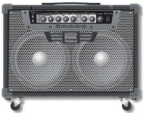
Front view of a Poland audio amplifier with visible grille and buttons (no text or symbols on body)GA-212
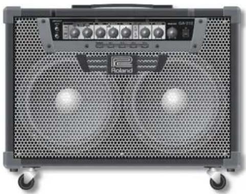
A guitar amp with 200 W output and two custom 30 cm (12-inch) speakers.
natural_image
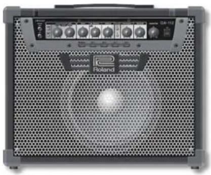
Front view of a Roland audio amplifier with hexagonal grille and control knobs (no visible text or symbols)GA-112
A guitar amp with 100 W output and one custom 30 cm (12-inch) speaker.
Owner's Manual
Guitar Amplifier
GA-212 GA-112
Roland's PROGRESSIVE AMP technology gives a broader and richer guitar sound
This newly developed PROGRESSIVE AMP with COSM technology offers an original drive control, enabling continuous and smooth changes, not only for gain, but between the amp's characteristics as well. This feature allows a variety of rich sounds and is ideal for many different types of performance, from a good clear clean sound to a sticky crunch sound, and through to high-gain super extreme, and also allows comfortable playing with distortion.
Intuitive operation
The GA-212/GA-112 are equipped with four channels and you can set different tones for each channel. Each knob has an LED pointer that indicates the current setting. The LED pointer allows at-a-glance tone checking and quickly indicates any change of channel. The channel settings are automatically saved after every operation. The exclusive foot controller gives easy foot control of the GA (p. 8).
Equipped with simple operation of basic functions and expandability
In addition to 3-band EQ, presence and mid boost allow versatile sound creation. Exclusively-designed reverb gives great spatial effects. The unit is equipped with two independent effect loops and can be set for each channel. The unit has the basic functions needed for both live performance and recording. Link connection can also be easily made, allowing you to enjoy a performance with a more powerful sound.
What is COSM?
Composite Object Sound Modeling (COSM) is Roland's innovative and powerful sound modeling technology. COSM analyzes the many factors that make up the original sound, such as the electrical and physical characteristics of the original, and then produces a digital model that can reproduce the same sound.

AUTO OFF function
- The unit has an energy-saving AUTO OFF function; the unit is automatically turned off approximately 4 hours after last use.
- When shipped from the factory, the unit comes with the AUTO OFF function turned ON.
• To override the energy-saving setting, set the [AUTO OFF] switch to OFF as described on p. 6.
About The Exclusive Foot Controller
- The exclusive foot controller (GA FOOT CONTROLLER) is an available option.
Copyright © 2012 ROLAND CORPORATION
All rights reserved. No part of this publication may be reproduced in any form without the written permission of ROLAND CORPORATION.
"What type of stage amplifier do guitarists really want?" After much intensive research and development, GA is Roland's answer.
GA is an amp with easy intuitive operation and with a sound that resonates with the guitarist's inspiration.
By focusing on these key points, a "live amp" was born with a sound character that satisfies guitarists, simple operation and all the functions required for a great live performance.
In our search for a sound that moves the performer's heart, we experimented endlessly to get it just right. Our efforts have borne fruit and we believe Roland's unique amp delivers sound quality beyond tube and solid state amps.
It was also essential to ensure that operating the unit was simple and intuitive. All guitarists desire "to only concentrate on artistic performance, without being diverted by technical control." This amp is designed with simple and intuitive operation and is ideal for all guitarists.
GA is the next-generation stage guitar amp, born from Roland's years of technological experience and know-how.
Before using this unit, carefully read the sections entitled: "IMPORTANT SAFETY INSTRUCTIONS" (inside front cover), "USING THE UNIT SAFELY" (p. 2), and "IMPORTANT NOTES" (p. 3). These sections provide important information concerning the proper operation of the unit. Additionally, in order to feel assured that you have gained a good grasp of every feature provided by your new unit, Owner's Manual should be read in its entirety. The manual should be saved and kept on hand as a convenient reference.
INSTRUCTIONS FOR THE PREVENTION OF FIRE, ELECTRIC SHOCK, OR INJURY TO PERSONS
About ⚠ WARNING and ⚠ CAUTION Notices
| WARNING | Used for instructions intended to alert the user to the risk of death or severe injury should the unit be used improperly. |
| CAUTION | Used for instructions intended to alert the user to the risk of injury or material damage should the unit be used improperly.* Material damage refers to damage or other adverse effects caused with respect to the home and all its furnishings, as well to domestic animals or pets. |
About the Symbols
| The △symbol alerts the user to important instructions or warnings. The specific meaning of the symbol is determined by the design contained within the triangle. In the case of the symbol at left, it is used for general cautions, warnings, or alerts to danger. | |
| The ◎symbol alerts the user to items that must never be carried out (are forbidden). The specific thing that must not be done is indicated by the design contained within the circle. In the case of the symbol at left, it means that the unit must never be disassembled. | |
| The ●symbol alerts the user to things that must be carried out. The specific thing that must be done is indicated by the design contained within the circle. In the case of the symbol at left, it means that the power-cord plug must be unplugged from the outlet. |
ALWAYS OBSERVE THE FOLLOWING
! WARNING
Make sure that the power cord is grounded
Connect mains plug of this model to a mains socket outlet with a protective earthing connection.

Do not disassemble or modify by yourself
Do not open or perform any internal modifications on the unit.

Do not repair or replace parts by yourself
Do not attempt to repair the unit, or replace parts within it (except when this manual provides specific instructions directing you to do so). Refer all servicing to your retailer, the nearest Roland Service Center, or an authorized Roland distributor, as listed on the "Information" page.

Do not use or store in the following types of locations
- Subject to temperature extremes (e.g., direct sunlight in an enclosed vehicle, near a heating duct, on top of heat-generating equipment); or are
- Damp (e.g., baths, washrooms, on wet floors); or are
- Exposed to steam or smoke; or are
- Subject to salt exposure; or are
- Humid; or are
- Exposed to rain; or are
• Dusty or sandy; or are - Subject to high levels of vibration and shakiness.


Do not place in an unstable location
Make sure you always have the unit placed so it is level and sure to remain stable. Never place it on stands that could wobble, or on inclined surfaces.

Connect the power cord to an outlet of the correct
voltage
The unit should be connected to a power supply only of the type described as marked on the rear side of unit.

WARNING
Use only the included power cord
Use only the attached power-supply cord. Also, the included power cord must not be used with any other device.

Do not bend the power cord or place heavy objects
on it
Do not excessively twist or bend the power cord, nor place heavy objects on it. Doing so can damage the cord, producing severed elements and short circuits. Damaged cords are fire and shock hazards!

Avoid extended use at high volume
This unit, either alone or in combination with an amplifier or speakers, may be capable of producing sound levels that could cause permanent hearing loss. Do not operate for a long period of time at a high volume level, or at a level that is uncomfortable. If you experience any hearing loss or ringing in the ears, you should immediately stop using the unit, and consult an audiologist.

Don't allow foreign objects or liquids to enter unit;
never place containers with liquid on unit
Do not place containers containing liquid on this product. Never allow foreign objects (e.g., flammable objects, coins, wires) or liquids (e.g., water or juice) to enter this product. Doing so may cause short circuits, faulty operation, or other malfunctions.


! WARNING
Turn off the unit if an abnormality or malfunction occurs
Immediately turn the unit off, remove the power cord from the outlet, and request servicing by your retailer, the nearest Roland Service Center, or an authorized Roland distributor, as listed on the "Information" page when:

- The power-supply cord or the plug has been damaged; or
• If smoke or unusual odor occurs; or - Objects have fallen into, or liquid has been spilled onto the unit; or
• The unit has been exposed to rain (or otherwise has become wet); or - The unit does not appear to operate normally or exhibits a marked change in performance.
Adults must provide supervision in places where children are present
When using the unit in locations where children are present, be careful so no mishandling of the unit can take place. An adult should always be on hand to provide supervision and guidance.

Do not drop or subject to strong impact
Protect the unit from strong impact. (Do not drop it!)

Do not share an outlet with an unreasonable number of other devices
Do not force the unit's power-supply cord to share an outlet with an unreasonable number of other devices. Be especially careful when using extension cords—the total power used by all devices you have connected to the extension cord's outlet must never exceed the power rating (watts/amperes) for the extension cord. Excessive loads can cause the insulation on the cord to heat up and eventually melt through.

Do not use overseas
Before using the unit in a foreign country, consult with your retailer, the nearest Roland Service Center, or an authorized Roland distributor, as listed on the "Information" page.

Do not connect the unit to an electrical outlet when there is condensation on or in it
When moved from one location to another where the temperature and/or humidity is very different, water droplets (condensation) may form inside the unit. When such conditions exist, you risk causing malfunction if you connect the unit to an electrical outlet. First, make sure any condensation has been eliminated by allowing the unit to acclimate for several hours; then, you can connect it to an electrical outlet.

CAUTION
Place in a well ventilated location
The unit should be located so that its location or position does not interfere with its proper ventilation.

Grasp the plug when connecting or disconnecting the power cord
Always grasp only the plug on the power-supply cord when plugging into, or unplugging from, an outlet or this unit.

Periodically clean the power cord's plug
At regular intervals, you should unplug the power plug and clean it by using a dry cloth to wipe all dust and other accumulations away from its prongs. Also, disconnect the power plug from the power outlet whenever the unit is to remain unused for an extended period of time. Any accumulation of dust between the power plug and the power outlet can result in poor insulation and lead to fire.

IMPORTANT NOTES
Power Supply
- Do not connect this unit to same electrical outlet that is being used by an electrical appliance that is controlled by an inverter or a motor (such as a refrigerator, washing machine, microwave oven, or air conditioner). Depending on the way in which the electrical appliance is used, power supply noise may cause this unit to malfunction or may produce audible noise. If it is not practical to use a separate electrical outlet, connect a power supply noise filter between this unit and the electrical outlet.
• To prevent malfunction and equipment failure, always make sure to turn off the power on all your equipment before you make any connections. - Although the LEDs are switched off when the unit is turned off, this does not mean that the unit has been completely disconnected from the source of power. If you need to turn off the power completely, first turn off the unit's switch, then unplug the power cord from the power outlet. For this reason, the outlet into which you choose to connect the power cord's plug should be one that is within easy reach and readily accessible.
- With the factory settings, the GA-212/GA-112 will automatically be switched off 4 hours after you stop playing or operating the unit. If you don't want the unit to turn off automatically, set the "AUTO OFF" switch to "OFF" as described on p. 6.
Placement
- Using the unit near power amplifiers (or other equipment containing large power transformers) may induce hum. To alleviate the problem, change the orientation of this unit; or move it farther away from the source of interference.
- This device may interfere with radio and television reception. Do not use this device in the vicinity of such receivers.
- Noise may be produced if wireless communications devices, such as cell phones, are operated in the vicinity of this unit. Such noise could occur when receiving or initiating a call, or while conversing. Should you experience such problems, you should relocate such wireless devices so they are at a greater distance from this unit, or switch them off.
- Do not expose the unit to direct sunlight, place it near devices that radiate heat, leave it inside an enclosed vehicle, or otherwise subject it to temperature extremes. Also, do not allow lighting devices that normally are used while their light source is very close to the unit (such as a piano light), or powerful spotlights to shine upon the same area of the unit for extended periods of time. Excessive heat can deform or discolor the unit.
CAUTION
Manage cables for safety
Try to prevent cords and cables from becoming entangled. Also, all cords and cables should be placed so they are out of the reach of children.

Remove all casters if mobility presents danger
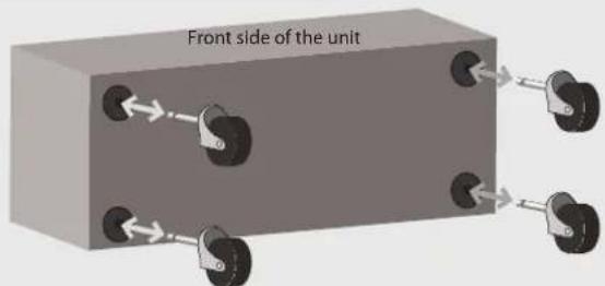
In every situation where the unexpected movement of this unit could present a danger (such as when it's set up on a stage, or when it's being transported inside a vehicle), make sure to remove all the casters.

Avoid climbing on top of the unit, or placing heavy objects on it
Never climb on top of, nor place heavy objects on the unit.

Do not connect or disconnect the power cord with wet hands
Never handle the power cord or its plugs with wet hands when plugging into, or unplugging from, an outlet or this unit.

- Do not allow rubber, vinyl, or similar materials to remain on this unit for long periods of time. Such objects can discolor or otherwise harmfully affect the finish.
- Do not paste stickers, decals, or the like to this instrument. Peeling such matter off the instrument may damage the exterior finish.
- Depending on the material and temperature of the surface on which you place the unit, its rubber feet may discolor or mar the surface. You can place a piece of felt or cloth under the rubber feet to prevent this from happening. If you do so, please make sure that the unit will not slip or move accidentally.
- Do not put anything that contains water on this unit. Also, avoid the use of insecticides, perfumes, alcohol, nail polish, spray cans, etc., near the unit. Swiftly wipe away any liquid that spills on the unit using a dry, soft cloth.
Maintenance
- To clean the unit, use a dry, soft cloth; or one that is slightly dampened. Try to wipe the entire surface using an equal amount of strength. Rubbing too hard in the same area can damage the finish.
- Never use benzine, thinners, alcohol or solvents of any kind, to avoid the possibility of discoloration and/or deformation.
Repairs and Data
- Please be aware that all data contained in the unit's memory may be lost when the unit is sent for repairs. Important data should always be written down on paper (when possible). During repairs, due care is taken to avoid the loss of data. However, in certain cases (such as when circuitry related to memory itself is out of order), we regret that it may not be possible to restore the data, and Roland assumes no liability concerning such loss of data.
Additional Precautions
- Please be aware that the contents of memory can be irretrievably lost as a result of a malfunction, or the improper operation of the unit. To protect yourself against the risk of loosing important data, we recommend that you periodically write down the settings stored in the unit's memory on paper.
- Unfortunately, it may be impossible to restore the contents of data that was stored in the unit's memory once it has been lost. Roland Corporation assumes no liability concerning such loss of data.
CAUTION
Disconnect everything before moving the unit
Before moving the unit, disconnect the power plug from the outlet, and pull out all cords from external devices.

Unplug the power cord from the outlet before cleaning
Before cleaning the unit, turn it off and unplug the power cord from the outlet (p. 6).

If there is a possibility of lightning strike, disconnect the power cord from the outlet
Whenever you suspect the possibility of lightning in your area, pull the plug on the power cord out of the outlet.

Do not remove the speaker grille and speaker
Do not remove the speaker grille and speaker by any means. Speaker not user replaceable. Shock hazardous voltages and currents are present inside the enclosure.

- Use a reasonable amount of care when using the unit's buttons, sliders, or other controls; and when using its jacks and connectors. Rough handling can lead to malfunctions.
- When disconnecting all cables, grasp the connector itself—never pull on the cable. This way you will avoid causing shorts, or damage to the cable's internal elements.
- A small amount of heat will radiate from the unit during normal operation.
- To avoid disturbing others nearby, try to keep the unit's volume at reasonable levels.
- When you need to transport the unit, package it in the box (including padding) that it came in, if possible. Otherwise, you will need to use equivalent packaging materials.
- Use only the specified expression pedal (Roland EV-5, BOSS FV-500L, BOSS FV-500H; sold separately). By connecting any other expression pedals, you risk causing malfunction and/or damage to the unit.
- Some connection cables contain resistors. Do not use cables that incorporate resistors for connecting to this unit. The use of such cables can cause the sound level to be extremely low, or impossible to hear. For information on cable specifications, contact the manufacturer of the cable.
- Roland, BOSS, COSM are either registered trademarks or trademarks of Roland Corporation in the United States and/or other countries.
- Company names and product names appearing in this document are registered trademarks or trademarks of their respective owners.
- MMP (Moore Microprocessor Portfolio) refers to a patent portfolio concerned with microprocessor architecture, which was developed by Technology Properties Limited (TPL). Roland has licensed this technology from the TPL Group.
- This product contains eCROS integrated software platform of eSOL Co., Ltd. eCROS is a trademark of eSOL Co., Ltd. in Japan.
Copyright
Front Panel
PROGRESSIVE AMP
PROGRESSIVE AMP is an original amp designed with the very latest COSM technology. By changing the preamp and power amp behavior, you can freely create a broad range of sounds.
[DRIVE] knob/
[BOOST] button
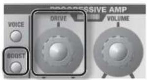
Adjusts the level of distortion.
| [BOOST] button | [DRIVE] knob Operation Minimum Value to Maximum Value |
| OFF Clean to | Crunch |
| ON Crunch to | Super Extreme |
* When BOOST is on, the expression pedal connected to the DRIVE jack of the exclusive foot controller (p. 8) can change the sound from clean to super extreme.
[VOICE] button
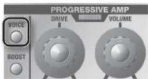
Changes sound character.
[VOLUME] knob
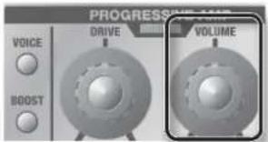
Adjusts the volume.
Sound indicator

When distortion is adjusted with the [DRIVE] knob, the sound indicator color changes according to the level of the distortion. (If you don't want to use the LED display, for example, on a dark stage, it can be turned off.)
To make the setting, see p. 10
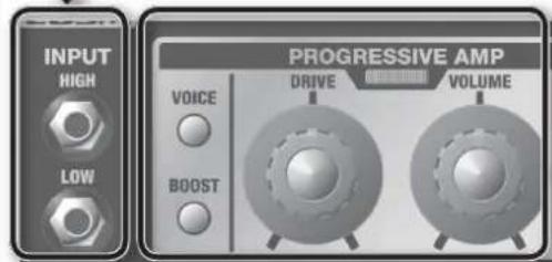
INPUT Jacks
Use to connect to an electric guitar. Use HIGH or LOW according to the guitar's output level. Normally connect to HIGH. Especially for guitars with a large output and likely sound distortion, connect to LOW.
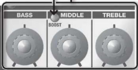
[MID BOOST] Button
Turns the midrange boost on/off.
[BASS] Knob
Adjusts the sound level of the lower range.
[MIDDLE] Knob
Adjusts the sound level of the midrange.
[TREBLE] Knob
Adjusts the sound level of the upper range.
[MANUAL] Button, [CH 1]-[CH 4] Buttons
Each knob on the front panel of GA-212/GA-112 has an original LED pointer that allows you to check at a glance the settings during a performance or when the channels have been changed.
The simply-structured operation system enables intuitive control.
[MANUAL] button
When the unit is turned on, MANUAL operation is activated.
In MANUAL operation the LED pointers and knobs always match.


Knob LED pointers
An LED pointer indicates the setting of a knob.
When any one of the [CH 1]–[CH 4] buttons are pressed to change the channel (settings), the knob LED pointers also change instantaneously.
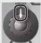
When the [MANUAL] button is pressed, the LED pointers will be displayed at the current knob positions.
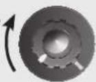
If the saved knob setting is at the maximum level and the knob position is at the minimum level, turn the knob clockwise before making adjustments to lower the set value. If the opposite is true, turn the knob counterclockwise before making adjustments to raise the set value.

flowchart
graph TD
    A["[EFX LOOP A"] Button, [EFX LOOP B] Button\nSwitches on/off any external effects unit connected to the EFX LOOP A/B jacks on the rear panel.] --> B["[PRESENCE"] Knob\nGives a lustrous contour to the mid and upper ranges. This gives a clear, open sound.]
    B --> C["[REVERB"] Knob\nAdjusts the level of reverb.]
    C --> D["Master GA-212 ON"]
    D --> E["[MASTER"] Knob\nAdjusts the overall volume.]
    E --> F["Ch 3 CH 4"]
[ON] Switch
This switches the unit on/off.
Switching the unit on
* Once everything is properly connected (p. 6), be sure to follow the procedure below to turn on their power. If you turn on equipment in the wrong order, you risk causing malfunction or equipment failure.
* Before turning the unit on/off, always be sure to turn the volume down. Even with the volume turned down, you might hear some sound when switching the unit on/off. However, this is normal and does not indicate a malfunction.
* This unit is equipped with a protection circuit. A brief interval (a few seconds) after turning the unit on is required before it will operate normally.
- Turn on all the devices connected, but not the device connected to the LINE OUT jack.
- Turn on the GA-212/GA-112.
- Turn on the device connected to the LINE OUT jack.
Switching the unit off
- Before switching off the unit, lower the volume on all the devices and then turn off the devices in the reverse order to which they were switched on.
CAUTION
* With the factory settings, the GA-212/GA-112 will automatically be switched off 4 hours after you stop playing or operating the unit. If you don't want the unit to turn off automatically, set the [AUTO OFF] switch to "OFF" as described on p. 6.
* If you need to turn off the power completely, first turn off the unit, then unplug the power cord from the power outlet. Refer to Power Supply (p. 3).
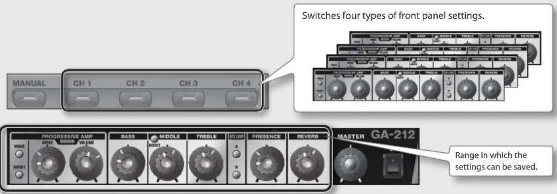
[CH 1]–[CH 4] buttons
Excluding the [MASTER] knob, the settings of all knobs and buttons on the front panel are saved in the [CH 1]–[CH 4] buttons. This function saves the last positions of the knobs; therefore, there is no special operation needed to save the settings.
Copying the button settings
You can copy the settings of the [MANUAL] button, or each of the [CH 1]–[CH 4] buttons to another channel.
![1 Hold down the button to be copied, i.e. the [MANUAL] button or any of the [CH 1]–[CH 4] buttons... 2 Select and press any of the [CH 1]–[CH 4] buttons to which a copy will be made. MANUAL CH 1 CH 2 CH 3 CH 4](/content/2026/04/671526/images/738afb9e5d5838f30f02d9e818bb7d4925e1f0e9917b03f08b90ac6ec74e0f91.jpg)
* You cannot select the [MANUAL] button as the channel which will receive the copy.
Saving the channel settings using the write operation function
The automatic saving of channel settings can be changed to the saving of channel settings by using the write operation. In the write operation mode, by holding down any one of the [CH 1]–[CH 4] buttons for a few seconds, the settings can be saved.
To make the setting, see
p. 10
Rear Panel (Connecting Equipment)
AC IN Jack
Connect the provided power cord to this jack.
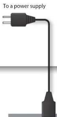
FOOT CONTROL/LINK IN, LINK OUT Jacks
FOOT CONTROL jack
This is for connecting a stereo cable to the GA FOOT CONTROL jack of the foot controller.
* Always use a stereo cable.

natural_image
Exterior view of a modern office building (no signage)LINK IN jack/LINK OUT jack
Use these jacks to make link connections for GAs.
For details, see

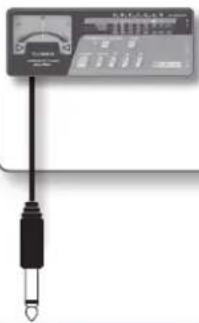
THRU/TUNER OUT Jack
A guitar's direct sound from the INPUT jack is output. Use this to make unit link connections.
For details, see

A tuner can also be connected.
natural_image
Pure electrical circuit lines without any symbols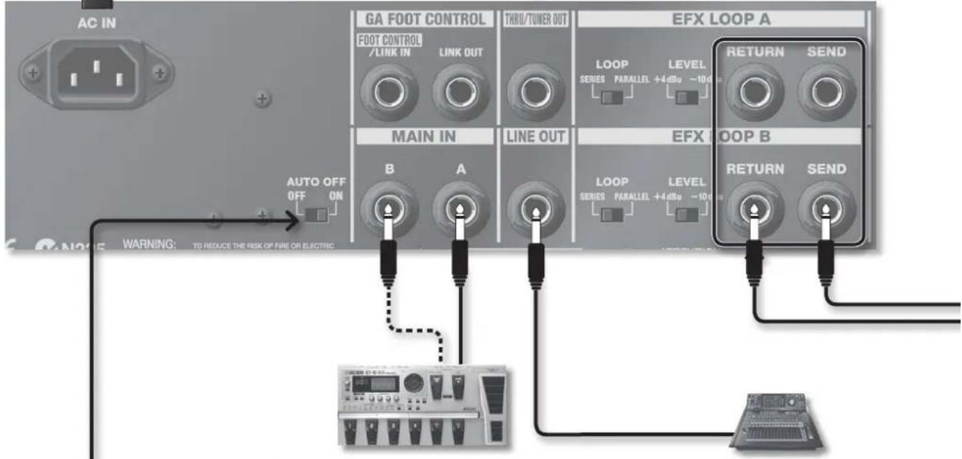
[AUTO OFF] Switch
CAUTION
This switch controls the AUTO OFF function that automatically switches off the unit after the fixed time has elapsed.
When the AUTO OFF function is switched on, the unit will automatically be turned off approximately 4 hours after last use.
If you don't want the unit to turn off automatically, set the switch to OFF.
To turn the unit back on after the AUTO OFF function has turned the unit off, turn the [ON] switch back on (p. 5), or set the [AUTO OFF] switch to OFF.
MAIN IN Jacks
To output the sound created with a multi-effects unit or other devices, connect to the MAIN IN jacks.
GA-212 plays the A jack input sound from the left speaker, and the B jack input sound from the right speaker. When only the A jack is used, the same sound is played from the right and left speakers. When only the B jack is used, sound is only played from the right speaker.
GA-112 mixes the A and B jack input sounds and plays from the speaker.
CAUTION
* If the AUTO OFF function is switched on, and only the signals from the MAIN IN jack are input with no other operation, after approximately 4 hours the unit is automatically turned off.
LINE OUT Jack
This is for connecting a PA system, recorder or other external equipment.
EFX LOOP A, B Jacks
These are for connecting external effects units.
There are two systems, A and B (monaural).
Connect the external effects unit INPUT to the SEND jack, and the OUTPUT to the RETURN jack.
[LOOP] switch
When PARALLEL is set, the external effects sound and the direct sound are mixed.
When SERIES is set, only the external effects sound is played.
* When SERIES is set, if the volume of the external effects unit is turned down completely, or the power is not turned on, no sound will be heard.
[LEVEL] switch
Use this switch to change the input/output level of an effects loop. According to the input/output level of the connected equipment, select +4 dBu or -10 dBu. When the input/output level of the connected equipment is high, set +4 dBu, and when it is low, set -10 dBu.
* Depending on the power supply you are using, the two cables connected to SEND and RETURN may pick up more noise if they are placed apart from each other. Bundle the cables together.
External effects unit
OUTPUTINPUT
\*1 Important Notes on FOOT CONTROL/LINK IN and LINK OUT Jacks
- Do not connect any device other than GA-212/GA-112 for link connection or exclusive GA FOOT CONTROLLER (GA-FC) to the FOOT CONTROL/LINK IN jack.
- Do not connect any device other than GA-212/GA-112 for link connection to the LINK OUT jack.
- This instrument is equipped with balanced (TRS) type jacks. Wiring diagrams for these jacks are shown below.
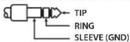
Exclusive Foot Controller (sold separately)
Connecting the foot controller
Connect a stereo cable to the FOOT CONTROL/LINK IN jack of the GA-212/GA-112.
* Always use a stereo cable.
* Use cables that do not contain resistors.

How to operate the foot controller
You can change channels by using the foot controller. By pressing the [FUNCTION] switch, you can also turn on/off BOOST, MID BOOST, EFX LOOP A, EFX LOOP B, and REVERB.
* The ON/OFF operation of BOOST, MID BOOST, EFX LOOP A, EFX LOOP B, and REVERB using the foot controller is not saved in the channel.

Using the expression pedals
By connecting expression pedals (Roland EV-5, BOSS FV-500L, BOSS FV-500H; sold separately), you can change the DRIVE value and volume by pedal.
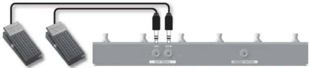
DRIVE jack
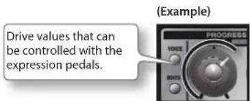
Use this to control DRIVE. When BOOST is off, the sound can be changed from clean to crunch, and when BOOST is on, changed from clean to super extreme.
With an expression pedal connected to the DRIVE jack, the drive value can be controlled from 0 to the current DRIVE value on the panel. When the pedal is pressed fully down, the drive value shown by the panel knob will be applied.
VOLUME jack
This is for controlling the volume. Volume swell and mute are possible.
* The volume that you can control with the expression pedal connected to this jack is different from the [VOLUME] on the panel. The pedal operation is not linked to the [VOLUME] knob level.
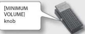
Setting MINIMUM VOLUME of an expression pedal
With the [MINIMUM VOLUME] knob of an expression pedal, you can set the value for when the pedal is lifted up all the way (lowest value).
DRIVE value settings after changing channel
When an expression pedal is connected to the DRIVE jack, you can set the DRIVE value after changing channel to the current pedal value, not the value saved in the channel. To make the setting, see p. 10
* Use only the specified expression pedal (Roland EV-5, BOSS FV-500L, BOSS FV-500H; sold separately). By connecting any other expression pedals, you risk causing malfunction and/or damage to the unit.
Making Unit Link Connections
Link connection can be made with another unit. Link connection allows you to obtain more sound pressure, and give a powerful performance on a large stage.
When the amps are connected as described below, channel change by the foot controller, and use of an expression pedal are possible with the connected amp.
![Rear panel GA FOOT CONTROL THRU/TOWER OUT EFX LOOP A FOOT CONTROL LINK IN LINK OUT LOOP LEVEL RETURN SEN SERIES PARALLEL +2.0Hz -10 dBu To the foot controller Cable: Stereo 1/4-inch phone type Cable: 1/4-inch phone type Rear panel GA FOOT CONTROL THRU/TOWER OUT FOOT CONTROL LINK IN LINK OUT Front panel * Before making a connection, turn the [MASTER] knob of the amp to be connected to 0. Adjust the volume after making the connection. * When the guitar is connected to HIGH, connect to HIGH. When the guitar is connected to LOW, connect to LOW. * Lower the volume on all devices when turning the unit on or off. * Lower the volume on all devices when turning the unit on or off.](/content/2026/04/671526/images/0530d685acfd13c883aea49b196fc5aff043d21170095e1bcae370773e60f9a2.jpg)
How to stack the amps
GA-212/112 can be used in a stacked configuration.
NOTE
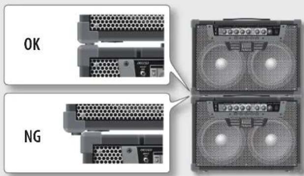
Up to one unit can be stacked. Do not stack two or more units. When stacking, be sure to follow the instructions below.

* Be sure to set up and use these units in stable, level locations.
* To prevent injury caused by the unit overturning or being dropped, make sure that at least two persons work together when lifting and carrying the units.
* Be careful not to get your fingers pinched.
How to stack the amps
* When the amps are stacked, always align them so that the corners of the upper and lower amps are securely engaged. If the corners are not engaged, there is a risk of the units falling.
* Do not stack GA-212 and GA-112.
* If the units are to be stacked, always remove all casters from each amp.
Fitting and removal of casters (For GA-212 only)
The casters are not fitted to the unit when shipped from the factory. To fit or remove the casters, follow the diagram.
Other Settings
By holding down specific buttons and switching the unit on simultaneously, the following settings can be configured for the unit.
| Settings Operation | ||
| Returning to the factory-default settings (*) | Hold down the [EFX LOOP B] and [CH4] buttons, and switch the unit on. | |
| Saving to a channel | Automatically saving the channel settings (default) | Hold down the [EFX LOOP A] button, and switch the unit on. |
| Saving the channel settings using the write operation function (p. 5) | Hold down the [EFX LOOP B] button, and switch the unit on. | |
| DRIVE value after changing the channel | The value saved in a channel (default) Hold down the operation function (p. 5) | [VOICE] button, and switch the unit on. |
| Current expression pedal value Hold down the [BOOST] button, and switch the unit on. | ||
| Sound indicator | Enabling color display (default) Hold down the [MID] | BOOST] and [VOICE] buttons, and switch the unit on. |
| Disabling color display Hold down the [MID BOOST] | and [BOOST] buttons, and switch the unit on. | |
| Setting the Link mode* The second amplifier functions according to the settings on the first amplifier. | The second amplifier reflects the foot controller operation (channel switching, expression pedal, and On/Off of REVERB) (default) | Hold down the [EFX LOOP A] and [MID BOOST] buttons, and switch the unit on. |
| The second amplifier reflects all operations on the front panel (except MASTER) and foot controller | Hold down the [EFX LOOP B] and [MID BOOST] buttons, and switch the unit on. | |
| Copy the channel settings on the first amplifier to the second amplifier | With the second amplifier turned on, hold down the [EFX LOOP A], [EFX LOOP B], and [MID BOOST] buttons on the first amplifier, and switch the unit on. | |
* The settings for each channel also return to the factory-default settings.
Block Diagram
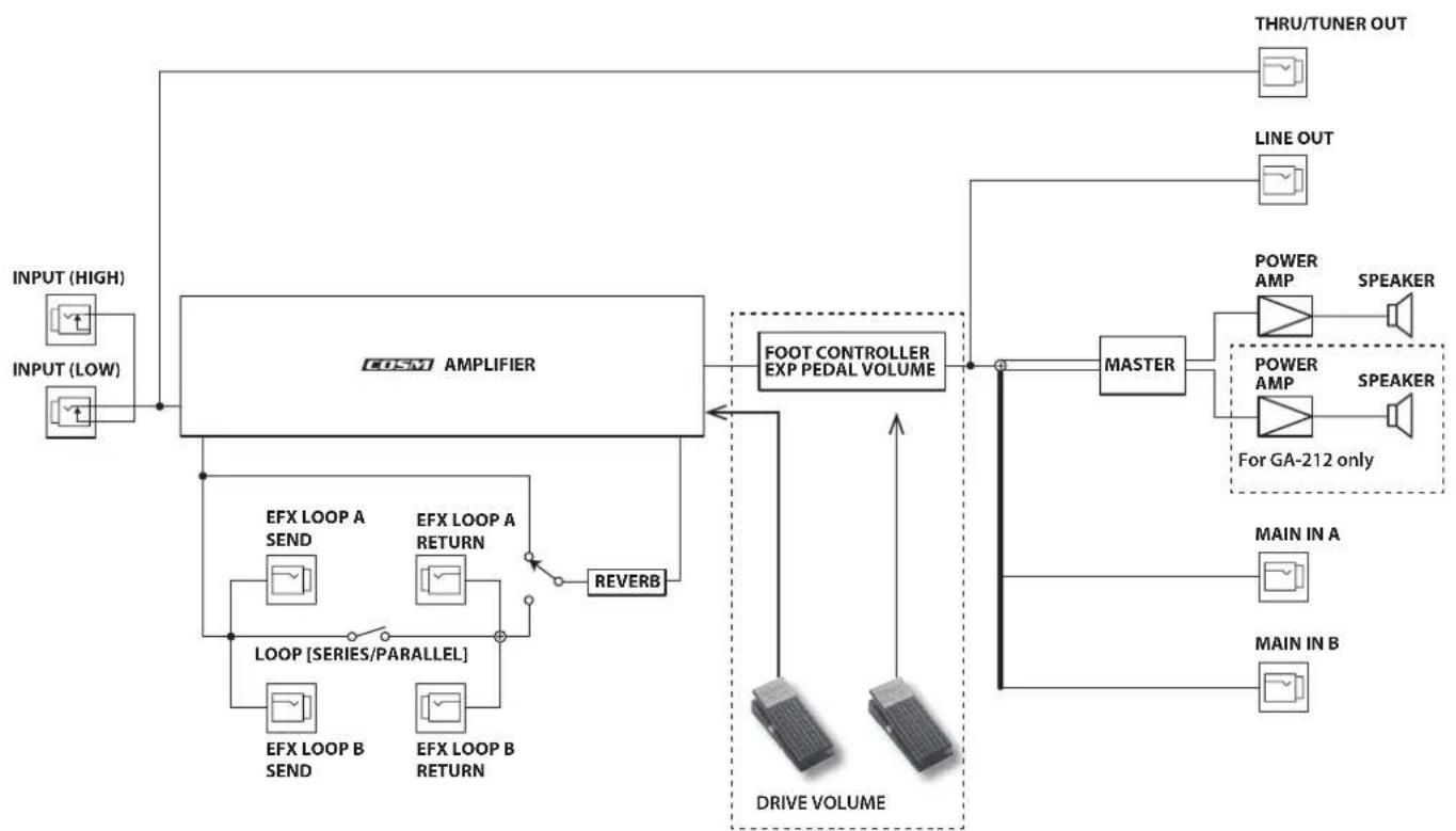
flowchart
graph TD
    A["INPUT (HIGH)"] --> B["COSM AMPLIFIER"]
    C["INPUT (LOW)"] --> B
    B --> D["FOOT CONTROLLER EXP PEDAL VOLUME"]
    D --> E["MASTER"]
    E --> F["POWER AMP"]
    E --> G["POWER AMP"]
    F --> H["SPEAKER"]
    G --> I["SPEAKER"]
    J["THRU/TUNER OUT"] --> K["LINE OUT"]
    L["DRIVE VOLUME"] --> M["EMPIRE"]
    N["EMPIRE"] --> O["EMPIRE"]
    P["EMPIRE"] --> Q["EMPIRE"]
    R["EMPIRE"] --> S["EMPIRE"]
    T["EMPIRE"] --> U["EMPIRE"]
    V["EMPIRE"] --> W["EMPIRE"]
    X["EMPIRE"] --> Y["EMPIRE"]
    Z["EMPIRE"] --> AA["EMPIRE"]
    AB["EMPIRE"] --> AC["EMPIRE"]
    AD["EMPIRE"] --> AE["EMPIRE"]
    AF["EMPIRE"] --> AG["EMPIRE"]
    AH["EMPIRE"] --> AI["EMPIRE"]
    AJ["EMPIRE"] --> AK["EMPIRE"]
    AL["EMPIRE"] --> AM["EMPIRE"]
    AN["EMPIRE"] --> AO["EMPIRE"]
    AP["EMPIRE"] --> AQ["EMPIRE"]
    AR["EMPIRE"] --> AS["EMPIRE"]
    AT["EMPIRE"] --> AU["EMPIRE"]
    AV["EMPIRE"] --> AW["EMPIRE"]
    AX["EMPIRE"] --> AY["EMPIRE"]
    AZ["EMPIRE"] --> BA["EMPIRE"]
    BB["EMPIRE"] --> BC["EMPIRE"]
    BD["EMPIRE"] --> BE["EMPIRE"]
    BF["EMPIRE"] --> BG["EMPIRE"]
    BH["EMPIRE"] --> BI["EMPIRE"]
    BJ["EMPIRE"] --> BK["EMPIRE"]
    BL["EMPIRE"] --> BM["EMPIRE"]
    BN["EMPIRE"] --> BO["EMPIRE"]
    BP["EMPIRE"] --> BQ["EMPIRE"]
    BR["EMPIRE"] --> BS["EMPIRE"]
    BT["EMPIRE"] --> BU["EMPIRE"]
    BV["EMPIRE"] --> BW["EMPIRE"]
    BX["EMPIRE"] --> BY["EMPIRE"]
    BZ["EMPIRE"] --> CA["EMPIRE"]
    CB["EMPIRE"] --> CC["EMPIRE"]
    CD["EMPIRE"] --> CE["EMPIRE"]
    CF["EMPIRE"] --> CG["EMPIRE"]
    CH["EMPIRE"] --> CI["EMPIRE"]
    CJ["EMPIRE"] --> CK["EMPIRE"]
    CE --> CR["Power AMP"]
    CE --> CS["Power AMP"]
    CE --> CT["SPEAKER"]
    CU["MAIN IN A"] --> CV["SPEAKER"]
    CW["SPEAKER"] --> CX["SPEAKER"]
Only when the foot controller is connected
Roland GA-212
Roland GA-112: Guitar Amplifier
| GA-212 GA-112 | ||
| Rated Power Output 200 W 100 W | ||
| Nominal Input Level | INPUT HIGH: 10 dBu | |
| INPUT LOW: 0 dBu | ||
| MAIN IN A, B: -10 dBu | ||
| EFX LOOP A, B RETURN: -10 dBu, +4 dBu (selectable) | ||
| Nominal Output Level | LINE OUT: -10 dBu | |
| EFX LOOP A, B SEND: -10 dBu, +4 dBu (selectable) | ||
| THRU / TUNER OUT: -10 dBu | ||
| Speaker 30 cm (12 inches) x 2 30 cm (12 inches) x 1 | ||
| Controls | [ON] switch[AUTO OFF] switch[VOICE] button[BOOST] button[MID BOOST] buttonEFX LOOP[A],[B] buttonEFX LOOP A, B[LOOP] switchesEFX LOOP A, B[LEVEL] switches[MANUAL] button[CH 1]-[CH 4] button | |
| [MASTER] knob[DRIVE] knob[VOLUME] knob[BASS] knob[MIDDLE] knob[TREBLE] knob[PRESENCE] knob[REVERB] knob | ||
| Indicators | SOUND INDICATORLED knobx7 (except MASTER Knob)VOICEBOOSTMID BOOSTEFX LOOP A, BMANUALCH 1-CH 4 | |
| Connectors | AC IN jackINPUT HIGH/LOW jacks (1/4-inch phone type)MAIN IN A, B jacks (1/4-inch phone type)LINE OUT jack (1/4-inch phone type)FOOT CONTROL/LINK IN jack (Stereo 1/4-inch phone type)LINK OUT jack (Stereo 1/4-inch phone type)THRU/TUNER OUT jack (1/4-inch phone type)EFX LOOP A, B SEND jacks (1/4-inch phone type)EFX LOOP A, B RETURN jacks (1/4-inch phone type) | |
| Power Consumption 75 W 45 W | ||
| Dimensions | 715 (W) x 337 (D) x 560 (H) mm28-3/16 (W) x 13-5/16 (D) x 22-1/16 (H) inches | 615 (W) x 337 (D) x 504 (H) mm24-1/4 (W) x 13-5/16 (D) x 19-7/8 (H) inches |
| Weight 32.0 kg / 70 lbs 9 oz 24.5 kg / 54 lbs 1 oz | ||
| Accessories | Caster x 4 (only GA-212)Power CordOwner's Manual | |
| Options(sold separately) | GA FOOT CONTROLLER (GA-FC) | |
* 0 dBu = 0.775 Vrms
* In the interest of product improvement, the specifications and/or appearance of this unit are subject to change without prior notice.
Roland
natural_image
Front view of a Poland audio amplifier with visible grille and buttons (no text or symbols on body)natural_image
Front view of a Roland audio amplifier with visible sound wave and control knobs (no text or symbols on body)[BASS]-Regler
Buchsen FOOT CONTROL/LINK IN, LINK OUT
FOOT CONTROL-Buchse
natural_image
Exterior view of a modern office building (no signage)Buchse LINK IN/LINK OUT
natural_image
Pure electrical circuit lines without any symbols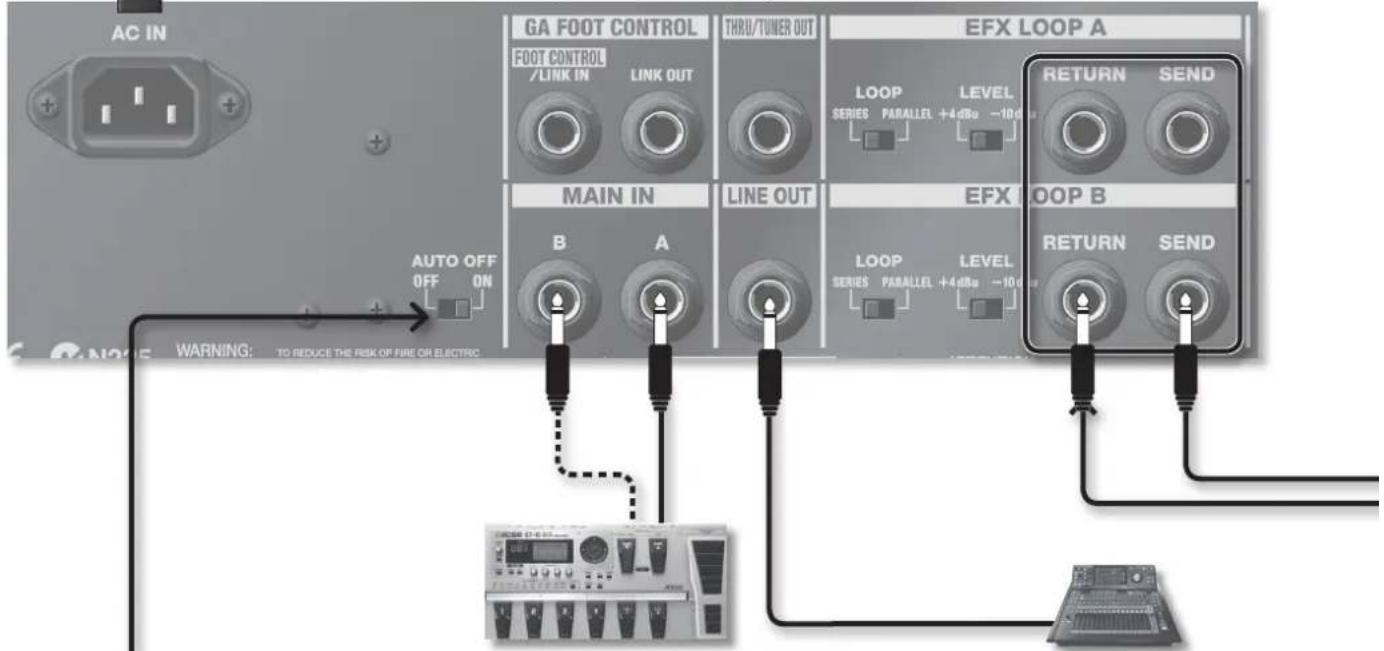
[AUTO OFF]-Schalter
⚠ VORSICHT
natural_image
Pure electrical circuit lines without any symbolsDRIVE-Buchse
natural_image
Front view of a Poland audio amplifier with visible grille and buttons (no text or symbols on body)natural_image
Front view of a Roland audio amplifier with visible sound wave and control knobs (no text or symbols)Bouton [BASS]
natural_image
Simple line drawing of a lamp with three leads and a base, no text or symbols presentPrises FOOT CONTROL/LINK IN, LINK OUT
Prise FOOT CONTROL
natural_image
Exterior view of a modern office building (no signage)Prise LINK IN/priseLINK OUT
natural_image
Close-up of a digital multimeter with a black terminal connector (no visible text or symbols)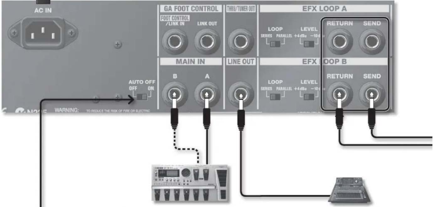
Commutateur [AUTO OFF]
![ROLAND GA-212 - Commutateur [AUTO OFF] - 1](/content/2026/04/671526/images/f541d5eda6a4b5f786ff883da016a882b9634c8f6926b55d04a2f1e4442da5e5.jpg)
ATTENTION
Prise DRIVE
natural_image
Front view of a Poland audio amplifier with visible sound waves and control knobs (no text or symbols)natural_image
Front view of a Roland audio amplifier with visible sound wave and control knobs (no text or symbols on body)Manopola [BASS]
Jack FOOT CONTROL/LINK IN, LINK OUT
Jack FOOT CONTROL
natural_image
Exterior view of a gray industrial control panel with two buttons and a highlighted square (no visible text or symbols)Jack LINK IN /jack LINK OUT
natural_image
Pure electrical circuit lines without any symbols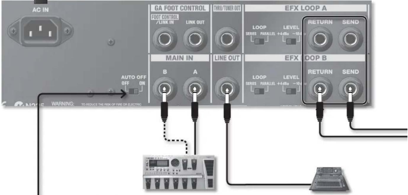
Controllo del foot controller
natural_image
Pure electrical circuit lines without any symbolsJack DRIVE
natural_image
Front view of a Poland audio amplifier with visible grille and buttons (no text or symbols on body)natural_image
Front view of a Roland audio amplifier with visible sound wave and control knobs (no text or symbols)Mando [BASS]
Botón [MANUAL], botones [CH 1]–[CH 4]
![ROLAND GA-212 - Botón [MANUAL], botones [CH 1]–[CH 4] - 1](/content/2026/04/671526/images/5d245efc1244c10563ad36f1f574ac722e5c2d43856415c85e94d9517adfe385.jpg)
natural_image
Simple line drawing of a black electrical plug with two leads, no text or symbols presentConectores FOOT CONTROL/LINK IN, LINK OUT
Conector FOOT CONTROL
natural_image
Exterior view of a gray industrial control panel with two buttons and a highlighted square (no visible text or symbols)Conector LINK IN/conector LINK OUT
natural_image
Close-up of a digital multimeter with a black terminal connector (no visible text or symbols)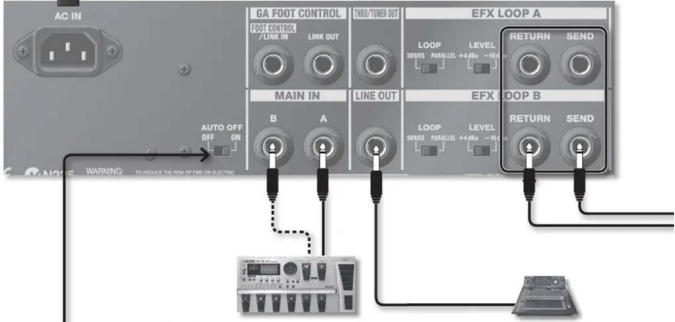
Conector DRIVE
natural_image
Front view of a Poland audio amplifier with visible grille and buttons (no text or symbols on body)natural_image
Front view of a Roland audio amplifier with visible sound wave and control knobs (no text or symbols)Botão [BASS]
Conectores FOOT CONTROL/LINK IN, LINK OUT
Conector FOOT CONTROL
natural_image
Two gray industrial control panel units with indicator lights, one showing a display (no visible text or symbols)Conector LINK IN/conector LINK OUT
natural_image
Pure electrical circuit lines without any symbols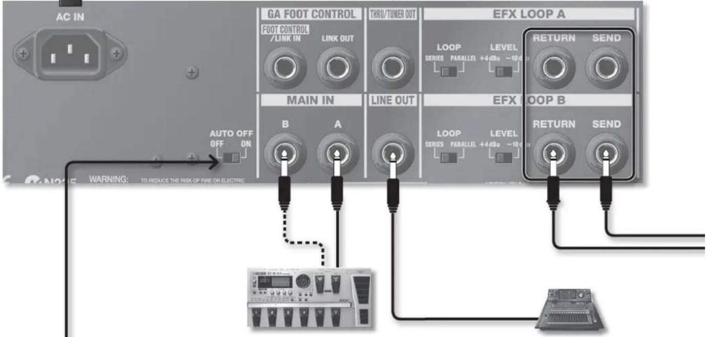
Chave [AUTO OFF]
CUIDADO
Como operar o pedal de controle
natural_image
Diagram of an electronic device showing two input terminals connected to a central interface with three labeled pins (no text or symbols on the components themselves)Conector DRIVE
natural_image
Front view of a Poland audio amplifier with visible sound waves and control knobs (no text or symbols)natural_image
Front view of a Roland audio amplifier with visible sound waves and control knobs (no text or symbols)[BASS]-regelaar
natural_image
Simple line drawing of a black electrical plug with two leads, no text or symbols presentFOOT CONTROL/LINK IN-, LINK OUT-aansluitingen
natural_image
Two gray industrial control panel buttons with icons, one displaying a circular icon and the other a square button (no text or symbols visible)natural_image
Pure electrical circuit lines without any symbols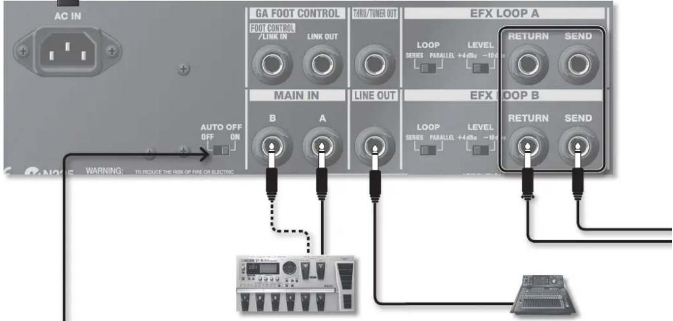
[AUTO OFF]-schakelaar
OPGELET
De footcontroller bedienen
This product complies with the requirements of EMCD 2004/108/EC and LVD 2006/95/EC.
-For the USA
FEDERAL COMMUNICATIONS COMMISSION RADIO FREQUENCY INTERFERENCE STATEMENT
This equipment has been tested and found to comply with the limits for a Class B digital device, pursuant to Part 15 of the FCC Rules. These limits are designed to provide reasonable protection against harmful interference in a residential installation. This equipment generates, uses, and can radiate radio frequency energy and, if not installed and used in accordance with the instructions, may cause harmful interference to radio communications. However, there is no guarantee that interference will not occur in a particular installation. If this equipment does cause harmful interference to radio or television reception, which can be determined by turning the equipment off and on, the user is encouraged to try to correct the interference by one or more of the following measures:
– Reorient or relocate the receiving antenna.
– Increase the separation between the equipment and receiver.
- Connect the equipment into an outlet on a circuit different from that to which the receiver is connected.
- Consult the dealer or an experienced radio/TV technician for help.
This device complies with Part 15 of the FCC Rules. Operation is subject to the following two conditions:
(1) this device may not cause harmful interference, and
(2) this device must accept any interference received, including interference that may cause undesired operation.
This equipment requires shielded interface cables in order to meet FCC class B limit.
Any unauthorized changes or modifications not expressly approved by the party responsible for compliance could void the user's authority to operate the equipment.
For Canada
NOTICE
This Class B digital apparatus meets all requirements of the Canadian Interference-Causing Equipment Regulations.
AVIS
This product contains chemicals known to cause cancer, birth defects and other reproductive harm, including lead.
For EU Countries


This symbol indicates that in EU countries, this product must be collected separately from household waste, as defined in each region. Products bearing this symbol must not be discarded together with household waste.

When you need repair service, call your nearest Roland Service Center or authorized Roland distributor in your country as shown below.
AFRICA
EGYPT
Al Fanny Trading Offi ce
9, EBN Hagar Al Askalany Street,
ARD E1 Golf, Heliopolis,
Cairo 11341, EGYPT
TEL:(022)-417-1828
REUNION
MARCEL FO-YAM Sarl
Royal Cape Park, Unit 24
Londonderry Road, Ottery 7800
Cape Town, SOUTH AFRICA
TEL:(021)7994900
ASIA
CHINA
Roland Shanghai Electronics
Co., Ltd.
5F. No.1500 Pingliang Road
Shanghai 200090, CHINA
TEL:(021)5580-0800
Roland Shanghai Electronics
Co., Ltd. (BEIJING OFFICE)
3F, Soluxe Fortune Building
63 West Dawang Road, Chaoyang
District, Beijing, CHINA
TEL: (010) 5960-2565
HONG KONG
Tom Lee Music
11/F Silvercord Tower 1
30 Canton Rd
Tsimshatsui, Kowloon,
HONG KONG
TEL: 852-2737-7688
Parsons Music Ltd.
8th Floor, Railway Plaza, 39
Chatham Road South, T.S.T.
Kowloon, HONG KONG
TEL:852-2333-1863
INDIA
Rivera Digitec (India) Pvt. Ltd.
411, Nirman Kendra Mahalaxmi
Flats Compound Off. Dr. Edwin
Moses Road, Mumbai-400011,
INDIA
TEL:(022) 2493 9051
INDONESIA
PT. Citra Intirama
Ruko Garden Shopping Arcade
Unit 8 CR, Podomoro City
JI.Letjend. S.Parman Kav.28
Jakarta Barat 11470, INDONESIA
TEL:(021)3698-331
KOREA
Cosmos Corporation
1461-9, Seocho-Dong,
Seocho Ku, Seoul, KOREA
TEL: (02) 3486-8855
MALAYSIA/
SINGAPORE
Roland Asia Pacific Sdn. Bhd.
45-1, Block C2, Jalan PJU 1/39,
Dataran Prima, 47301 Petaling
Jaya, Selangor, MALAYSIA
TEL:(03)7805-3263
PHILIPPINES
G.A. Yupangco & Co. Inc.
339 Gil J. Puyat Avenue
Makati, Metro Manila 1200,
PHILIPPINES
TEL: (02) 899 9801
TAIWAN
ROLAND TAIWAN ENTERPRISE
CO., LTD.
9F-5, No. 112 Chung Shan
North Road Sec. 2 Taipei 104,
TAIWAN R.O.C.
TEL: (02) 2561 3339
THAILAND
Theera Music Co., Ltd.
100-108 Soi Verng Nakornkasem,
New Road, Sumpantawong,
Bangkok 10100, THAILAND
TEL: (02) 224-8821
VIET NAM
VIET THUONG CORPORATION
386 CACH MANG THANG TAM ST.
DIST.3, HO CHI MINH CITY,
VIET NAM TEL: 19015
TEL: (08) 9316540
OCEANIA
AUSTRALIA/
NEW ZEALAND
Roland Corporation
Australia Pty., Ltd.
38 Campbell Avenue
Dee Why West. NSW 2099,
For Australia
TEL: (02) 9982 8266
For New Zealand
TEL: (09) 3098 715
CENTRAL/LATIN AMERICA
ARGENTINA
Instrumentos Musicales S.A.
Av.Santa Fe 2055
(1123) Buenos Aires, ARGENTINA
TEL:(011)4508-2700
BARBADOS
A&B Music Supplies LTD
12 Webster Industrial Park
Wildey, St. Michael, BARBADOS
TEL: (246) 430-1100
BRAZIL
Roland Brasil Ltda.
Rua San Jose, 211
Parque Industrial San Jose
Cotia - Sao Paulo - SP, BRAZIL
TEL:(011)4615 5666
CHILE
Comercial Fancy II S.A.
Rut.: 96.919.420-1
Nataniel Cox #739, 4th Floor
Santiago - Centro, CHILE TEL: (02) 688-0510
TEL: (02) 688-9540
COLOMBIA
Centro Musical Ltda.
Cra 43 B No 25 A 41 Bododega 9
Medellin, COLOMBIA
TEL:(574)3812529
COSTA RICA
JUAN Bansbach Instrumentos
Musicales
Ave.1. Calle 11, Apartado 10237,
San Jose, COSTA RICA
TEL: 258-0211
CURACAO
Zeelandia Music Center Inc.
Orionweg 30
Curacao, Netherland Antilles
TEL: (305) 5926866
DOMINICAN REPUBLIC
Instrumentos Fernando Giraldez
Boulevard Andrews, Albrook,
Panama City, REP. DE PANAMA
TEL: 315-0101
PARAGUAY
155, New National Road
Patras 26442, GREECE
TEL: 2610 435400
HUNGARY
Roland East Europe Ltd.
E2 Calmount Park, Calmount
Avenue, Dublin 12,
Republic of IRELAND
TEL.(01)4294444
ITALY
Roland Italy S. p. A.
- Roland
- Owner's Manual
- GA-212 GA-112
- IMPORTANT SAFETY INSTRUCTIONS SAVE THESE INSTRUCTIONS
- Roland's PROGRESSIVE AMP technology gives a broader and richer guitar sound
- Intuitive operation
- Equipped with simple operation of basic functions and expandability
- What is COSM?
- AUTO OFF function
- About The Exclusive Foot Controller
- "What type of stage amplifier do guitarists really want?" After much intensive research and development, GA is Roland's answer.
- INSTRUCTIONS FOR THE PREVENTION OF FIRE, ELECTRIC SHOCK, OR INJURY TO PERSONS
- ALWAYS OBSERVE THE FOLLOWING
- ! WARNING
- Make sure that the power cord is grounded
- Do not disassemble or modify by yourself
- Do not repair or replace parts by yourself
- Do not use or store in the following types of locations
- Do not place in an unstable location
- Connect the power cord to an outlet of the correct
- voltage
- WARNING
- Use only the included power cord
- Do not bend the power cord or place heavy objects
- on it
- Avoid extended use at high volume
- Don't allow foreign objects or liquids to enter unit;
- never place containers with liquid on unit
- Turn off the unit if an abnormality or malfunction occurs
- Adults must provide supervision in places where children are present
- Do not drop or subject to strong impact
- Do not share an outlet with an unreasonable number of other devices
- Do not use overseas
- Do not connect the unit to an electrical outlet when there is condensation on or in it
- CAUTION
- Place in a well ventilated location
- Grasp the plug when connecting or disconnecting the power cord
- Periodically clean the power cord's plug
- IMPORTANT NOTES
- Power Supply
- Placement
- Manage cables for safety
- Remove all casters if mobility presents danger
- Avoid climbing on top of the unit, or placing heavy objects on it
- Do not connect or disconnect the power cord with wet hands
- Maintenance
- Repairs and Data
- Additional Precautions
- Disconnect everything before moving the unit
- Unplug the power cord from the outlet before cleaning
- If there is a possibility of lightning strike, disconnect the power cord from the outlet
- Do not remove the speaker grille and speaker
- Copyright
- Front Panel
- PROGRESSIVE AMP
- INPUT Jacks
- [MID BOOST] Button
- [BASS] Knob
- [MIDDLE] Knob
- [TREBLE] Knob
- [MANUAL] Button, [CH 1]-[CH 4] Buttons
- [MANUAL] button
- Knob LED pointers
- [ON] Switch
- Switching the unit on
- Switching the unit off
- [CH 1]–[CH 4] buttons
- Copying the button settings
- Saving the channel settings using the write operation function
- Rear Panel (Connecting Equipment)
- AC IN Jack
- FOOT CONTROL/LINK IN, LINK OUT Jacks
- FOOT CONTROL jack
- LINK IN jack/LINK OUT jack
- THRU/TUNER OUT Jack
- [AUTO OFF] Switch
- When the AUTO OFF function is switched on, the unit will automatically be turned off approximately 4 hours after last use.
- MAIN IN Jacks
- LINE OUT Jack
- EFX LOOP A, B Jacks
- [LOOP] switch
- [LEVEL] switch
- \*1 Important Notes on FOOT CONTROL/LINK IN and LINK OUT Jacks
- Exclusive Foot Controller (sold separately)
- Connecting the foot controller
- How to operate the foot controller
- Using the expression pedals
- DRIVE jack
- VOLUME jack
- Setting MINIMUM VOLUME of an expression pedal
- DRIVE value settings after changing channel
- Making Unit Link Connections
- How to stack the amps
- NOTE
- Fitting and removal of casters (For GA-212 only)
- Other Settings
- Block Diagram
- Roland GA-212
- Roland GA-112: Guitar Amplifier
- [BASS]-Regler
- Buchsen FOOT CONTROL/LINK IN, LINK OUT
- FOOT CONTROL-Buchse
- Buchse LINK IN/LINK OUT
- [AUTO OFF]-Schalter
- ⚠ VORSICHT
- DRIVE-Buchse
- Bouton [BASS]
- Prises FOOT CONTROL/LINK IN, LINK OUT
- Prise FOOT CONTROL
- Prise LINK IN/priseLINK OUT
- Commutateur [AUTO OFF]
- ATTENTION
- Prise DRIVE
- Manopola [BASS]
- Jack FOOT CONTROL/LINK IN, LINK OUT
- Jack FOOT CONTROL
- Jack LINK IN /jack LINK OUT
- Controllo del foot controller
- Jack DRIVE
- Mando [BASS]
- Botón [MANUAL], botones [CH 1]–[CH 4]
- Conectores FOOT CONTROL/LINK IN, LINK OUT
- Conector FOOT CONTROL
- Conector LINK IN/conector LINK OUT
- Conector DRIVE
- Botão [BASS]
- Chave [AUTO OFF]
- CUIDADO
- Como operar o pedal de controle
- [BASS]-regelaar
- FOOT CONTROL/LINK IN-, LINK OUT-aansluitingen
- [AUTO OFF]-schakelaar
- OPGELET
- De footcontroller bedienen
- FEDERAL COMMUNICATIONS COMMISSION RADIO FREQUENCY INTERFERENCE STATEMENT
- NOTICE
- AVIS
- For EU Countries
- AFRICA
- EGYPT
- REUNION
- ASIA
- CHINA
- HONG KONG
- INDIA
- INDONESIA
- KOREA
- MALAYSIA/
- SINGAPORE
- PHILIPPINES
- TAIWAN
- THAILAND
- VIET NAM
- OCEANIA
- AUSTRALIA/
- NEW ZEALAND
- CENTRAL/LATIN AMERICA
- ARGENTINA
- BARBADOS
- BRAZIL
- CHILE
- COLOMBIA
- COSTA RICA
- TEL: 258-0211
- CURACAO
- DOMINICAN REPUBLIC
- PARAGUAY
- HUNGARY
- ITALY
Brand : ROLAND
Model : GA-212
Category : Guitar amp