P790 - Measuring equipment Dostmann Electronic - Free user manual and instructions
Find the device manual for free P790 Dostmann Electronic in PDF.


User questions about P790 Dostmann Electronic
0 question about this device. Answer the ones you know or ask your own.
Ask a new question about this device
Download the instructions for your Measuring equipment in PDF format for free! Find your manual P790 - Dostmann Electronic and take your electronic device back in hand. On this page are published all the documents necessary for the use of your device. P790 by Dostmann Electronic.
USER MANUAL P790 Dostmann Electronic
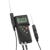
Precision 2-channel hand-held measuring instrument
text_image
Unit °C °F 0 L N R S T RH Prob PT J K L R T1-T2 CAL CoFF oP 1 oP 2 oP 3 oP 4 Chnl oFF on on Lo6 oFF oFF on bLEflowchart
graph LR
    A["CAL"] --> B["CoFF oP 1 oP 2 oP 3 oP 4"]
    B --> C["Square"]
    C --> D["Square"]
    D --> E["Square"]
    E --> F["Square"]
    F --> G["Square"]
    G --> H["Square"]
    H --> I["Square"]
    I --> J["Square"]
    J --> K["Square"]
    K --> L["Square"]
    L --> M["Square"]
    M --> N["Square"]
    N --> O["Square"]
    O --> P["Square"]
    P --> Q["Square"]
    Q --> R["Square"]
    R --> S["Square"]
    S --> T["Square"]
    T --> U["Square"]
    U --> V["Square"]
    V --> W["Square"]
    W --> X["Square"]
    X --> Y["Square"]
    Y --> Z["Square"]
    Z --> A
bLE = Bluetooth = off / on
dAoF = Disable Auto-off
EAoF = Enable Auto-off
1.1. General advices 12
1.2. Setting to work 12
1.3. Switch on/off 12
1.4. Menu 12 1.4.1. Measuring unit switching (Unit) 13
-
Power supply / Changing the battery 19
-
Error codes / troubleshooting 20
1. Handling
1.1 General advices
- For cleaning the instrument please do not use abrasive cleaner but a dry or wet piece of cloth.
- Please store the measuring instrument in a dry and clean place.
- Avoid any force like shocks or pressure to the instrument.
- Do not use force to connect the probe or interface plugs in. The interface plug is different from the probe plug.
- If no sensor is connected to the instrument while switching on "open" shows on the display (Please refer to chapter error codes / troubleshooting).
- A retractable stand on the back of the instrument allows it to be used as a bench top instrument.
1.2 Operation
Before switching on the instrument, connect the probe/s to the instrument and insert the battery (Please refer to chapter 2. Power supply/changing the battery). A number an the instrument's housing marks each port.
1.3 Switching on and off
By operating the ON/OFF-key the instrument switched on or off. After switching on the instrument indicates a full segment test for 15 seconds, then it starts to function in measurement mode indicating the actual measurement value.
1.4 Menu
The adjustments of the instruments function: measurement value, calibration of probes, deactivation of channels, for example, are selected from the menu structure. Enter into the main menu by pushing (ENTER/MENUE). Use the up and down keys (▲▼) to select the required menu. Push (ESC) to revert back to the measuring mode.
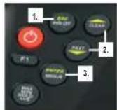
- (ESC) key
- Up and down keys
- (ENTER/MENUE) key
Menu structure
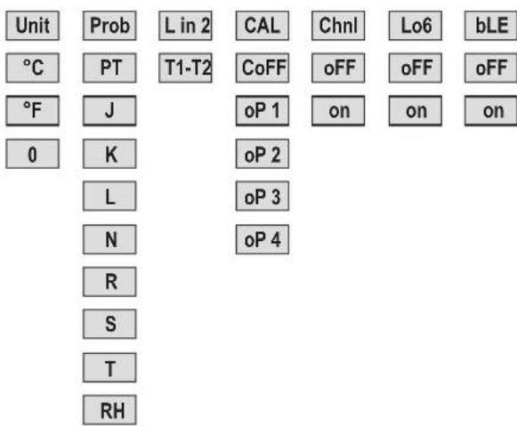
flowchart
graph TD
    A["Unit"] --> B["Prob"]
    B --> C["L in 2"]
    C --> D["CAL"]
    D --> E["Chnl"]
    E --> F["Lo6"]
    F --> G["bLE"]
    H["°C"] --> I["PT"]
    I --> J["T1-T2"]
    J --> K["CoFF"]
    K --> L["oFF"]
    L --> M["oFF"]
    N["°F"] --> O["J"]
    O --> P["oP 1"]
    P --> Q["on"]
    Q --> R["on"]
    S["0"] --> T["K"]
    T --> U["oP 2"]
    U --> V
    W["L"] --> X["oP 3"]
    X --> Y
    Z["N"] --> AA["oP 4"]
    AA --> AB
    AC["R"] --> AD
    AE["S"] --> AF
    AG["T"] --> AH
    AI["RH"] --> AJ
1.4.1 Measuring unit switching °C, °F and Resistance (Ohm's) (Unit) Unit = Measuring unit
Measuring unit temperature (°C=Celsius, °F=Fahrenheit, o=Ohm) To change the measuring unit push (ENTER/MENUE). Use the up and down keys (▲▼) to select Unit. Push again (ENTER/MENUE). On the right corner of the display appears °C, °F or o. Use the up and down keys (▲▼) again to adjust the requested measuring unit and push (ENTER/MENUE) to confirm. Push (ESC) to be back in the measuring mode.

flowchart
graph LR
    A["UN"] --> B["Prob"]
    B --> C["L in 2"]
    C --> D["CAL"]
    D --> E["Chnl"]
    E --> F["Lo6"]
    F --> G["bLE"]
    G --> H["MENUE"]
    H --> I["UN"]
    I --> J["Prob"]
    J --> K["L in 2"]
    K --> L["CAL"]
    L --> M["Chnl"]
    M --> N["Lo6"]
    N --> O["bLE"]
The Instrument detect Smartprobes with Eprom automatically. It is not necessary to select this probes by the menu function Prob! After switching on the displays option CAL 4 (1 sensor with Eprom) or CAL 44 (2 sensors with Eprom).
1.4.3 Probe selection / (Prob)
In case of using probes of the instrument series (P700-P770) please select probes according to the following description. Push (ENTER/MENUE) to change a probe. Use the up and down keys (▲▼) to select Prob. Push (ENTER/MENUE) to confirm.

flowchart
graph LR
    A["MENUE"] --> B["Unit"]
    A --> C["Prob"]
    A --> D["L in 2"]
    A --> E["CAL"]
    A --> F["Chnl"]
    A --> G["Lo6"]
    A --> H["bLE"]
    B --> I
    C --> I
    D --> I
    E --> I
    F --> I
    G --> I
    H --> I
On the left corner of the display appears a small 1, which indicates the selected channel. For changing the channel use the up and down keys (▲▼). Push again (ENTER/MENUE) to confirm. On the right corner of the display appears the active probe. Use the up and down keys (▲▼) to change the probe. Push (ENTER/MENUE) to confirm the requested probe. Push (ESC) to be back in the measuring mode.
| Measurement | Probe selection (Prob) | LC-Display | Suitable for these types of measuring instruments: |
| Temperature | Pt100 (RTD) | Pm | P700/P705/P750/P755/P770/P755-LOG/P770-LOG |
| Temperature | Fe-CuNi Typ J | for all P700-instruments | |
| Temperature | NiCr-Ni Typ K | for all P700-instruments | |
| Temperature | Fe-CuNi Typ L | L | for all P700-instruments |
| Temperature | NiCrSi-NiSi Typ N | N | for all P700-instruments |
| Temperature | Pt13Rh-Pt Typ R | R | P700/P705/P750/P755/P770/P755-LOG/P770-LOG |
| Temperature | Pt10Rh-Pt Typ S | S | P700/P705/P750/P755/P770/P755-LOG/P770-LOG |
| Temperature | Cu-CuNi Typ T | for all P700-instruments | |
| Humidity | %rF | RH | P700/P705/P750/P755/P770/P755-LOG/P770-LOG |
Push (ENTER/MENUE) to confirm. Push (ESC) to revert back to the measuring mode.
Note: Please check the probe selection to be sure that the correct probe is entered. If a measurement value is changed with the ENTER-key at the menu Prob, the standard calibration will be automatically used.
Indications for the combination probes (temperature and humidity):
Please adjust relatively humidity as measurement value for the channel on which the combination probe is plugged. If you want that the measured temperature of the plugged combination probe is shown as well, you have to deactivate the channel on which no probe is plugged on (see chapter 1.4.6./Chnl)
1.4.4 Temperature difference / (L in2)
To display the temperature difference push (ENTER/MENUE). Use the up and down keys (▲▼) to select L in2. Push again (ENTER/MENUE). On the right corner of the display appears a T1-T2. Use the up and down keys (▲▼) to adjust the requested selection. Push (ENTER/MENUE) to confirm. Push (ESC) to revert back to the measuring mode.

flowchart
graph LR
    A["Unit"] --> B["Prob L in 2-6AL ClmL Lo6 b-E"]
    B --> C[" "]
    C --> D[" "]
    D --> E[" "]
    E --> F[" "]
    F --> G["MENUE"]
    G --> A
Note: Both channels have to be activated for displaying temperature difference.
1.4.5 Calibration function / (CAL)
Despite high quality manufacturing techniques, each probe is slightly different from specified standards. To eliminate inaccuracies caused by exchanging or ageing of probes, the instrument offer easy calibration functions which guarantee that the system accuracy is always as good as if the instrument was specifically calibrated to the individual probes in our laboratory.
The instruments offer five different calibration options:
1) (CoFF): Standard characteristic curve
(e.g. Pt100-resistance according EN60751)
2) (oP 1): Calibration by code (2 x four digit code) is equivalent to a 2-point calibration. The code is marked clearly by a label on each standard probe.
3) (oP 2): Calibration by physical standard references
(1-point, 2-point or 3-point calibration)
4) (oP 3): Calibration according to Coefficients of EN60751 (RO, ABC)
5) (oP 4): Smart EEprom probes with internal calibration
CAL = calibration
Push (ENTER/MENUE) to calibrate the instrument with sensor. Use the up and down keys (▲▼) to select CAL. Push again (ENTER/MENUE). On the left corner of the display appears a small 1, which indicates the selected channel. To change the channel (1 or 2) use the up and down keys (▲▼). Push (ENTER/MENUE) to confirm.

flowchart
graph LR
    A["UN"] --> B["Prob L in 2"]
    B --> C["CAL"]
    C --> D["Lo6 b-E"]
    D --> E["Square"]
    E --> F["Square"]
    F --> G["Square"]
    G --> H["MENUE"]
    H --> I["Output"]
Use the up and down keys (▲▼) to select the requested calibration option. Push (ENTER/MENUE) to confirm.

flowchart
graph LR
    A["CAL"] --> B["CoFF"]
    B --> C["1 oP 2"]
    C --> D["3 oP 4"]
    D --> E[" "]
    E --> F[" "]
    F --> G[" "]
    G --> H[" "]
    H --> I[" "]
    I --> J[" "]
    J --> K[" "]
    K --> L[" "]
    L --> M[" "]
    M --> N[" "]
    N --> O[" "]
    O --> P[" "]
    P --> Q[" "]
    Q --> R[" "]
    R --> S[" "]
    S --> T[" "]
    T --> U[" "]
    U --> V[" "]
    V --> W[" "]
    W --> X[" "]
    X --> Y[" "]
    Y --> Z[" "]
    Z --> A
1) Standard calibration according to DIN EN60751 / (CoFF)
Use the up and down keys (▲▼) to select (CoFF). Push (ENTER/MENUE) to confirm. Push (ESC) to revert back to the measuring mode.
2) Calibrationby code / oP1
Use the up and down keys (▲▼) to select oP 1. Push (ENTER/MENUE) to confirm. On the bottom of the display appears a small 1, after this number a four-digit number (Hex-Code/0..F) is displayed. For changing the number use the up key (▲). To step to the next number use the down key (▼). If the requested number is complete then push (ENTER/MENUE) to confirm. At the bottom of the display a very small 2 appears, after which a second four-digit number is displayed. For changing the number please follow the manual as before. Push (ESC) to revert back to the measuring mode.
Note:
After confirming oP 1 by pushing (ENTER/MENUE) the function oP 1 (calibration by code) is activated, even though you leave the menu by pressing (ESC).
Display-indication with active calibration code (oP 1):
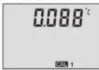
The CAL-segment and the small 1 indicates to the user that oP 1 is activated.
3) Calibration by physical standard references / oP 2
Use the up and down keys (▲▼) to select oP 2. Push (ENTER/MENUE) to confirm. On the bottom of the display appears 1 P. For changing between a 1-Point (1 P), 2-Point (2 P) or 3-Point (3 P) - calibration use the up and down keys (▲▼).
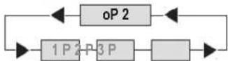
Example of a 1-Point calibration:
Push (ENTER/MENUE) to confirm. On the display appears CALC. After the displayed measuring value is stable push (ENTER/MENUE). On the first display line you can see the "frozen" measure ment value. On the second line as a default you can see -100.000. Now you have to enter (instead of -100.000) the correct measure ment value from your reference:
By using the up key (▲) you are able to move the decimal point to setup the number of decimal places. Push (ENTER/MENUE) to con firm.
Now the algebraic sign is blinking “-”. Use the up key (▲to toggle for positive or negative number. Change the number using the up and down keys (▲▼
(▲is changing the blinking segment
(▼) is jumping to the next segment
Push (ENTER/MENUE) to confirm, revert back to the measuring mode.
Important:
To abort the physical calibration use the (ESC)-button.
Display-indication with active calibration code (oP 2):
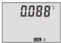
The CAL-segment and the small 2 indicates to the user that oP 2 is activated.
4) Calibration according to Coefficients of EN60751 (R0, ABC)/oP 3
By using Option 3 you are able to activate coefficients according to EN60751 (RO, A, B, C). The coefficients have to be calculated using special software on a PC (e. g. P7_CALC). Before you are able to activate this option you have to transmit the coefficients from the PC to the instrument. Therefore you have to use the Soft ware P7_CALC, too.
Use the up and down keys ( ) to select oP 3. Push (ENTER/MENUE) to confirm. Now the calibration option 3 is activated! Push (ESC) to revert back to the measuring mode.
Note: After confirming oP 3 by pushing (ENTER/MENUE) the function oP 3 (calibration by code) is activated, even though you leave the menu by pressing (ESC).
Display-indication with active calibration code (oP 3):
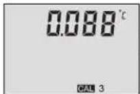
The CAL-segment and the small 3 indicates to the user that oP 3 is activated.
5) Smart EEprom-probes with internal calibration (AUTO-Detection) / oP 4 The Option 4 will be activated automatically by using Smart EEprom probes. This option will be activated by switching on the instrument when the Smart EEprom probe has been connected to the instrument.
Display-indication with active calibration code (oP 4):
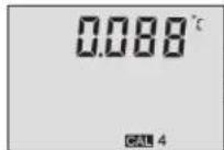
The CAL-segment and the small 4 indicates to the user that oP 4 is activated.
Note:
If a Smart probe will be disconnected during the instrument is working the instrument automatically switch to the CAL-menu.
1.4.6 Channel activation (only 2-channel instruments) / (Chnl) Chnl = Channel
To activate or deactivate a measuring channel push (ENTER/MENUE). Use the up and down keys (▲) to select Chnl. Push again (ENTER/MENUE). On the left corner of the display appears a small 1, which indicates the selected channel. To change the channel use the up and down keys (▲) to push (ENTER/MENUE) to confirm. Use the up and down keys (▲) again to activate on or deactivate off the requested measuring channel and push (ENTER/MENUE) to confirm. Push (ESC) to revert back to the measuring mode.
Note: As a minimum one channel is active!

flowchart
graph LR
    A["UN"] --> B["Prob"]
    B --> C["L in 2"]
    C --> D["CAL"]
    D --> E["Chnl"]
    E --> F["Lo6"]
    F --> G["bLE"]
    G --> H["MENUE"]
    H --> A
1.4.7 Memory Setup Lo6
Push (ENTER/MENUE) and use the up and down keys (▲▼) to select Lo6. Push (ENTER/MENUE) to confirm. Use the up and down keys (▼) again to start (on) or Stop (off) the logger. Push (ENTER/MENUE) to confirm. Use the up and down keys (▲) again to select between automatic storage (Auto) or manually operated storage (SPot). Push (ENTER/MENUE) to confirm. Use the up and down keys (▲▼) again to select between to add on data (Add) and creating a new file (nLo6). Push (ENTER/MENUE) to confirm. By selected automatic storage at the end you have to select the time interval:
| 1 S | 1 second | 1 M | 1 minutes |
| 5 S | 5 second | 2 M | 2 minutes |
| 10 S | 10 second | 5 M | 5 minutes |
| 20 S | 20 second | 10 M | 10 minutes |
| 30 S | 30 second | 20 M | 20 minutes |

flowchart
graph LR
    A["UN"] --> B["Unit"]
    B --> C["Prob"]
    C --> D["L in 2"]
    D --> E["CAL"]
    E --> F["Chnl"]
    F --> G["Lo6"]
    G --> H["bLE"]
    H --> I["MENUE"]
    I --> A
E.g. of the instrument's LCD by activated logging mode:
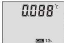
On the bottom you can see the percentage of the occupied memory (0..99%). If a calibration option is activated the display is alternating between displaying memory status and calibration information.
1.4.8 Bluetooth activation/deactivate / (bLE)
bLE = Bluetooth = off / on
To activate or deactivate bluetooth push (ENTER/MENUE). Use the up and down keys (▲▼) to select bLE. Push again (ENTER/MENUE). Use the up key (▲) to activate on or deactivate off the bluetooth function and push (ENTER/MENUE) to confirm. Push (ESC) to revert back to the measuring mode.

flowchart
graph LR
    A["UNITS"] --> B["Preb L in2"]
    B --> C["CAL Chm"]
    C --> D["Lo6 b-E"]
    D --> E["Output"]
    F["MENUE"] --> A
    F --> E
1.5 Recalling the memory data (HOLD MAX MIN AVE)
After pushing first time the key (HOLD MAX MIN AVE) the actual values will be held on the display. Pushing again the key (HOLD MAX MIN AVE), the saved maximum-, minimum and average values will be displayed.
Note: During the recall of the memory data the extremes (MAX MIN) and the average value (AVE) will not be calculated or carried on.
Clearing the memory (MAX MIN AVE)
Press (CLEAR) key once to erase the stored maximum, minimum and average from memory. On the display appears Clr. – After erasing the memory the instrument automatically reverts back to measuring mode indicating the actual measured value again.
The instrument has three different response times to select:
Normal-Mode: high resolution
(0.001 from -199.999 to +199.999)
FAST-Mode: reduced resolution
(0.01 from -199.99 to +199.99)
Filter-Mode: high resolution
(0.001 from -199.999 to +199.999)
Press (FAST / ▼) key to change the measuring rate. By using the Filter-Mode the instrument is performing a moving average to stabilize the dispayed measurements. After turning on the instrument it is in the Normal-Mode. After pressing once the (FAST / ▼) key the instrument switches to the Fast-Mode. Pressing the same key once again the instrument switches to the Filter-Mode.
E.g. Display with activated Filter-Mode:
0.088
The arrow on the top indicates that the instrument is working in the Filter-Mode.
Note: After switching off the instrument, this function is automatically deactivated.
1.7 AUTO-OFF-function
dAoF = Disable Auto-off
EAoF = Enable Auto-off
Press (ESC/AUTO-OFF) key once. On the display appears EAoF. Now the instrument switches off automatically after app. 30 minutes. Press (ESC/AUTO-OFF) key again. On the display appears dAoF. Now the Auto-Off-function is deactivated.
Attention: This setting will be deactivated when the instrument turns off. (Standard setting is EAoF).
1.8 TARE-Function (ZERO-Mode F1)
The Instrument has a special Tare/Zero-button. Pressing the (F1) key once, the instrument will subtract the last measured value from the actual measured value. So if the measurement does not change zero appears on the instrument's display. If you press the (F1) key once again the instrument move to the Normal-Mode.
E.g. Display with activated Zero-Mode:
0.088°
The arrow on the left indicates that the instrument is working in the Zero-Mode (F1).
Note: After switching off the instrument, this function is automatically deactivated.
2. Power supply
- For the power supply of the instrument a 9 Volt dry battery is used. To exchange the battery switch of the instrument and open the rear battery cover. Remove the battery from the instrument and replace with a new battery.
- The "BAT" symbol in the display indicates that the battery needs to be exchanged. After displaying the "BAT" symbol, the instrument allows app. 1 hour of further operation.
- The battery symbol indicates according to the battery status between 1 to 3 segments.
Attention:
Please do not dispose of old electronic devices and empty batteries in household waste. To protect the environment, take them to your retail store or to appropriate collection sites according to national or local regulations.
3. Error Codes
By displaying the following error codes the instrument support the operation of the instrument:
Error Meaning
oPEn no probe or wrong probe is connected
"toorow" underflow of the measuring range
Too high" exceeding of the measuring range
E15 low battery (battery is completely exhausted)
E19 low battery (battery is completely exhausted)
E1d low battery (battery is completely exhausted)
E16 time out / auto-off-function (Switch device on again)
E1e time out / auto-off-function (Switch device on again)
E23 RAM content destroyed (check settings)
E25 EE-prom destroyed or EE-prom index is wrong
E31 Interface error
LoLi internal buffer battery (CR2032) empty (for changing the battery the housing must be unscrewed)
Hinweis:
Hint: Defective or empty batteries can cause measurement errors or error messages. On error messages, remove battery and wait 3 minutes prior to mounting a new battery.
Table des matières
text_image
Unit °C °F 0 L N R S T RH Prob PT J K L R T1-T2 CAL CoFF oP 1 oP 2 oP 3 oP 4 Chnl oFF on on Lo6 oFF on bLE oFFbLE = Bluetooth = off / on