BST 250 - Drill Baier - Free user manual and instructions
Find the device manual for free BST 250 Baier in PDF.

User questions about BST 250 Baier
0 question about this device. Answer the ones you know or ask your own.
Ask a new question about this device
Download the instructions for your Drill in PDF format for free! Find your manual BST 250 - Baier and take your electronic device back in hand. On this page are published all the documents necessary for the use of your device. BST 250 by Baier.
USER MANUAL BST 250 Baier
natural_image
Mechanical device with vertical shaft and lever mechanism (no visible text or symbols)Translation of the Original Instruction Manual
Drill stand BST 200-250
text_image
Technical diagram of a mechanical device with numbered parts and cross-sectional views labeled (4x)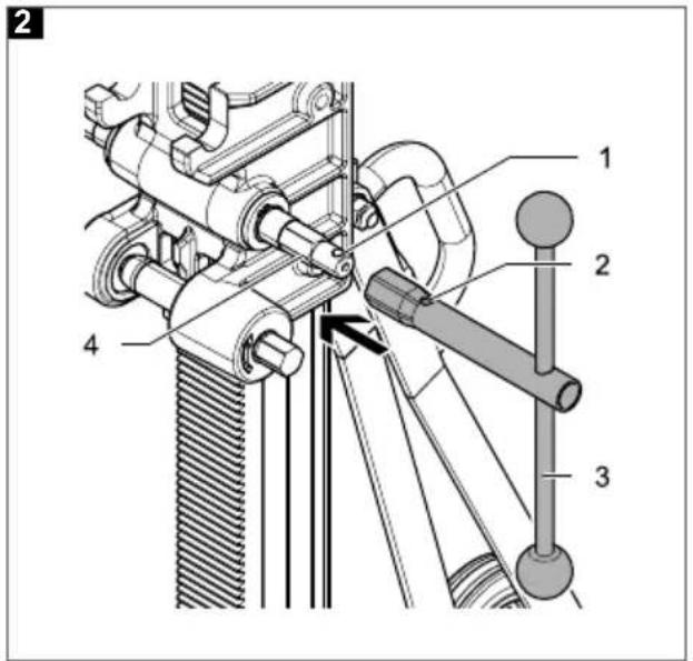
text_image
Technical diagram of a mechanical device with numbered components and directional arrow indicating motion or force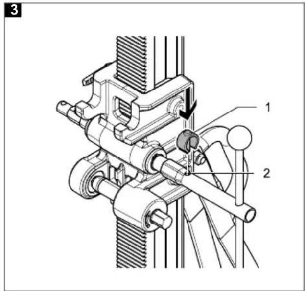
text_image
Technical diagram of a mechanical device with labeled parts 1 and 2, showing assembly or assembly details.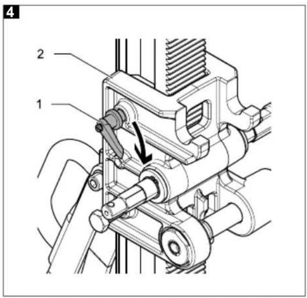
text_image
4 1 2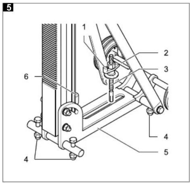
text_image
5 1 2 3 4 5 6 4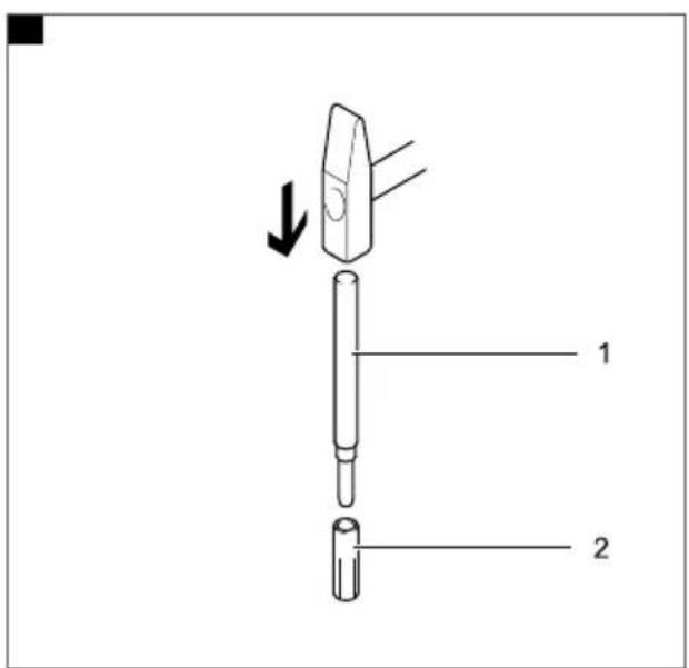
text_image
Diagram of a pen-like tool with labeled parts and directional arrow indicating movement or assembly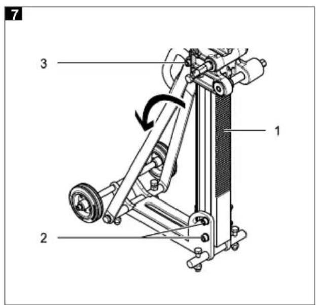
text_image
7 3 1 2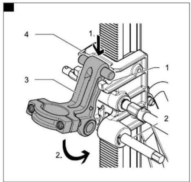
text_image
Technical diagram of a mechanical device with numbered components and rotational motion indicators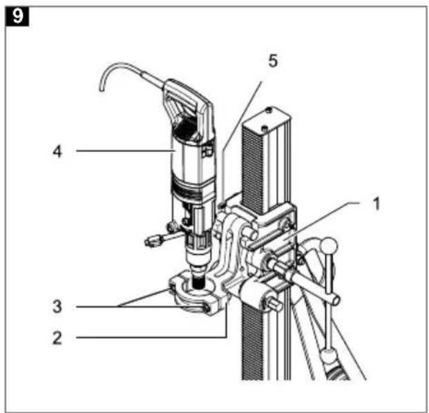
text_image
9 4 3 2 5 1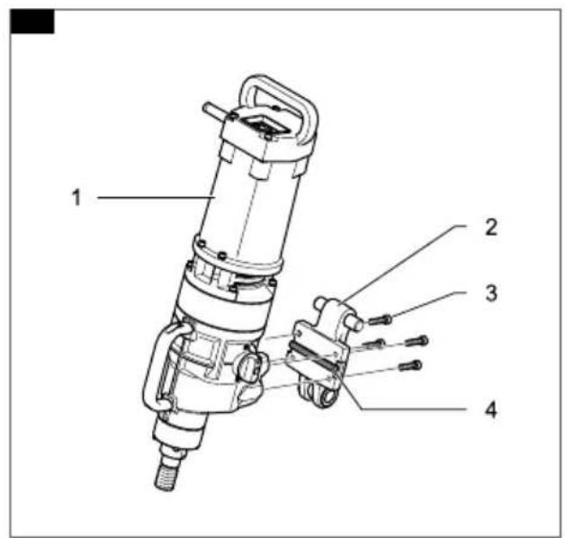
text_image
1 2 3 4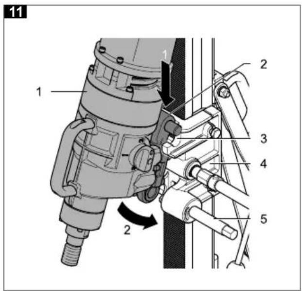
text_image
11 1 2 2 3 4 5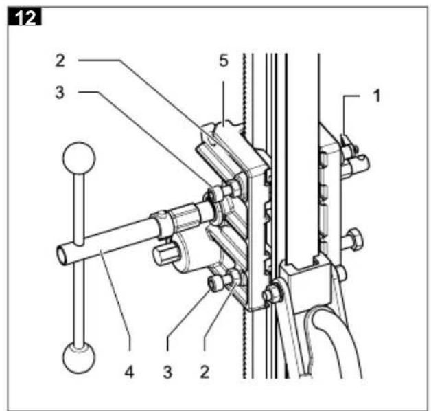
text_image
12 2 3 5 1 4 3 2Impressum
Version V01/2019-03
Copyright:
Maschinenfabrik
OTTOBAIERGmbH
Heckenwiesen 26
71679 Asperg
Deutschland
It is prohibited to forward or reproduce this document or to exploit and disclose its contents, unless expressly permitted. Any infringements will result in liability to pay compensation for damages. All rights reserved in case of patent, utility model or design registration.
This instruction manual has been prepared with the greatest possible care. Nonetheless, OTTO
BAIER GmbH does not accept any liability whatsoever for possible errors in this instruction manual and their consequences. Equally, no liability whatsoever is accepted for direct or consequential damage or losses resulting from improper use of the machine.
The national health and safety regulations and the requirements of this instruction manual are to be observed when using the machine.
All product names and brand names used are the property of the holder and are not explicitly marked as such.
Subject to change without notice.
Contents
1 About this instruction manual ..... 18
1.1 Important information 18
1.2 Symbols used in the instruction manual 18
2 Safety Instructions 19
2.1 Operating personnel requirements ..... 19
2.2 Workplace safety 19
2.3 Electrical safety 19
2.4 Safety of people 19
2.5 Using and handling the drill stand ..... 19
2.5.1 Service / Maintenance / Repair 21
2.5.2 Explanation of the pictograms on the drill stand 21
3 Technical Characteristics 22
3.1 Technical specifications, drill stands ..... 22
3.2 EC Declaration of Conformity 22
3.3 Controls 22
3.4 Intended use 23
4 Before starting work 23
5 Operation and Control 23
5.1 Installing the drill rig with plug fixing ..... 23
5.2 Fixing onto the wall 23
5.3 Installing the drill stand with vacuum kit (accessory) 23
5.4 Adjusting the tilt at the drill stand 24
5.5 Fixing the diamond drill / drive unit to the BST 200 drill stand 24
5.6 Fixing the diamond drill / drive unit to the BST 250 drill stand 24
5.7 Work instructions 24
6 Cleaning 25
7 Maintenance 25
7.1 Setting guide clearance on the spindle head 25
8 Tools and Accessories 26
9 Disposal 26
10 Scope of Supply 26
11 Warranty 27
1 About this instruction manual
This instruction manual contains all important information necessary for safe handling of the drill stand.
The drill stand is also referred to as the "tool" in this instruction manual.
Figure references
References to figures, which are located at the beginning of the instruction manual are displayed in the text with this symbol 1 (here, for example, the reference is to Figure number 1).
1.1 Important information

Read the instruction manual
Before starting any work with or on the tool, this instruction manual, the safety instructions and the warnings must be read through carefully and observed.
Always keep this instruction manual together with the equipment.

An approved half-mask with filter must be worn!
1.2 Symbols used in the instruction manual

DANGER
"DANGER" indicates an imminent hazard, which will result in immediate death or severe physical injuries.
→ This arrow indicates appropriate measures to avert the pending hazard.

WARNING
"WARNING" indicates an imminent hazard, which could result in death or severe physical injuries.
→ This arrow indicates appropriate measures to avert the pending hazard.

CAUTION
"CAUTION" indicates an imminent hazard, which can result in minor or moderate physical injuries.
→ This arrow indicates appropriate measures to avert the pending hazard.

NOTE
"NOTE" indicates possible property damage, gives use recommendations and helpful tips.
2 Safety Instructions

WARNING
Read all safety information and instructions supplied with the drill stand and drill or drive units. Failure to observe the safety instructions and precautions can cause serious injuries.
You must always comply with the currently valid version of the general accident prevention / health & safety regulations.
Keep all safety instructions and precautions for future reference.
2.1 Operating personnel requirements
a) People below the age of 18 may not use the unit.
b) Store drill stands out of the reach of children when not in use. Do not allow people to use the tool unless they are familiar with it, or if they have not read this instruction manual.
Drill stands are dangerous if they are used by inexperienced people.
c) Always work carefully, attentively and sensibly when using this tool. Do not use the unit if you are tired or are under the influence of drugs, alcohol or medication.
A moment of inattention while using the tool can result in serious injuries.
2.2 Workplace safety
a) Keep your work area clean and well illuminated.
Untidiness and unlit work areas can result in accidents.
b) Watch out for open and concealed electricity cables, and water and gas pipes. Use suitable detectors to find concealed utility pipes and cables, or contact the local utility company for advice.
Contact with electricity cables can cause fires and an electric shock. Damage to a gas pipe can cause an explosion. Penetrating a water pipe causes damage to property or could cause an electric shock.
c) Inform and consult the responsible structural engineer, architect or the responsible site engineer about planned drilling.
Cut through reinforcement only with the approval of a structural engineer.
2.3 Electrical safety
a) Before use, check all water-carrying parts – including those of the accessories – for perfect working order and leaks.
Leaking water increases the risk of an electric shock.
2.4 Safety of people
a) Wear personal protective equipment and always wear goggles.
The wearing of personal protective equipment, such as dust mask, non-slip safety shoes, helmet or ear protectors, depending on the type and application of the power tools, reduces the risk of injuries.
b) Avoid abnormal postures when working. Ensure you are standing firmly and maintain your balance at all times.
This will enable you to control the tool better in unexpected situations.
c) Wear suitable clothing. Do not wear loose clothing or jewellery. Keep your hair, clothing and gloves away from moving parts.
Loose clothing, jewellery and long hair can get caught in moving parts.
d) If dust extraction and collection devices can be installed, ensure that these are connected and are used correctly.
Use of a dust/water extraction system can reduce hazards caused by dust.
e) Don't be lulled into a false sense of safety and do not break the safety rules for drill stands even if, after much use, you are familiar with the drill stand.
Careless action can cause severe injuries within fractions of a second.
f) When carrying out drilling work that requires the use of water, route the water away from the work area or use a liquid collection device.
Such precautions keep the work area dry and reduce the risk of an electric shock.
2.5 Using and handling the drill stand
a) Before mounting the drill or drive unit, set up the drill stand correctly in accordance with these instructions. Correct assembly is important to ensure proper, faultless functioning of the stand.
EN
b) Fasten the drill stand securely on a firm, flat surface using the specified and undamaged installation materials.
If the drill stand can slip or wobble, the drill or drive unit cannot be guided uniformly and safely.
c) Disconnect the plug of the drill or drive unit from the socket before mounting the drill or drive unit on the drill stand, make any unit settings or change accessory parts.
Unintentional starting of drills or drive units causes accidents.
d) Fix the drill or drive unit securely onto the drill stand as specified before starting work.
Slipping of the drill or drive unit on the drill stand can cause loss of control and injuries.
e) Remove all setting tools, spanners and installation materials not required before switching on the drill or drive unit.
Setting tools, spanners and installation materials located in/on a rotating part of the tool can result in injuries.
f) Do not overload the drill stand and do not use it as a ladder or scaffolding.
Overloading or standing on the drill stand can cause the centre of gravity of the drill stand to move upwards and the drill stand overturns.
g) Keep the handles and gripping surfaces dry, clean and free from oil and grease.
Slippery handles and gripping surfaces prevent safe operation and control of the drill stand in unforeseen situations.
h) When fixing the drill stand on the workpiece using anchors and screws, ensure that the anchoring used is able to hold the machine safely during use.
If the workpiece is not resistant or is porous, the anchor can be pulled out, which causes the drill stand to detach from the workpiece.
i) If fixing the drill stand on the workpiece by means of a vacuum plate, ensure that the surface is smooth, clean and not porous.
Do not fix the drill stand onto laminated surfaces, such as tiles and facings of composite materials.
If the surface of the workpiece is not smooth, flat or adequately fixed, the vacuum plate can detach from the workpiece.

NOTE
The above safety instruction only applies if it is planned to use the tool with a vacuum plate.
j) Before and while drilling, ensure that the vacuum is sufficient.
If the vacuum is insufficient, the vacuum plate can detach from the workpiece.

NOTE
The above safety instruction only applies if it is planned to use the tool with a vacuum plate.
k) Never carry out overhead drilling and drilling, if the drill stand is fixed on the machine by means of a vacuum plate only.
In the event of loss of vacuum, the vacuum plate detaches from the workpiece.

NOTE
The above safety instruction only applies if it is planned to use the tool with a vacuum plate.
Use RAWL anchors with diameter 20 mm / M12 for fixing onto walls.
I) Do not use any accessories that have not been especially provided and recommended for this drill stand by the manufacturer.
Just because you can attach accessories to your drill stand is not a guarantee of safe use.
m) Additional signs or other, non-BAIER-specific parts must not be screwed or riveted onto the drill stand.
This could damage the drill stand and cause malfunctions to occur.
n) Note and follow all safety and work instructions for the accessories used.
o) Never place the feed crank handle on the hexagon of the tapered shaft to tighten it.
Excessive torques could damage it.
2.5.1 Service / Maintenance / Repair
a) Maintain the unit with care in accordance with the stipulations of the instruction manual. Check whether moving unit parts are in proper working order and do not jam, whether parts are broken or damaged in such a way that they impair the function of the unit.
Many accidents are caused by poorly maintained tools and accessories.
b) Repair and maintenance work may only be carried out by an authorised service centre of OTTO BAIER GmbH. Otherwise, all liability and warranty claims against OTTO BAIER GmbH expire.
c) Ensure that original BAIER spare parts and original BAIER accessories only are used when needed.
Original parts are available from authorised dealers. Use of non original parts can cause damage to the machine and an increased risk of accidents.
2.5.2 Explanation of the pictograms on the drill stand

The CE mark on a product means that the product conforms with all the applicable European regulations and has been subjected to the prescribed conformity assessment procedures.

Wear heating protection!
Do not dispose of tool in household waste. Waste equipment contains valuable recyclable materials which should be reused or recycled. Batteries, lubricants and similar materials must not be allowed to get into the environment. Therefore, please dispose of waste equipment through suitable collection systems.

Read the instruction manual! Before starting any work with or on the equipment, this instruction manual, the safety instructions and the warnings must be read through carefully and observed.
3 Technical Characteristics
3.1 Technical specifications, drill stands
| Drill stand BST 200 BST 250 | ||
| Manufacturer Maschinenfabrik OTTO BAIER GmbH | ||
| Maximum drilling stroke (mm) 570 570 | ||
| Maximum diameter drilled (mm) 200 250 | ||
| Height (mm) 900 900 | ||
| Width (mm) 320 320 | ||
| Depth (mm) 600 850 | ||
| Weight (kg) 15.5 15.4 | ||
| Fastening drive unit/drill to the spindle head via the motor collar | Yes | - |
| Fastening drive unit /drill to the spindle head via the mounting plate | - | Yes |
3.2 EC Declaration of Conformity
CE
We confirm with sole responsibility that these products comply with provisions of the Directives:
2006/42/EC (Machinery Directive) 2011/65/EU (RoHS Directive)
in conjunction with the safety instructions documented in the instruction manual and the specified intended use.
The head of development is authorised to write the technical documents.
These are available from:
Maschinenfabrik OTTO BAIER GmbH, Heckenwiesen 26, 71679 Asperg Germany

Thomas Schwab Managing Director

Robert Pichl Factory Manager
Asperg, 05.12.2018
3.3 Controls
1 BST 200 and BST 250 drill stands
1 Sliding element
2 Nut, top tilt adjustment
3 Pinion shaft
4 Tube lock with clip
5 Feed crank handle
6 Tapered shaft
7 Spirit level
8 Drill stand plate
9 Nut, bottom tilt adjustment
10 Adjustable foot (4x)
11 Cheese head screws, bottom tilt adjustment
12 Cheese head screws, machine collar (BST 200 only)
13 Machine collar (BST 200 only)
14 Bolt-on plate (BST 250 only)
15 Cheese head screw (4x) (BST 250 only)
16 Circlip
17 Spindle head
18 Hexagon bolt
19 Clamping lever
20 Drill stand column
3.4 Intended use
The drill stand is intended for holding diamond drills with a maximum power of 2.2 kW in conjunction with wet diamond drill bits and a water supply for wet drilling in mineral materials such as concrete, reinforced concrete or masonry. The largest allowable diameter drilled is 200 mm for the BST 200 and 250 mm for the BST 250. Other units, which exceed these values, may not be used. The drill stand can be attached to the floor and to the wall with the help of plugs / anchors or vacuum.

NOTE
Use RAWL anchors with diameter 20 mm / M12 for fixing onto walls.
Observe the relevant regulations in your country for the materials to be machined and extraction.
4 Before starting work
To ensure safe working with the drill stand, the following points must be observed before each use:
- Read through all safety instructions and hazard information in this instruction manual and in the instruction manual of the drive unit / drill used.
- Wear protective clothing such as hard hat, face protection or safety goggles, safety gloves and if necessary an apron.
- Before each use, check the fastening of the drill stand.
- Check that the drive unit / drill sits securely in the drill stand.
• 2/3 Mounting the feed crank handle:
2 Push the feed crank handle (3), as required, to the left or right onto the pinion shaft (4) so that the drillhole in the feed crank handle (2) and in the pinion shaft (1) coincide.
3 Push the pin of the tube lock (1) through the matching holes (2) and push until the clip is snapped into position.
• 4 Blocking the feed:
By pulling the clamping lever (1) the spindle head (2) can be clamped and therefore protect the feeding device from unexpected movements.
5 Operation and Control
The drill stand can be fixed onto the floor or wall using a retaining screw.
5.1 Installing the drill rig with plug fixing
5 Use the diamond core drill bit to align the drill stand with the hole to be drilled:
- 5 Mark the plug hole for fixing the drill stand plate (5) through the mounting slot and drill (drill hole: ∅ 15 mm, depth 50 mm).
- 6 Insert the retaining screw (1) with attached quick-action plug (2) in the plug hole.
- 5 Align the drill stand plate (5) with the help of the spirit level (6) and the four adjustable feet (4).
- 5 Screw in the retaining screw (3) with the help of the spike (2).
• 5 Tighten the quick-action nut (1) with light hammer blows.
5.2 Fixing onto the wall

NOTE
Use RAWL anchors with diameter 20 mm / M12 for fixing onto walls.
1 If fixing onto the wall, an external spirit level must be used to adjust the perpendicularity of the drill stand with the drillhole of the diamond drill core bit. This adjustment cannot be made using the integrated spirit level (7) on the drill stand.
5.3 Installing the drill stand with vacuum kit (accessory)
If it is not possible to install the drill stand with the anchor fixing, the drill stand can be fixed to the floor or wall using a vacuum kit (order on request). The installation of the vacuum kit is described in the relevant installation instructions.
5.4 Adjusting the tilt at the drill stand
The drill stand can be continuously adjusted up to an tilt of 45^ .
- 7 Undo the top cheese head screw (3) and the two bottom cheese head screws (2) of the angle adjustment, it may be necessary to hold the nuts on the opposite side to prevent them from moving.
- 7 Set the drill stand column (1) to the required drilling angle.
- 7 Re-tighten the two bottom cheese head screws (2) and the top cheese head screw (3).

NOTE
7 The drill stand may not be used again until all three cheese head screws (2 and 3) have been screwed tight.
5.5 Fixing the diamond drill / drive unit to the BST 200 drill stand

NOTE
Ensure that the drill stand is securely in position and stable!
• 4 Use the clamping lever (1) to lock the spindle head (2).
- 8 Unscrew the tapered shaft (2) and pull it out of the spindle head (4) up to the limit stop.
- 8 Hook the machine collar (3) from above into the holder of the spindle head (1) and push the machine collar (3) downwards.
- 8 Push the tapered shaft (2) through the machine collar (3) and tighten using an open-ended spanner.

NOTE
Never use the feed crank handle to tighten the tapered shaft; it could be damaged by excessive torque.
- 9 Undo the two cheese head screw (3) in the machine collar (2).
- 9 Insert the drill (4) from above into the machine collar (2) of the drill stand up to the limit stop.
• 9 Re-tighten the cheese head screws (3). - Repeat in the reverse order to remove the diamond drill.
5.6 Fixing the diamond drill / drive unit to the BST 250 drill stand

NOTE
Ensure that the drill stand is securely in position and stable!
- 10 Insert the feather key (4) in the groove of the bolt-on plate (2).
- 10 Use the 4 retaining screws (3) to screw the diamond drill / drive unit (1) onto the bolt-on plate (2).
• 4 Use the clamping lever (1) to lock the spindle head (2).
• 11 Unscrew the tapered shaft (5) and pull it out of the spindle head (4) up to the limit stop. - 11 Hook the bolt-on plate (2) with the drill (1) from above into the holder of the spindle head (3) and push the bolt-on plate (2) towards the rear.
- Push the tapered shaft (5) through the bolt-on plate (2) and tighten using an open-ended spanner.

NOTE
Never use the feed crank handle to tighten the tapered shaft; it could be damaged by excessive torque.
5.7 Work instructions
- 4 Undo the clamping lever (1) to release the spindle head (2).
• 1 Turn the feed crank handle (5) to guide the drill downwards. - Carefully spot drill the material with the drill bit.
- 1 When the drill bit has drilled several millimetres into the material, the pressure on the feed crank handle (5) can be increased.

NOTE
Use sufficient water during drilling.
6 Cleaning

CAUTION
Risk of injuries due to hot or sharp-edged drill bit.
→ Wear safety gloves.
→ Before carrying out any cleaning work on the drill stand remove the drill bit and wet diamond drill first.
The drill stand must be cleaned after each drilling work session.
- 1 Rub down the toothing and the guide on the drill stand column (20) carefully and use compressed air to remove the drill dust; the guide and toothing must not become smeared.
• 1 Clean the toothing of the pinion shaft (3). - 1 Dismantle the pin of the tube lock (4) on the pinion shaft (3) and pull the pinion shaft 3) out of the spindle head (17). Rub down the toothing of the pinion shaft (3) and use compressed air to remove the drill dust. Push the pinion shaft (3) back into the spindle head (17) up to the limit stop.
- Push the pin of the tube lock (1) through the matching holes (2) and push until the clip is snapped into position.
- 8 Clean and lightly grease the thread of the tapered shaft (2). To do this, use an open-ended spanner to unscrew the tapered shaft (2). Pull out the tapered shaft (2) up to the limit stop. Swing the machine collar (3) upwards and remove from the spindle head (4) from above. The thread of the tapered shaft (2) can now be cleaned and greased. Re-install the tapered shaft in the reverse order.
- Ensure handles are dry and free from grease.

NOTE
Never use the feed crank handle to tighten the tapered shaft; it could be damaged by excessive torque.
Use an open-ended spanner only to tighten the tapered shaft.
7 Maintenance
7.1 Setting guide clearance on the spindle head

CAUTION
Risk of injuries due to hot or sharp-edged drill bit.
→ Wear safety gloves.
→ Before carrying out any cleaning work on the drill stand remove the drill bit and wet diamond drill first.
To achieve good drilling results and lengthen the life of the drill stand, the guide clearance should be re-adjusted after approx. 100 drilling operations. The spindle head must move without any clearance. The clearance is adjusted using two hexagon socket head screws.
• 12 Release the clamping lever (1).
• 12 Undo both lock nuts (2).
• 12 Adjust both hexagon socket head screws (3) until the clearance is removed.
• 12 Tighten both lock nuts (2).
• 12 Turn the capstan handle (4) in both directions and check whether the spindle head (4) moves without clearance.

NOTE
The clearance is set correctly if, when the clamping lever is released, the spindle head with the mounted diamond drill / drive unit does not move downward under its own weight or if so, moves very slowly.
8 Tools and Accessories
• BAIER vacuum kit for drill stand BST 200-250 (on request)
• BAIER water extraction kit for drill stand BST 200-250 (on request)
• BAIER vacuum pump with 10 m suction hose (Id. No. 46771)
- BAIER heavy-duty anchor M12 ∅ 16 mm (Id. No. 6587)
• BAIER setting tool for heavy-duty anchors (Id. No. 7456)
• BAIER quick-release threaded rod, complete M12 (Id. No. 52126)
9 Disposal

Recycle the machine and its packaging in an environmentally friendly way in accordance with the provisions applicable in your country.
10 Scope of Supply
Please refer to the enclosed delivery note for the individual scope of supply of a customer-specific order.
Please refer to the table below for the scope of supply of basic models. Please contact your dealer if parts are missing or damaged.
| Drill stand ID. No. Drill stand | Mounting plate for diamond drill / drive unit on spindle head | Motor collar for diamond drill / drive unit on spindle head | |
| BST 200 8167 x – x | |||
| BST 250 8168 x x – |
x included in scope of supply
11 Warranty
The products placed on the market and distributed by Maschinenfabrik OTTO BAIER GmbH take into account the regulations of the laws concerning engineering tools and equipment to protect against risks to health and safety.
We guarantee the perfect quality of our products and accept the costs of subsequent repairs by replacing the damaged parts or replacement with a new tool in case of design, material and/or manufacturing errors within the warranty period. The warranty period for commercial use is 12 months.
The following are prerequisite for a warranty claim due to design, material and/or manufacturing errors:
1. Proof of purchase and compliance with the instruction manual
A mechanically produced original copy of a purchase voucher must always be submitted in order to make a warranty claim. It must contain the complete address, date of purchase and type designation of the product.
The instruction manual for the respective machine and the safety instructions must have been complied with.
Damage due to faulty operation cannot be recognised as a warranty claim.
2. Correct deployment of the machine
Maschinenfabrik OTTO BAIER GmbH's products are developed and produced for specific purposes.
A warranty claim cannot be acknowledged in the event of failure to comply with the intended use in accordance with the instruction manual, misuse or use for another purpose or use of unsuitable accessories. The warranty does not apply if the machine is deployed in continuous and piece-work operation or for rental and hire purposes.
3. Compliance with servicing intervals
Regular servicing by us or a servicing and repair firm authorised by us is prerequisite for warranty claims. Servicing is specified for when the carbon brushes are worn, however at least once a year.
The machine must be cleaned in accordance with the provisions of the instruction manual.
All warranty entitlements expire in case of intervention/tampering with the machine by third parties (opening the machine).
Servicing and cleaning work are not generally covered by the warranty.
4. Use of original BAIER spare parts
Ensure that original BAIER spare parts and BAIER accessories only are used. They are available from authorised dealers. The type and quantity of grease are to be used according to the valid grease list. Use of non original parts can cause consequential damage to the machine and an increased risk of accidents. Dismantled, partly dismantled machines and machines repaired with third party spare parts are excluded from the warranty.
5. Wearing parts
Certain components are subject to use-induced wear or normal wear and tear caused by use of the respective power tool. These components include, among other things, carbon brushes, ball bearings, switches, power cords, seals, shaft sealing rings. Wearing parts are not covered by the warranty.