
LBE 125 18.0-EC - Grinder Flex - Free user manual and instructions
Find the device manual for free LBE 125 18.0-EC Flex in PDF.

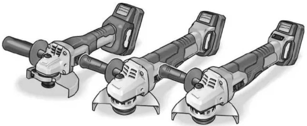
| Product type | Cordless angle grinder |
| Brand | Flex |
| Model | LBE 125 18.0-EC |
| Rated voltage | 18 V |
| Battery type | Lithium-ion (Li-ion) |
| Compatible battery capacities | 2.5 Ah, 5.0 Ah, 8.0 Ah |
| Maximum tool diameter | 125 mm |
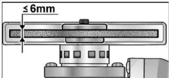
| Tool thickness | 1 to 6 mm |
| Bore | 22.23 mm |
| Spindle thread | M14 |
| No-load speed (adjustable) | 3500 / 4500 / 6500 / 9000 rpm (4 levels) |
| Weight (without battery) | 1.85 kg |
| Sound pressure level (LpA) | 84 dB(A) |
| Sound power level (LWA) | 95 dB(A) |
| Vibration (grinding) | 4.9 m/s² (uncertainty K=1.5 m/s²) |
| Vibration (cutting) | 2.8 m/s² (uncertainty K=1.5 m/s²) |
| Protective guard | Tool-free adjustable, 12 positions over 360° |
| Auxiliary handle | Mountable left or right |
| Switch | Rocker switch with lock-on |
| Electronic speed control | Yes (LBE model) |
| Functions | Grinding, cutting, sanding, wire brushing |
| Integrated protections | Against overloads and overheating |
| Maintenance | Regular cleaning of ventilation slots and dust filter |
| Included accessories | Pin wrench, protective guard, handle |
| Compliance standards | EN 60745, directives 2014/30/EU, 2006/42/EC, 2011/65/EU |
Frequently Asked Questions - LBE 125 18.0-EC Flex
User questions about LBE 125 18.0-EC Flex
0 question about this device. Answer the ones you know or ask your own.
Ask a new question about this device
Download the instructions for your Grinder in PDF format for free! Find your manual LBE 125 18.0-EC - Flex and take your electronic device back in hand. On this page are published all the documents necessary for the use of your device. LBE 125 18.0-EC by Flex.
USER MANUAL LBE 125 18.0-EC Flex
LBE 125 18.0-EC LB 125 18.0-EC L 125 18.0-EC-LD
natural_image
Illustration of four different types of electric drill motors with no visible text or symbolsnatural_image
Close-up of a power tool with a knob and handle, showing mechanical components (no text or symbols visible)i HINWEIS
natural_image
Close-up of a mechanical component with directional arrows indicating movement or flow (no text or symbols)natural_image
Close-up of a camera lens control panel with buttons and an arrow pointing to the button (no text or symbols visible)VORSICHT!
natural_image
Illustration of hands using a cutting tool to cut a metal block, showing angular motion (no text or symbols)natural_image
Two-panel diagram showing mechanical components with arrows indicating rotational or flow direction (no text or symbols)Peter Lameli Technical Head
Klaus Peter Weinper Head of Quality Department (QD)
15.12.2020
Symbols used in this manual ..... 17
Symbols on the power tool 17
For your safety 17
Noise and vibration 21
Technical data 22
Overview 23
Instructions for use 24
Maintenance and care 27
Disposal information 28
C€ Declaration of Conformity ..... 28
UK CA Declaration of Conformity ..... 28
Exemption from liability 29
Symbols used in this manual

WARNING!
Denotes impending danger. Non-observance of this warning may result in death or extremely severe injuries.

CAUTION!
Denotes a possibly dangerous situation. Non-observance of this warning may result in slight injury or damage to property.

NOTE
Denotes application tips and important information.
Symbols on the power tool

Before switching on the power tool, read the operating manual!

Wear goggles!

Wear ear protection!
Disposal information for the old machine (see page 28)
For your safety

WARNING!
Before using the angle grinder, please read and follow:
– these operating instructions,
- the "General safety instructions" on the handling of power tools in the enclosed booklet (leaflet-no.: 315.915),
– the currently valid site rules and the regulations for the prevention of accidents.
This angle grinder is state of the art and has been constructed in accordance with the acknowledged safety regulations.
Nevertheless, when in use, the power tool may be a danger to life and limb of the user or a third party, or the power tool or other property may be damaged. The angle grinder may be operated only if it is
- as intended,
– in perfect working order.
Faults which impair safety must be repaired immediately.
Intended use
This angle grinder
– for commercial use in industry and trade,
- For dry grinding and cutting metal and stone; a special protective hood is required for cutting,
– for grinding surfaces, for derusting and stripping paint when used with the elastic sanding pad (only LBE 125 18.0-EC),
– for drilling in stone material with diamond bits without using water,
– for use with grinding tool, wire brushes and accessories recommended in these instructions or by the manufacturer.
Not permissible are e.g. grinder chainsaw discs, saw blades and (only L 125 18.0-EC LD) diamond-coated grinding discs.
Safety Warnings for Angle Grinder

WARNING!
Read all safety warnings and all instructions. Failure to follow the warnings and instructions may result in electric shock, fire and/or serious injury. Save all warnings and instructions for future reference.
Safety Warnings Common for Grinding, Sanding, Wire Brushing or Abrasive Cutting-Off Operations
■ This power tool is intended to function as a grinder, sander, wire brush or cut-off tool. Read all safety warnings, instructions, illustrations and specifications provided with this power tool. Failure to follow all instructions listed below may result in electric shock, fire and/or serious injury.
■ Operation such as polishing is not recommended to be performed with this power tool. Operations for which the power tool was not designed may create a hazard and cause personal injury.
■ Do not use accessories which are not specifically designed and recommended by the tool manufacturer. Just because the accessory can be attached to your power tool, it does not assure safe operation.
■ The rated speed of the accessory must be at least equal to the maximum speed marked on the power tool. Accessories running faster than their rated speed can break and fly apart.
■ The outside diameter and the thickness of your accessory must be within the capacity rating of your power tool. Incorrectly sized accessories cannot be adequately guarded or controlled.
- Threaded mounting of accessories must match the grinder spindle thread. For accessories mounted by flanges, the arbour hole of the accessory must fit the locating diameter of the flange. Accessories that do not match the mounting hardware of the power tool will run out of balance, vibrate excessively and may cause loss of control.
■ Do not use a damaged accessory. Before each use inspect the accessory such as abrasive wheels for chips and cracks,
backing pad for cracks, tear or excess wear, wire brush for loose or cracked wires. If power tool or accessory is dropped, inspect for damage or install an undamaged accessory. After inspecting and installing an accessory, position yourself and bystanders away from the plane of the rotating accessory and run the power tool at maximum no-load speed for one minute. Damaged accessories will normally break apart during this test time.
■ Wear personal protective equipment. Depending on application, use face shield, safety goggles or safety glasses. As appropriate, wear dust mask, hearing protectors, gloves and workshop apron capable of stopping small abrasive or workpiece fragments. The eye protection must be capable of stopping flying debris generated by various operations. The dust mask or respirator must be capable of filtrating particles generated by your operation. Prolonged exposure to high intensity noise may cause hearing loss.
- Keep bystanders a safe distance away from work area. Anyone entering the work area must wear personal protective equipment. Fragments of workpiece or of a broken accessory may fly away and cause injury beyond immediate area of operation.
- Hold the power tool by insulated gripping surfaces only, when performing an operation where the cutting accessory may contact hidden wiring or its own cord. Cutting accessory contacting a “live” wire may make exposed metal parts of the power tool “live” and could give the operator an electric shock.
■ Position the cord clear of the spinning accessory. If you lose control, the cord may be cut or snagged and your hand or arm may be pulled into the spinning accessory.
■ Never lay the power tool down until the accessory has come to a complete stop. The spinning accessory may grab the surface and pull the power tool out of your control.
■ Do not run the power tool while carrying it at your side. Accidental contact with the spinning accessory could snag your clothing, pulling the accessory into your body.
- Regularly clean the power tool's air vents. The motor's fan will draw the dust inside the housing and excessive accumulation of powdered metal may cause electrical hazards.
■ Do not operate the power tool near flammable materials. Sparks could ignite these materials.
■ Do not use accessories that require liquid coolants. Using water or other liquid coolants may result in electrocution or shock.
Kickback and Related Warnings
Kickback is a sudden reaction to a pinched or snagged rotating wheel, backing pad, brush or any other accessory. Pinching or snagging causes rapid stalling of the rotating accessory which in turn causes the uncontrolled power tool to be forced in the direction opposite of the accessory's rotation at the point of the binding. For example, if an abrasive wheel is snagged or pinched by the workpiece, the edge of the wheel that is entering into the pinch point can dig into the surface of the material causing the wheel to climb out or kick out. The wheel may either jump toward or away from the operator, depending on direction of the wheel's movement at the point of pinching. Abrasive wheels may also break under these conditions. Kickback is the result of power tool misuse and/or incorrect operating procedures or conditions and can be avoided by taking proper precautions as given below.
-
Maintain a firm grip on the power tool and position your body and arm to allow you to resist kickback forces. Always use auxiliary handle, if provided, for maximum control over kickback or torque reaction during start-up. The operator can control torque reactions or kickback forces, if proper precautions are taken.
■ Never place your hand near the rotating accessory. Accessory may kickback over your hand. -
Do not position your body in the area where power tool will move if kickback occurs. Kickback will propel the tool in direction opposite to the wheel's movement at the point of snagging.
■ Use special care when working corners, sharp edges etc. Avoid bouncing and snagging the accessory. Corners, sharp edges or bouncing have a tendency to snag the rotating accessory and cause loss of control or kickback.
■ Do not attach a saw chain woodcarving blade or toothed saw blade. Such blades create frequent kickback and loss of control.
Safety Warnings Specific for Grinding and Abrasive Cutting-Off Operations
■ Use only wheel types that are recommended for your power tool and the specific guard designed for the selected wheel.
Wheels for which the power tool was not designed cannot be adequately guarded and are unsafe.
■ The grinding surface of centre depressed wheels must be mounted below the plane of the guard lip. An improperly mounted wheel that projects through the plane of the guard lip cannot be adequately protected.
■ The guard must be securely attached to the power tool and positioned for maximum safety, so the least amount of wheel is exposed towards the operator. The guard helps to protect the operator from broken wheel fragments, accidental contact with wheel and sparks that could ignite clothing.
- Wheels must be used only for recommended applications. For example: do not grind with the side of cut-off wheel. Abrasive cut-off wheels are intended for peripheral grinding; side forces applied to these wheels may cause them to shatter.
■ Always use undamaged wheel flanges that are of correct size and shape for your selected wheel. Proper wheel flanges support the wheel thus reducing the possibility of wheel breakage. Flanges for cut-off wheels may be different from grinding wheel flanges.
■ Do not use worn down wheels from larger power tools. Wheel intended for larger power tool is not suitable for the higher speed of a smaller tool and may burst.
Additional Safety Warnings specific for Abrasive Cutting-Off Operations
- Do not “jam” the cut-off wheel or apply excessive pressure. Do not attempt to make an excessive depth of cut.
Overstressing the wheel increases the loading and susceptibility to twisting or binding of the wheel in the cut and the possibility of kickback or wheel breakage.
■ Do not position your body in line with and behind the rotating wheel. When the wheel, at the point of operation, is moving away from your body, the possible kickback may propel the spinning wheel and the power tool directly at you.
■ When wheel is binding or when interrupting a cut for any reason, switch off the power tool and hold the power tool motionless until the wheel comes to a complete stop. Never attempt to remove the cut-off wheel from the cut while the wheel is in motion otherwise kickback may occur. Investigate and take corrective action to eliminate the cause of wheel binding. - Do not restart the cutting operation in the workpiece. Let the wheel reach full speed and carefully re-enter the cut. The wheel may bind, walk up or kickback if the power tool is restarted in the workpiece.
■ Support panels or any oversized workpiece to minimize the risk of wheel pinching and kickback. Large workpieces tend to sag under their own weight. Supports must be placed under the workpiece near the line of cut and near the edge of the workpiece on both sides of the wheel. - Use extra caution when making a “pocket cut” into existing walls or other blind areas. The protruding wheel may cut gas or water pipes, electrical wiring or objects that can cause kickback.
Safety Warnings Specific for Sanding Operations
■ Do not use excessively oversized sanding disc paper. Follow manufacturers recommendations, when selecting sanding paper. Larger sanding paper extending beyond the sanding pad presents a laceration hazard and may cause snagging, tearing of the disc, or kickback.
Safety Warnings Specific for Wire Brushing Operations
■ Be aware that wire bristles are thrown by the brush even during ordinary operation. Do not overstress the wires by applying excessive load to the brush. The wire bristles can easily penetrate light clothing and/or skin.
■ If the use of a guard is recommended for wire brushing, do not allow any interference of the wire wheel or brush with the guard. Wire wheel or brush may expand in diameter due to work load and centrifugal forces.
Additional safety instructions
■ Use suitable detectors to detect concealed power supply cables or consult your local supply company. Contact with electric cables may result in a fire and/or electric shock. A damaged gas pipe may cause an explosion. Cutting into a water pipe will cause damage to property or may cause an electric shock.
■ When working, hold the power tool firmly with both hands and ensure that you have a secure footing. The power tool is controlled more securely if held with both hands.
■ Secure the workpiece. A workpiece is held more securely in a clamping device than by hand.
■ Dust released from materials, such as lead paints, some types of wood, minerals and metal, may be hazardous to the operator or people in the vicinity. Inhaling or touching such dust may result in respiratory diseases and/or allergic reactions.
- Ensure the workplace is well ventilated.
- If possible, use external dust extraction.
– It is recommended to wear a respirator mask belonging to filter class P2.
■ Do not work on materials which release hazardous substances (e.g. asbestos).
■ Use only original batteries with the voltage indicated on the type plate of your power tool. The use of other batteries, e.g. imitations, reconditioned batteries or other makes, increases the risk of injury and damage to property by exploding batteries.
Safety instructions for handling batteries
■ Do not open the battery. Short-circuiting hazard!
■ Protect the battery against heat, including prolonged sunshine, fire, water and moisture. Explosion hazard!
■ A damaged or incorrectly used battery may result in the emission of fumes.
Ensure a supply of fresh air and consult a doctor in the event of any physical complications. The fumes may irritate the respiratory tracts.
- Liquid may leak out of the battery if the battery is incorrectly used. Avoid contact with such liquid. If contact accidentally occurs, rinse with water. If liquid contacts eyes, seek medical attention.
Liquid discharged from the battery may cause irritation or burns.
■ Use FLEX rechargeable batteries only in connection with FLEX tools and FLEX accessories. Only in this way is the rechargeable battery protected against dangerous overloads.
■ Recharge batteries only with chargers recommended by the manufacturer.
A charger that is suitable for one type of battery may create a fire hazard when used with another battery.
■ The battery may be damaged by pointed objects such as e.g. nails or screwdrivers or by external application of force. This may give rise to an internal short circuit, causing the battery to burn, smoke, explode or overheat.
Special safety instructions
■ The mains voltage and the voltage specifications on the rating plate must correspond.
■ Do not press the spindle lock until the grinding tool stops.
Noise and vibration

CAUTION!
The indicated measurements refer to new power tools. Daily use causes the noise and vibration values to change.

NOTE
The vibration emission level given in this information sheet has been measured in accordance with a standardised test given in EN 60745 and may be used to compare one tool with another. It may be used for a preliminary assessment of exposure. The declared vibration emission level represents the main applications of the tool. However if the tool is used for different applications, with different accessories or poorly maintained, the vibration emission may differ. This may significantly increase the exposure level over the total working period.
However if the tool is used for different applications, with different accessories or poorly maintained, the vibration emission may differ. This may significantly decrease the exposure level over the total working period. Identify additional safety measures to protect the operator from the effects of vibration such as: maintain the tool and the accessories, keep the hands warm, organisation of work patterns.

CAUTION!
Wear ear protection at a sound pressure above 85 dB(A).
Technical data
| Tool LBE 125 18.0 | EC | LB 125 18.0 EC | L 125 18.0 EC-LD | |
| Type Angle grinder | ||||
| Nominal voltage V 18 | ||||
| Battery AP 18.0/2.5 | AP 18.0/5.0AP 18.0/5.0 | |||
| Max. grinding tool ∅ mm 125 | ||||
| Grinding tool thickness mm 1-6 | ||||
| Shaft thread mm 22, 23 | ||||
| Spindle thread M14 | ||||
| Speed r.p.m. | I = 3500II = 4500III = 6500III = 9000 | 9,000 10,000 | ||
| Weight according to “EPTA Procedure 01/2003” (without battery) | kg | 1.85 | 1.85 | 1.8 |
| Weight of battery- 2.5 Ah- 5.0 Ah- 8.0 Ah | kg | 0.420.721.1 | ||
| A-weighted sound pressure level according to EN 60745 (see “Noise and vibration”): | ||||
| Sound pressure level L_pA | dB(A) | 84 | 84 | 81 |
| Sound power level L_WA | dB(A) | 95 | 95 | 92 |
| Uncertainty K | db | 3.0 | ||
| Total vibration value accordance with EN 60745 (see „Noise and vibration“): | ||||
| Emission value a_h when grinding surfaces | m/s2 | 4.9 | 4.9 | 5.6 |
| Emission value a_h when cutting-off | m/s2 | 2.8 | 2.8 | 3.7 |
| Uncertainty K | m/s2 | 1.5 | ||
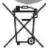
Overview
1 Spindle
2 Threaded flange
a Clamping flange
b Clamping nut
3 Guard hood
Can be adjusted without a tool through 360^ by means of 12 notches.
4 Spindle lock
Secures the spindle when the tool is changed.
5 Gear head
With air outlet and direction-of-rotation arrow.
6 Switch rocker
Switches the power tool on and off.
With notched position for continuous operation.
7 Rear handle
8 Rating plate *
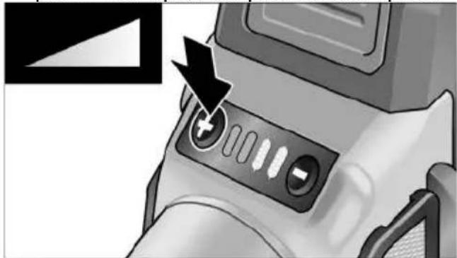
9 Speed control button
(for LBE 125 18.0-EC)
+/- function with 4 levels
10 Filter cover
11 Handle
Handle can be fitted to the left or right.
12 Li-ion battery (2.5 Ah/5.0 Ah/8.0 Ah)
13 Release button for battery
14 State of charge indicator
15 Pin wrench
Instructions for use

WARNING!
Remove the battery before carrying out any work on the power tool.
Before switching on the power tool
Unpack the angle grinder and check that there are no missing or damaged parts.
i NOTE
The batteries are not fully charged on delivery. Prior to initial operation, charge the batteries fully. Refer to the charger operating manual.
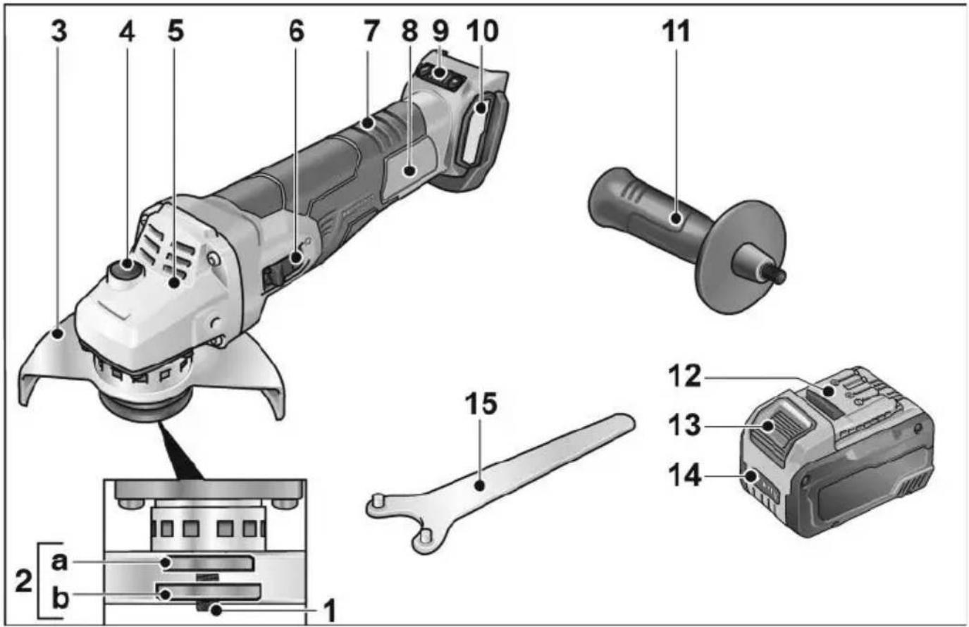
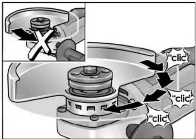
Inserting/replacing the battery
■ Press the charged battery into the power tool until it clicks into place.
■ To remove, press the release button (1.) and pull out the battery (2.).

CAUTION!
When the device is not in use, protect the battery contacts. Loose metal parts may short-circuit the contacts; explosion and fire hazard!
Battery state of charge
■ Press the button to check the state of charge at the state of charge indicator LEDs.
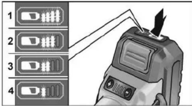
The indicator goes out after 5 seconds. If one of the LEDs flashes, the battery must be recharged. If none of the LEDs light up after the button is pressed, the battery is faulty and must be replaced.
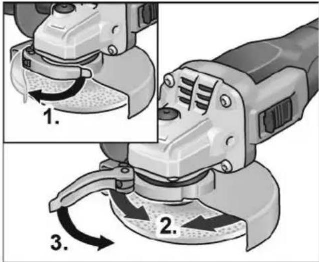
Attach the guard

WARNING!
When using the angle grinder for roughing or cutting, never work without the guard. A special cutting guard must be used for cutting.
■ Remove the battery.
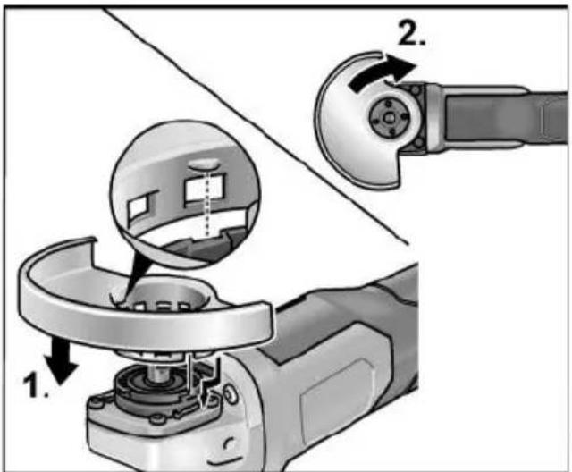
■ Attach the guard (1.). Lugs on the guard hood must be located in the flange recesses.
■ Turn guard hood clockwise (2). Rotation is possible in one direction only!
■ Remove in reverse order.
Mounting clamp-fit hood
■ Remove battery.
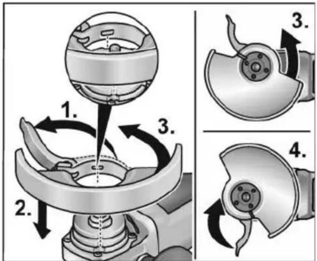
■ Open clamping lever (1.).
■ Attach clamp-fit hood with clamping ring to clamping flange, guiding cams on clamping ring into groove on flange when doing so (2.).
■ Turn clamp-fit hood in clockwise direction to the desired position (3.) and tighten the clamping lever (4.).
■ Remove in reverse order.
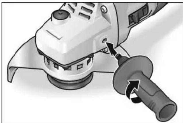
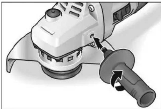
Attach the handle
natural_image
Close-up of a robotic grinding machine with a tool inserted, showing the blade being cut (no text or symbols visible)i NOTE
It is not permitted to operate the electric power tool without the handle.
Attaching/changing the tool
■ Remove the battery. Attach the grinding wheel
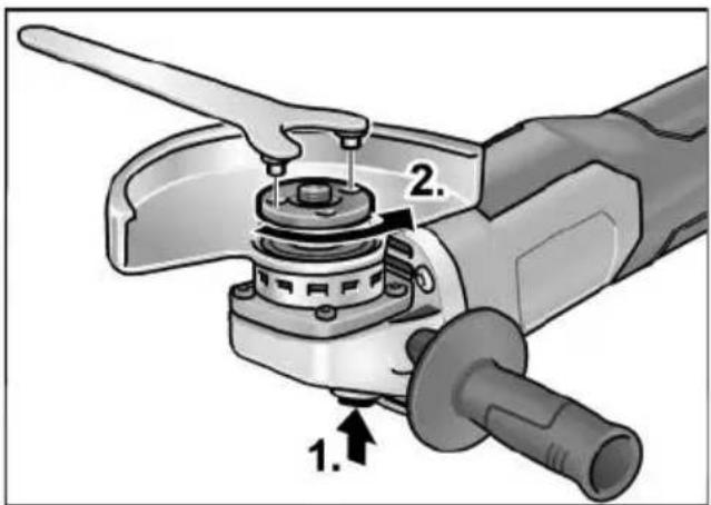
■ Press and hold down the spindle lock (1.).
■ Using the pin wrench, loosen the clamping nut on the spindle in an anticlockwise direction and remove (2.).
■ Insert the grinding wheel in the correct position.
■ Screw the clamping nut with flange face up, onto the spindle.
■ Press and hold down the spindle lock.
■ Tighten the clamping nut with the pin wrench.
- Carry out a test run to check that the tool is clamped in the centre.
Test run
■ Insert the battery.
■ Switch on the angle grinder with the switch (without engaging it) and run the angle grinder for approx. 30 seconds. Check for imbalances and vibrations.
■ Switch off the angle grinder.
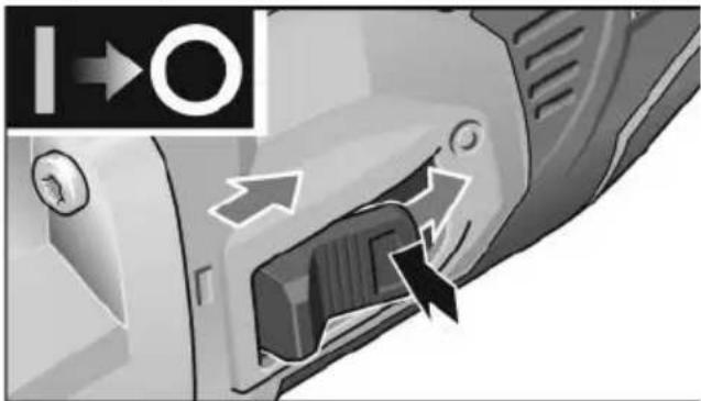
Switching on and off
Brief operation without engaged switch rocker
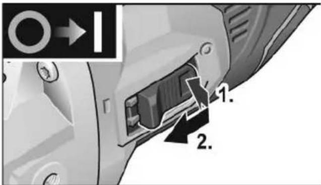
■ Press switch (1.), push towards front and hold (2.).
■ To switch off the power tool, release the switch rocker.
Continuous operation with engaged switch rocker
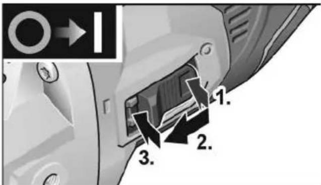
■ Press switch (1.), push towards front (2.) and engage at front end by applying pressure (3.).

natural_image
Close-up of a car's air vent with directional arrows indicating airflow or movement (no text or symbols)■ To switch off the power tool, release the switch rocker by pressing the rear end.
i NOTE
Following a power failure, the switched on power tool does not restart.
Preselecting the speed (for LBE 125 18.0-EC)
■ To set the operating speed, press the speed control button. Selected speed is maintained even when switching off.
■ Gently press the switch to accelerate the power tool up to the preselected speed.
natural_image
Close-up of a camera lens control panel with an arrow pointing to the button (no text or symbols visible)CAUTION!
Risk of injury due to destruction of the tool. Use the appropriate tool for the job.
i NOTE
- Overload protection: switches the machine off in the event of overload.
- Sensor-controlled temperature monitoring: If there is a risk of overheating the machine switches off.
Adjusting the guard
To adjust the tool to the task at hand, the guard hood can be adjusted by 12 notches on 360° without a tool.
CAUTION!
Risk of injury! Wear protective gloves.
■ Remove the battery.
■ Turn guard hood opposite to the direction-of-rotation arrow on the gear head to the required position.
Adjusting clamp-fit hood
■ Release clamping lever (1.).
■ Adjust clamp-fit hood (2.).
■ Tighten clamping lever again (3.).
i NOTE
The protective hood must be held firmly to prevent it from turning. If necessary, before operating the clamping lever, tighten the hexagon nut until the lever can just be actuated by hand.
Work instructions
i NOTE
When the power tool is switched off, the grinding tool continues running briefly.
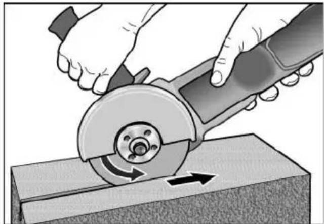
Rough-grinding
WARNING!
Never use cutting-off wheels for rough-grinding.
- Angle of wheel 20–40° for best cutting performance.
- Applying moderate pressure, move the angle grinder backwards and forwards. As a result, the workpiece will not become too hot and there will be no discoloration; nor will there be any grooves.
Cut-off grinding
WARNING!
A special cutting guard must be used for cutting.
See manufacturer's accessories catalogue.
- The angle grinder must always be operated backwards.
natural_image
Illustration of hands using a cutting tool to cut a metal block, showing angular motion (no text or symbols)Otherwise, there is a risk of the angle grinder jumping uncontrollably out of the groove.
- Do not press, tilt or oscillate the power tool.
- Adjust the feed to the material which is to be cut: the harder the material, the slower the feed.
For further information on the manufacturer's products go to www.flex-tools.com.
Maintenance and care
WARNING!
Remove the battery before carrying out any work on the power tool.
Cleaning
■ Regularly clean the power tool and ventilation slots. Frequency of cleaning is dependent on the material and duration of use.
■ Regularly blow out the housing interior and motor with dry compressed air.
■ Regularly clean the filter cover.

natural_image
Two-panel diagram showing mechanical component changes, with arrows indicating direction of movement (no text or symbols)■ Remove filter cover and blow it out with dry compressed air.
Gears

NOTE
Do not loosen the screws on the gear head during the warranty period. Non-compliance will deem the guarantee obligations of the manufacturer null and void.
Repairs
Repairs may be carried out by an authorised customer service centre only.
Spare parts and accessories
For other accessories, in particular grinding tools, see the manufacturer's catalogues. Exploded drawings and spare-part lists can be found on our homepage:
www.flex-tools.com
Disposal information

WARNING!
Render redundant power tools unusable:
- mains operated power tool by removing the power cord,
- battery operated power tool by removing the battery.

EU countries only
Do not throw electric power tools into the household waste!
In accordance with the European Directive 2012/19/EU on Waste Electrical and Electronic Equipment and transposition into national law used electric power tools must be collected separately and recycled in an environmentally friendly manner.

Raw material recovery instead of waste disposal.
Device, accessories and packaging should be recycled in an environmentally friendly manner. Plastic parts are identified for recycling according to material type.

WARNING!
Do not throw batteries into the household waste, fire or water. Do not open used batteries.
EU countries only:
In accordance with Directive 2006/66/EC defective or used batteries must be recycled.

NOTE
Please ask your dealer about disposal options!
C ∈ Declaration of Conformity
We declare under our sole responsibility that the product described under “Technical specifications” conforms to the following standards or normative documents: EN 60745 in accordance with the regulations of the directives 2014/30/EU, 2006/42/EC, 2011/65/EU.
Responsible for technical documents:
Peter Lameli Technical Head
Klaus Peter Weinper Head of Quality Department (QD)
15.12.2020
Declaration of Conformity
We as the manufacturer: FLEX
Business address: Bahnhofstr. 15,
71711 Steinheim, Germany
declare under our sole responsibility, that the product(s) described under „Technical specifications“ fulfills all the relevant provisions of The Supply of Machinery (Safety) Regulations S.I. 2008/1597 and also fulfills all the relevant provisions of the following UK Regulations:
Electromagnetic Compatibility Regulations S.I. 2016/1091, The Restriction of the Use of Certain Hazardous Substances in Electrical and Electronic Equipment Regulations S.I. 2012/3032 and are manufactured in accordance with the following designated Standards: BS EN 60745-1:2010, BS EN 60745-2-3:2011, BS EN 55014-1:2017, BS EN 55014-2:2015
Place of declaration: Steinheim, Germany.
Responsible person: Peter Lameli,
Contact details for Great Britain:
FLEX Power Tools Limited,
Unit 8 Anglo Office Park, Lincoln Road,
HP 12, 3RH Buckinghamshire,
United Kingdom

Peter Lameli
Technical Head

Klaus Peter Weinper
Head of Quality
Department (QD)
19.05.2021
Exemption from liability
The manufacturer and his representative are not liable for any damage and lost profit due to interruption in business caused by the product or by an unusable product.
The manufacturer and his representative are not liable for any damage which was caused by improper use of the product or by use of the product with products from other manufacturers.
Table des matières
natural_image
Close-up of a white electric grinder with a tool inserted, showing the blade being cut (no text or symbols visible)i REMARQUE
natural_image
Close-up of a car interior showing a door handle and internal air vent, with directional arrows indicating flow or movement (no text or symbols)natural_image
Close-up of a camera lens control panel with an arrow pointing to the button (no text or symbols visible)
PRUDENCE!
natural_image
Illustration of hands using a cutting tool to cut a metal sheet (no text or symbols visible)natural_image
Close-up of a car door panel with a black arrow pointing to the side panel (no text or symbols visible)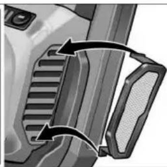
natural_image
Close-up of a mechanical component with two curved arrows indicating motion or assembly (no text or symbols visible)Peter Lameli Technical Head
Klaus Peter Weinper Head of Quality Department (QD)
natural_image
Close-up of a white electric grinder with a tool inserted, showing the blade being cut (no text or symbols visible)i AVVISO
natural_image
Close-up of a camera lens control panel with an arrow pointing to the button (no text or symbols visible)
PRUDENZA!
natural_image
Illustration of hands using a cutting tool to cut a metal sheet (no text or symbols visible)natural_image
Two-panel illustration showing a vehicle's side profile of the door and grille, with arrows indicating rotational movement (no text or symbols)natural_image
Close-up of a white electric grinder with a tool inserted, showing the blade and handle (no text or symbols visible)i NOTA
natural_image
Close-up of a car's side panel showing airflow direction arrows (no text or symbols)natural_image
Close-up of a camera lens control panel with an arrow pointing to the button (no text or symbols visible)¡PRECAUCIÓN!
natural_image
Illustration of hands using a cutting tool to cut a metal sheet (no text or symbols visible)natural_image
Close-up of a car door panel with a black arrow pointing to the side panel (no text or symbols visible)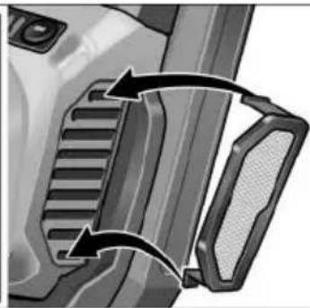
natural_image
Close-up of a mechanical component with two arrows indicating direction (no text or symbols visible)Peter Lameli Technical Head
Klaus Peter Weinper Head of Quality Department (QD)
(2,5 Ah/5,0 Ah/8,0 Ah)
natural_image
Close-up of a robotic grinding tool with a workpiece, showing a turning process (no text or symbols visible)INDICAÇÃO
natural_image
Close-up of a car's side panel showing a button and directional arrows (no text or symbols)natural_image
Close-up of a camera lens control panel with an arrow pointing to the button (no text or symbols visible)CAUTION!
natural_image
Illustration of hands using a cutting tool to cut a metal sheet (no text or symbols visible)natural_image
Close-up of a car door panel with a curved arrow indicating rotation or movement (no text or symbols visible)
natural_image
Close-up of a mechanical component with two curved arrows indicating motion or assembly (no text or symbols visible)EN 60745 de acordo com as determinações das directivas 2014/30/UE, 2006/42/CE, 2011/65/UE.
Peter Lameli Technical Head
Klaus Peter Weinper Head of Quality Department (QD)
12 Li-ion-accu (2,5 Ah/5,0 Ah/8,0 Ah)
natural_image
Close-up of a robotic grinding machine tool with a rotating knob (no text or symbols visible)i LET OP
natural_image
Close-up of a car's front panel showing directional arrows and a lock mechanism (no text or symbols)natural_image
Close-up of a camera lens control panel with buttons and a black arrow pointing to the button (no text or symbols visible)VOORZICHTIG!
■ De spanhendel openen (1.).
■ De spankap verstellen (2.).
■ De spanhendel weer vastdraaien (3.).
i LET OP
natural_image
Illustration of hands using a cutting tool to cut a metal block, showing rotational motion (no text or symbols)natural_image
Mechanical component diagrams showing two views of a gear or cam mechanism with arrows indicating motion (no text or symbols)Peter Lameli Technical Head

Klaus Peter Weinper Head of Quality Department (QD)
15-12-2020
natural_image
Close-up of a white electric grinder with a tool inserted, showing the blade being cut (no text or symbols visible)i BEMAERK
natural_image
Close-up of a mechanical component with directional arrows indicating movement or flow (no text or symbols)■ Frigør vippekontakten ved at trykke på bagerste ende for at slukke.
natural_image
Close-up of a camera lens control panel with an arrow pointing to the button (no text or symbols visible)! FORSIGTIG!
natural_image
Illustration of hands using a cutting tool to cut a metal sheet, showing motion direction (no text or symbols)natural_image
Two grayscale illustrations showing a vehicle's side profile changes in the front and rear views, with arrows indicating motion direction (no text or symbols present)
Peter Lameli
Technical Head

Klaus Peter Weinper Head of Quality Department (QD)
15.12.2020
12 Li-lon-batteri (2,5 Ah/5,0 Ah/8,0 Ah)
natural_image
Close-up of a robotic grinding machine with a tool, showing the angle and cutting edge (no text or symbols visible)i HENVISNING
natural_image
Close-up of a mechanical device's internal component with directional arrows indicating movement (no text or symbols)natural_image
Close-up of a camera lens control panel with buttons and an arrow pointing to the button (no text or symbols visible)FORSIKTIG!
■ Løsne spennarmen (1.).
■ Juster klemdekselet (2.).
■ Stram spennarmen igjen (3.).
i HENVISNING
natural_image
Illustration of hands using a cutting tool to cut a metal sheet, showing motion direction (no text or symbols)natural_image
Close-up of a car door handle with a black arrow pointing to the right side (no text or symbols visible)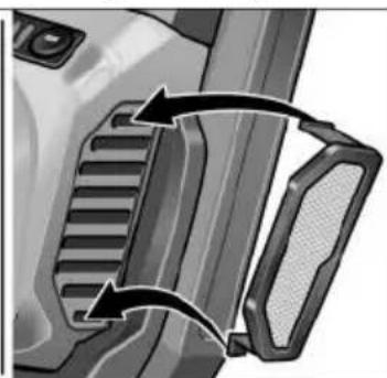
natural_image
Close-up of a mechanical component with two curved arrows indicating motion or force direction (no text or symbols)12 Litiumjonbatteri (2,5 Ah/5,0 Ah/8,0 Ah)
natural_image
Illustration of a device with a 'click' speech bubble (no text or symbols on the device itself)
natural_image
Close-up of a power tool with a knob and handle, showing mechanical components (no text or symbols visible)i OBS
natural_image
Close-up of a mechanical device's internal component with directional arrows indicating movement (no text or symbols)natural_image
Close-up of a camera lens control panel with an arrow pointing to the button (no text or symbols visible)VAR FÖRSIKTIG!
natural_image
Illustration of hands using a cutting tool to cut a metal sheet (no text or symbols visible)natural_image
Two-panel diagram showing mechanical component changes with arrows indicating motion (no text or symbols)Peter Lameli Technical Head

Klaus Peter Weinper Head of Quality Department (QD)
15.12.2020
natural_image
Close-up of a robotic grinding machine tool with a rotating knob (no text or symbols visible)i OHJE
natural_image
Close-up of a mechanical component with directional arrows indicating movement or flow (no text or symbols)natural_image
Close-up of a camera lens control panel with buttons and a black arrow pointing to the button (no text or symbols visible)HUOMIO!
natural_image
Illustration of hands using a cutting tool to cut a metal sheet, showing a rotating cutter and cutting edge (no text or symbols)natural_image
Two-panel diagram showing mechanical component changes, with arrows indicating motion direction (no text or symbols)Peter Lameli Technical Head
Klaus Peter Weinper Head of Quality Department (QD)
15.12.2020
(2,5 Ah/5,0 Ah/8,0 Ah)
natural_image
Close-up of a power tool with a knob and blade, showing mechanical components (no text or symbols visible)i YΠΟΔΕΙΞΗ
natural_image
Close-up of a camera lens control panel with buttons and a black arrow pointing to the button (no text or symbols visible)ΠΡΟΣΟΧΗ!
natural_image
Illustration of hands using a cutting tool to cut a metal sheet (no text or symbols visible)natural_image
Close-up of a car door handle with a black arrow pointing to the side panel (no text or symbols visible)
natural_image
Close-up of a mechanical component with two arrows indicating rotational movement (no text or symbols)Klaus Peter Weinper
Head of Quality
Department (QD)
15.12.2020
natural_image
Close-up of a robotic grinding machine with a tool, showing the angle and cutting edge (no text or symbols visible)i BÍLGÍ
natural_image
Close-up of a mechanical component with directional arrows indicating movement or flow (no text or symbols)natural_image
Close-up of a camera lens control panel with buttons and an arrow pointing to the button (no text or symbols visible)⚠️ DİKKAT!
natural_image
Illustration of hands using a cutting tool to cut a metal sheet, showing rotational motion (no text or symbols)natural_image
Close-up of a car door panel with a curved arrow indicating rotation (no text or symbols)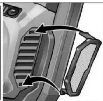
natural_image
Close-up of a vehicle's front bumper and side bumper with directional arrows indicating movement (no text or symbols)Peter Lameli Technical Head

Klaus Peter Weinper Head of Quality Department (QD)
15.12.2020
natural_image
Close-up of a power tool being cut with a wrench, showing the blade and angle (no text or symbols visible)WSKAZÓWKA
natural_image
Close-up of a car's front panel showing internal components and directional arrows (no text or symbols)natural_image
Close-up of a camera lens control panel with an arrow pointing to the button (no text or symbols visible)OSTROŻNIE!
natural_image
Illustration of hands using a cutting tool to cut a metal sheet, showing angular cutting (no text or symbols)natural_image
Close-up of a car door handle with a curved arrow indicating rotation (no text or symbols)
natural_image
Close-up of a vehicle's side profile showing grille and handle components (no text or symbols visible)Peter Lameli
Technical Head
Klaus Peter Weinper
Head of Quality
Department (QD)
15.12.2020
natural_image
Close-up of a robotic grinding machine tool with a rotating knob (no text or symbols visible)MEGJEGYZÉS
natural_image
Close-up of a mechanical device's internal component with directional arrows indicating flow or movement (no text or symbols)natural_image
Close-up of a camera lens control panel with buttons and a black arrow pointing to the button (no text or symbols visible)VIGYÁZAT!
natural_image
Illustration of hands using a cutting tool to cut a metal sheet (no text or symbols visible)natural_image
Close-up of a car door handle with a black arrow pointing to the side panel (no text or symbols visible)
natural_image
Close-up of a mechanical component with two curved arrows indicating rotational or directional movement (no text or symbols)Peter Lameli Technical Head
Klaus Peter Weinper Head of Quality Department (QD)
-
- 15
(2,5 Ah/5,0 Ah/8,0 Ah)
natural_image
Close-up of a robotic grinding machine tool with a rotating knob (no text or symbols visible)i UPOZORNĚNÍ
natural_image
Close-up of a car's door panel with directional arrows indicating movement or flow (no text or symbols)natural_image
Close-up of a camera lens control panel with an arrow pointing to the button (no text or symbols visible)POZOR!
natural_image
Illustration of hands using a cutting tool to cut a metal sheet (no text or symbols visible)natural_image
Close-up of a car door panel with a curved arrow indicating rotation or movement (no text or symbols visible)
natural_image
Close-up of a mechanical component with two arrows indicating direction (no text or symbols visible)Peter Lameli Technical Head
Klaus Peter Weinper
Head of Quality
Department (QD)
15.12.2020
■ Pri vyberaní stlačte zaist'ovacie tlačidlá (1.) a akumulátor vytiahnite (2.).

POZOR!
natural_image
Close-up of a power tool with a knob and blade, showing mechanical components (no text or symbols visible)i UPOZORNENIE
natural_image
Close-up of a car door handle with directional arrows indicating movement or flow (no text or symbols)natural_image
Close-up of a camera lens control panel with an arrow pointing to the button (no text or symbols visible)POZOR!
■ Uvoľnite upínaciu páčku (1.).
■ Upínací kryt prestavte (2.).
■ Upínaciu páčku znovu zatiahnite (3.).
i UPOZORNENIE
natural_image
Illustration of hands using a cutting tool to cut a metal sheet, showing the blade and cutting edge (no text or symbols)natural_image
Close-up of a car door panel with a black arrow pointing to the side panel (no text or symbols visible)
natural_image
Close-up of a mechanical component with two arrows indicating direction (no text or symbols visible)Peter Lameli Technical Head
Klaus Peter Weinper
Head of Quality
Department (QD)
15.12.2020
■ Stavite štitnik (1.). Izbočine na štitniku pritom moraju dosjesti u otvore prirubnica.
■ Štitnik zakrenite u smjeru kazaljke na satu (2.).
■ Otvorite steznu polugu (1.).
■ Stezni poklopac sa steznim prstenom stavite na steznu prirubnicu, pritom umetnite greben na steznom prstenu u utor na prirubnici (2.).
■ Okrenite stezni poklopac u smjeru kazaljke na satu u željeni položaj (3.) i pritegnite steznu polugu (4.).
■ Demontaža obrnutim redoslijedom.
Montaža ručke
natural_image
Close-up of a power tool with a knob and handle, showing mechanical components (no text or symbols visible)i NAPOMENA
natural_image
Close-up of a mechanical device's internal component with directional arrows indicating movement (no text or symbols)■ Za isključivanje deblokirajte klizač prekidača pritiskom na stražnji kraj.
natural_image
Close-up of a camera lens control panel with buttons and an arrow pointing to the button (no text or symbols visible)OPREZ!
natural_image
Illustration of hands using a cutting tool to cut a metal sheet (no text or symbols visible)U suprotnom postoji opasnost od nekontroliranog iskakanja iz utora.
natural_image
Two-panel diagram showing mechanical component changes, one with curved arrows indicating motion or assembly (no text or symbols)- Izvadite filtar za prašinu i ispušite suhim komprimiranim zrakom.
Prijenosnik
i NAPOMENA
Peter Lameli Technical Head
Klaus Peter Weinper Head of Quality Department (QD)
15.12.2020
Hrup in tresljaji 251
12 Litij-ionska akumulatorska baterija (2,5 Ah/5,0 Ah/8,0 Ah)
13 Gumb za deblokado akumulatorske baterije
14 Prikaz stanja napolnjenosti akumulatorske baterije
15 Ključ s kavljem
Navodila za uporabo

OPOZORILO!
natural_image
Close-up of a power tool with a knob and handle, showing mechanical components (no text or symbols visible)i NASVET
■ Prekucno stikalo pritisnite (1.), ga potisnite naprej (2.) in s pritiskom na sprednji del poskrbite, da se zaskoči (3.).
■ Za izklop pritisnite na zadnji del prekucnega stikala, da sprostite zaporo.
natural_image
Close-up of a camera lens control panel with an arrow pointing to the button (no text or symbols visible)PREVIDNO!
Nevarnost telesnih poškodb zaradi uničenja nastavka. Izberite primeren nastavek za delo, ki ga opravljate.
i NASVET
natural_image
Illustration of hands using a cutting tool to cut a metal block, showing motion direction (no text or symbols)natural_image
Close-up of a car door handle with a black arrow indicating rotation (no text or symbols)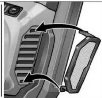
natural_image
Close-up of a mechanical component with two curved arrows indicating motion or force direction (no text or symbols)■ Snemite filter za prah in ga izpihajte s suhim stisnjenim zrakom.
Gonilo

NASVET
Med garancijsko dobo ne odstranjujte vijakov z glave gonila. V nasprotnem primeru prenehajo veljati garancijske obveznosti proizvajalca.
Popravila
Peter Lameli
Technical Head
Klaus Peter Weinper
Head of Quality
Department (QD)
15.12.2020
natural_image
Close-up of a power tool with a hammer and screwdriver, showing the process (no text or symbols visible)i OBSERVATIE
natural_image
Close-up of a car's side panel showing airflow direction arrows (no text or symbols)natural_image
Close-up of a camera lens control panel with buttons and a black arrow pointing to the button (no text or symbols visible)ATENTIE!
natural_image
Illustration of hands using a cutting tool to cut a metal sheet, showing the blade and cutting edge (no text or symbols)natural_image
Close-up of a car door handle with a curved arrow indicating rotation (no text or symbols)
natural_image
Close-up of a mechanical component with two arrows indicating direction (no text or symbols visible)EN 60745 conform prevederilor Directivelor 2014/30/UE, 2006/42/CE, 2011/65/UE.
Responsabili pentru documentația tehnica: FLEX-Elektrowerkzeuge GmbH, R & D Bahnhofstrasse 15, D-71711 Steinheim/Murr

Peter Lameli Technical Head
Klaus Peter Weinper Head of Quality Department (QD)
15.12.2020
natural_image
Close-up of a power tool with a hammer and screwdriver, showing the process of angleing operation (no text or symbols visible)i УКАЗАНИЕ
natural_image
Close-up of a mechanical device's internal component with directional arrows indicating movement (no text or symbols)natural_image
Close-up of a camera lens with adjustment knobs and a black arrow pointing to the button (no text or symbols visible)ВНИМАНИЕ!
natural_image
Illustration of hands using a cutting tool to cut a metal sheet (no text or symbols visible)natural_image
Close-up of a car door handle with a curved arrow indicating rotation (no text or symbols)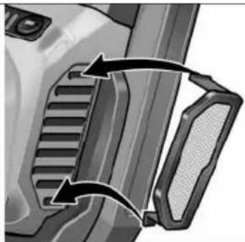
natural_image
Close-up of a mechanical component with two arrows indicating direction (no text or symbols visible)Peter Lameli Technical Head

Klaus Peter Weinper
Head of Quality
Department (QD)
15.12.2020
natural_image
Illustration of a device with a 'click' speech bubble (no text or symbols on the device itself)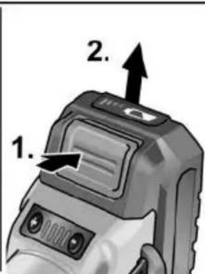
natural_image
Close-up of a power tool with a knob and handle, showing mechanical components (no text or symbols visible)i ПРИМЕЧАНИЕ
natural_image
Close-up of a camera lens control panel with buttons and a black arrow pointing to the button (no text or symbols visible)ВНИМАНИЕ!
natural_image
Illustration of hands using a cutting tool to cut a metal block, showing angular motion (no text or symbols)natural_image
Close-up of a car door handle with a black arrow pointing to the side panel (no text or symbols visible)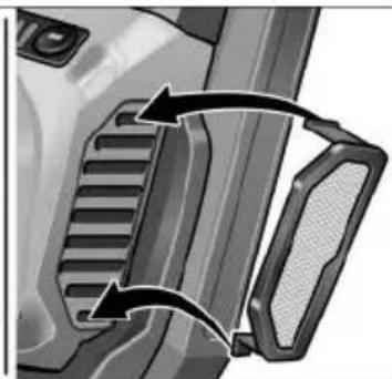
natural_image
Close-up of a mechanical component with two arrows indicating direction (no text or symbols visible)Peter Lameli Technical Head
Klaus Peter Weinper Head of Quality Department (QD)
natural_image
Close-up of a power tool with a hammer and screwdriver, showing the process (no text or symbols visible)i MÄRKUS
natural_image
Close-up of a car's front panel showing airflow direction and component placement (no text or symbols)natural_image
Close-up of a camera lens with adjustment knobs and a black arrow pointing to the button (no text or symbols visible)ETTEVAATUST!
■ Vabastage kinnitushoob (1.).
■ Reguleerige klemmkatet (2.).
■ Pingutage uuesti kinnitushoob (3.).
i MÄRKUS
natural_image
Illustration of hands using a cutting tool to cut a metal sheet (no text or symbols visible)natural_image
Close-up of a car door handle with a black arrow pointing to the side panel (no text or symbols visible)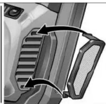
natural_image
Close-up of a mechanical component with two arrows indicating direction (no text or symbols visible)Peter Lameli Technical Head

Klaus Peter Weinper Head of Quality Department (QD)
15.12.2020
natural_image
Close-up of a power tool being cut with a wrench, showing the blade and angle (no text or symbols visible)NURODYMAS
natural_image
Close-up of a car's front panel showing the door handle and internal components, with directional arrows indicating movement (no text or symbols)natural_image
Close-up of a camera lens control panel with an arrow pointing to the button (no text or symbols visible)ATSARGIA!!
natural_image
Illustration of hands using a cutting tool to cut a metal block, showing angular motion (no text or symbols)natural_image
Close-up of a car door panel with a black arrow pointing to the side panel (no text or symbols visible)
natural_image
Close-up of a mechanical component with two curved arrows indicating motion or force direction (no text or symbols visible)Peter Lameli Technical Head
Klaus Peter Weinper
Head of Quality
Department (QD)
15.12.2020
■ Lai akumulatoru iznemtu, nospiediet atblokēšanas taustinu (1.) un iznemiet akumulatoru (2.).
UZMANĪBU!
natural_image
Close-up of a robotic grinding machine tool with a rotating knob (no text or symbols visible)i NORĀDĪJUMS
Lietot elektroinstrumentu bez roktura nav atļauts.
natural_image
Close-up of a mechanical component with directional arrows indicating movement or flow (no text or symbols)natural_image
Close-up of a camera lens with adjustment knob and control buttons (no text or symbols visible)UZMANĪBU!
■ Atlaidiet spīlsviru (1.).
natural_image
Illustration of hands using a cutting tool to cut a metal sheet (no text or symbols visible)natural_image
Mechanical component diagrams showing two views of a bracket with internal channels and arrows indicating motion (no text or symbols)■ Nonemiet puteklu filtru un izpūtiet to ar sausu saspiesto gaisu.
Pārvads

NORĀDĪJUMS
natural_image
Illustration of hands using a cutting tool to cut a metal sheet (no text or symbols visible)natural_image
Close-up of a car door panel with a mesh grille and an arrow indicating clockwise motion (no text or symbols)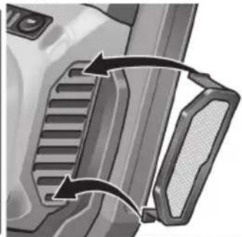
natural_image
Close-up of a mechanical component with two curved arrows indicating motion or force direction (no text or symbols visible)(1.) قم بфик ذراع الشد
natural_image
Close-up of a camera lens with adjustment knobs and a black arrow pointing to the button (no text or symbols visible)احترس!

natural_image
Close-up of a car's front panel showing airflow direction and component placement (no text or symbols)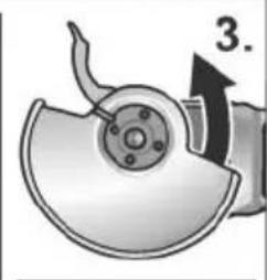
natural_image
Mechanical component diagram showing a disassembled fan or dial assembly with a numbered arrow (no text or symbols present)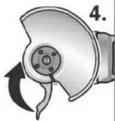
natural_image
Mechanical component diagram showing a rotating arm and housing (no text or symbols)natural_image
Illustration of a grinding machine tool with a rotating knob and handle (no text or symbols)تنييه!

natural_image
Illustration of a device with a 'click' speech bubble, no readable text or symbols present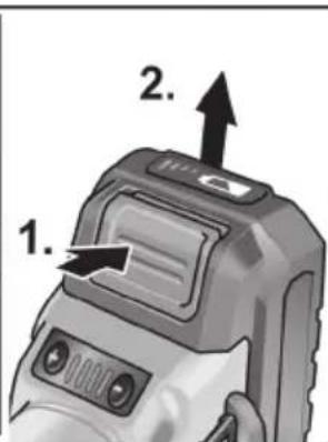


- i HINWEIS
- VORSICHT!
- Symbols used in this manual
- WARNING!
- CAUTION!
- NOTE
- Symbols on the power tool
- For your safety
- Intended use
- Safety Warnings for Angle Grinder
- Safety Warnings Common for Grinding, Sanding, Wire Brushing or Abrasive Cutting-Off Operations
- Kickback and Related Warnings
- Safety Warnings Specific for Grinding and Abrasive Cutting-Off Operations
- Additional Safety Warnings specific for Abrasive Cutting-Off Operations
- Safety Warnings Specific for Sanding Operations
- Safety Warnings Specific for Wire Brushing Operations
- Additional safety instructions
- Safety instructions for handling batteries
- Special safety instructions
- Noise and vibration
- Overview
- Instructions for use
- Before switching on the power tool
- i NOTE
- Inserting/replacing the battery
- Battery state of charge
- Attach the guard
- Mounting clamp-fit hood
- Attach the handle
- Attaching/changing the tool
- Test run
- Switching on and off
- Brief operation without engaged switch rocker
- Continuous operation with engaged switch rocker
- Preselecting the speed (for LBE 125 18.0-EC)
- Adjusting the guard
- Adjusting clamp-fit hood
- Work instructions
- Cut-off grinding
- Maintenance and care
- Cleaning
- Gears
- Repairs
- Spare parts and accessories
- Disposal information
- C ∈ Declaration of Conformity
- Declaration of Conformity
- Exemption from liability
- Table des matières
- i REMARQUE
- PRUDENCE!
- i AVVISO
- PRUDENZA!
- i NOTA
- ¡PRECAUCIÓN!
- INDICAÇÃO
- i LET OP
- VOORZICHTIG!
- i BEMAERK
- ! FORSIGTIG!
- i HENVISNING
- FORSIKTIG!
- VAR FÖRSIKTIG!
- i OHJE
- HUOMIO!
- i YΠΟΔΕΙΞΗ
- ΠΡΟΣΟΧΗ!
- i BÍLGÍ
- ⚠️ DİKKAT!
- WSKAZÓWKA
- OSTROŻNIE!
- MEGJEGYZÉS
- VIGYÁZAT!
- i UPOZORNĚNÍ
- POZOR!
- i UPOZORNENIE
- Montaža ručke
- i NAPOMENA
- OPREZ!
- Prijenosnik
- Navodila za uporabo
- OPOZORILO!
- i NASVET
- PREVIDNO!
- Gonilo
- NASVET
- Popravila
- i OBSERVATIE
- ATENTIE!
- i УКАЗАНИЕ
- ВНИМАНИЕ!
- i ПРИМЕЧАНИЕ
- i MÄRKUS
- ETTEVAATUST!
- NURODYMAS
- ATSARGIA!!
- UZMANĪBU!
- i NORĀDĪJUMS
- Pārvads
- NORĀDĪJUMS
Brand : Flex
Model : LBE 125 18.0-EC
Category : Grinder