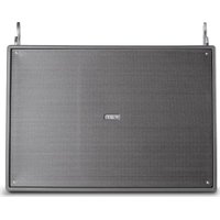
MITUS 210MA - Speaker FBT - Free user manual and instructions
Find the device manual for free MITUS 210MA FBT in PDF.


User questions about MITUS 210MA FBT
0 question about this device. Answer the ones you know or ask your own.
Ask a new question about this device
Download the instructions for your Speaker in PDF format for free! Find your manual MITUS 210MA - FBT and take your electronic device back in hand. On this page are published all the documents necessary for the use of your device. MITUS 210MA by FBT.
USER MANUAL MITUS 210MA FBT
CONTROLS AND FUNCTIONS
206LA / 206L
212FSA/212FS
210MA/210M
112A/115A-112A/115
TROMBA RUOTABILE/ROTATABLE HORN (112/112A - 115/115A) 10
121SA/118SA-121S/118S
PRESET 12-13-14-15
TO REDUCE THE RISK OF FIRE OR ELECTRIC SHOCK DO NOT EXPOSE THIS EQUIPMENT TO RAIN OR MOISTURE

WHERE MARKED, THIS SYMBOL INDICATES A DANGEROUS NONISOLATED VOLTAGE INSIDE THE LOUDSPEAKER: SUCHVOLTAGE COULD BE SUFFICIENT TO RESULT IN THE RISK OF ELECTRIC SHOCK.

WHERE MARKED, THIS SYMBOL INDICATES IMPORTANT USAGE AND MAINTENANCE INSTRUCTIONS IN THE ENCLOSED DOCUMENTS. PLEASE REFER TO THE MANUAL.
IMPORTANT SAFETY INSTRUCTIONS
1) Read these instructions
2) Keep these instructions
3) Heed all warnings
4) Follow all instructions
5) Do not use this apparatus near water
6) Clean only with dry cloth
7) Do not block any ventilation openings. Install in accordance with the manufacturer's instructions.
8) Do not install near any heat sources, such as radiators, heat registers, stoves or other apparatus (including amplifiers) that produce heat
9) Do not defeat the safety purpose of the polarized or grounding-type plug. A polarized plug has two blades with one wider than the other. A grounding type plug has two blades and a third grounding prong. The wide blade or the third prong are provided for your safety. If the provided plug does not fit into your outlet, consult an electrician for replacement of the obsolete outlet.
10) Protect the power cord from being walked on or pinched particularly at plugs, convenience receptacles, and the point where they exit from the apparatus.
11) Only use attachments/accessories specified by the manufacturer.
12) Use only with the cart, stand, tripod, bracket, or table specified by the manufacturer or sold with the apparatus. When a cart is used, use caution when moving the cart/apparatus combination to avoid injury from tip-over.

13)Unplug this apparatus during lightning storms or when unused for long periods of time.
14) Refer all servicing to qualified service personnel. Servicing is required when the apparatus has been damaged in any way, such as power-supply cord or plug is damaged, liquid has been spilled or objects have fallen into the apparatus, the apparatus has been exposed to rain or moisture, does not operate normally, or has been dropped.
THE DEVICE MUST BE CONNECTED TO THE MAINS THROUGH A POWER OUTLET WITH A PROTECTIVE EARTH CONNECTION.
This device features a power outlet; install the device so that the outlet for the power cord is easily accessible.
PRECAUTIONS
° For proper air ventilation please make sure to leave sufficient clearance (min 11 inc.) on all sides of the device.
^ Please do not cover the ventilation slots with papers, table cloths, curtains, etc. in order not to prevent ventilation of the device.
^ Please do not place any naked flame source, such as lighted candles, on the device.
^ Please keep the device away from water springs and splashes and please do not place any objects containing liquids, such as vases, on the device.
The MITUS sound reinforcement series is the result of FBT's experience and passion for excellence. A comprehensive range of 2-way speakers for FOH applications, subwoofoers, stage monitor and line arrays in passive and bi-amplified designs. Whether in live or touring applications or in permanent installations, they will be appreciated by any musicians and professionals looking for the finest sound quality.
The MITUS 206LA is the flagship model of the range: a line array with 2 × 165mm woofers and a driver with 36mm exit throat coupled to a waveguide, engineered to meet the physical criteria of the ideal cylindrical wave source for the whole audio range. With a gas injection moulded polypropylene cabinet and built-in suspension system, MITUS 206LA is a great result of the mechanical and electronic engineering of FBT. Through use of the FBT aiming software program for PCs it is possible to simulate the SPL distribution and frequency response of the listening.
MITUS 212FSA is a 2 × 320 ~mm compact subwoofer with built-in suspension system, ideal to extend the low frequencies of MITUS 206LA in flying or ground-stacked line arrays.
MITUS 118SA and MUITUS121SA complete the subwoofer range with respectively 460mm and 530mm woofer. They are a perfect complement for MITUS satellites in live or permanent applications where they reinforce and extend the low frequency range with the high SPL they can offer. They are all made of birch plywood with black scratch resistant paint finish.
MITUS 115A and MITUS 112A are 2-way bi-amplified FOH speakers suitable for a wide range of applications, especially when matched along with the MITUS subs. They guarantee stunning sound quality in live events or permanent installations.
With a low and elegant profile enclosure design, the MITUS 210MA undoubtedly the most technologically advanced stage monitor of its own category. Two 250mm woofers - one of whom is coaxial - with 36mm drivers guarantee the highest fidelity and headroom for any live performances of TV broadcasts.
The whole MITUS series is equipped with:
-High quality B&C neodymium magnet woofers custom manufactured for FBT
- The latest generation of B&C compression drivers
-High efficiency class D power amp modules with switch mode power supplies fixed to a die-cast aluminum chassis
- DSP with A/D - D/Alow noise converters
-Neutrik Powercon IN & LINK out power receptacles
-A wide range of accessories makes the MITUS range extremely flexible for live or permanent installations
-New aluminum die-cast carrying handles
-Heavy duty metal grille with anti-resonance spacers and exclusive synthetic cloth
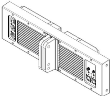
MITUS active systems display a high-efficiency Class D power amplifier module with switching power supply enclosed in a die-cast aluminium chassis.
This permits to protect the electronics against dust, avoid any air loss through the controls - which would cause annoying noises- and maximize heath loss by using the woofer ventilation instead of a cooling fan.
This allowed the development of a lightweight 1200W amplifier.
In the 206LA/206L models, the module works also as a bearing structure for flying the units and permits adjusting the inclination angle.
206LA 206L
Sistema line array a 2 vie compatto:
2 way compact line array system:
>2× 6.5'' B&C neodymium woofers with 1.7'' coil
>1.4'' exit B&C neodymium driver with 2.5" coil
Frequency response from 68Hz to 20kHz
Latest class D built in amplifiers, 600W RMS to the LF and 300W RMS to the HF with switch mode power supply
> DSP on board with 8 presets, + / - 5dB HF level control for accurate "amplitude shading".
Control panel with XLR input e link, volume, presets, HF level, HP filter, ground lift.
100^ horizontal waveguide with very low distortion and near flat wavefront up to 18kHz
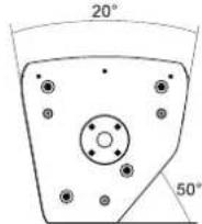
High impact polypropylene gas-injected enclosure with integrated rigging hardware adjustable with 0^ to 10^ angle between cabinets at 2^ step
Wide range of hardware accessories for flying and ground stacked configurationsVery lightweight, only 14kg
Passive version:
Recommended amplifier of 500W RMS / 16 Ohm LF and 150W RMS/ 16Ohm HF
Internal HF protection
Neutrik Speakon NL-4 connectors IN & LINK out
External digital processor required
THE MITUS 206L IS NOT EQUIPPED WITH INTERNAL PASSIVE
CROSSOVER; A CONNECTION TO THE POWER UNIT WITHOUT PROCESSOR WILL DAMAGE THE SPEAKERS

212FSA 212FS
Compact vented band pass subwoofer:
Same width and hardware suspension of the MITUS 206LA
2 x 12" B&C custom neodymium magnet high excursion woofers with 3" voice coil
Frequency response from 45Hz to 120Hz
Class D amplifier delivering 1200W RMS
DSP with 8 presets, cardioid and infra configurations, delay
Control panel with XLR input e link, volume, preset, delay, phase 0^ - 180^ , ground lift.
> 5/8" birch plywood enclosure, scratch resistant black paint
Low frequency extension cabinet for the MITUS 206LA line array for flying or ground stacked configurations
M20 top mount stand socket
Passive version:
Recommended amplifier 1000W RMS/8 Ohm.
Neutrik Speakon NL4 IN & LINK connectors.
External digital processor required
THE MITUS 212FS IS NOT EQUIPPED WITH INTERNAL PASSIVE CROSSOVER; A CONNECTION TO THE POWER UNIT WITHOUT PROCESSOR WILL DAMAGE THE SPEAKERS

210 MA 210 M
2 way bi-amplified, bass reflex design with coaxial driver:
1 x 10" B&C custom neodymium magnet coaxial speaker with 2.5" voice coiland1.4"exititaniumcompressiondriverwith2.5"voicecoil
B&Ccustom10"neodymiummagnetwooferwith2.5"voicecoil
Frequencyresponsefrom60Hzto20kHz
Class D built-in amplifiers, 600W RMS to the LF and 300W RMS to the HF withswitchmodepowersupply
DSPwith8eq.presents
ControlpanelwithXLRinputelink, volume, preset, HP filter, ground lift.
70°conicaldispersion
5/8"birchplywoodenclosure,scratchresistantblackpaintfinish
1.38"standssocketandbacksidecarryinghandle
Verylightweight,only19kg
Passive version:
Recommendedamplifier 800WRMS/4Ohm.
Hi-grade passive internal crossover featuring "soft trip" circuitry protectionofWFandTW
NeutrikSpeakonNL4IN&LINKoutconnectors.
112A 112
2 way bi-amplified bass reflex design:
>12^ \& C neodymium magnet woofer with 3^ voice coil
>1 exit B&C neodymium magnet HF driver with 1.7" voice coil
Frequency response from 50Hz to 20kHz
Class D amplifiers, 600W RMS to the LF and 300W RMS to the HF, switch mode power supply
DSPwith8eq.presents
Control panel with XLR input e link, volume, presets, HP filter, ground lift.
80°H x 50°V rotatable horn
> 5/8 birch plywood enclosure, scratch resistant black paint finish
12 x M10 fly points, 1.38" speaker stand socket and two FBT design aluminum handles
Ideal for live sound reinforcement applications as both front of house main PA and as a stage monitor
Weight 20kg
Passive version:
Recommended amplifier 700W RMS/4 Ohm.
Hi-grade passive internal crossover featuring "soft trip" circuitry protection of WF and TW transducers
Neutrik Speakon NL4 IN & LINK out connectors.
115A 115
2 way bi-amplified bass reflex design:
15" B&C neodymium magnet woofer with 3" voice coil
>1 exit B&C neodymium magnet HF driver with 1.7" voice coil
Frequency response from 46Hz to 20kHz
Class D amplifiers, 600W RMS to the LF and 300W RMS to the HF, switch mode power supply
DSP with 8 eq. presets
Control panel with XLR input e link, volume, presets, HP filter, ground lift.
> 80^ H × 50^ V rotatable horn
> 5/8 birch plywood enclosure, scratch resistant black paint finish
12 x M10 fly points, 1.38" speaker stand socket and two FBT design aluminum handles
Ideal for live sound reinforcement applications as both front of house main PA and as a stage monitor
Weight 20kg
Passive version:
Recommended amplifier 800W RMS/4 Ohm.
Hi-grade passive internal crossover featuring protection of WF and TW transducers
Neutrik Speakon NL4 IN & LINK out connectors.
121SA 121S
Large vented bass reflex subwoofer:
21" custom B&C neodymium high excursion woofer with 4.5" coil
Frequency response from 29Hz to 100Hz.
Class D amplifiers delivering 1200W RMS
> DSP with 8 presets,cardioid and infra configurations,delay.
Control panel with XLR input e link, volume preset, delay, phase 0^ - 180^ , ground lift.
>3/4 birch plywood enclosure with large reflex vent free from turbulence, scratch resistant black paint
M20 stand socket and six FBT design aluminum handles
4 swivel-mount casters 3.15" (optional)
Perfect low-frequency extension for the MITUS range
Passive version:
Recommended amplifier 2000W RMS / 4 Ohm.
Speakon NL4 IN & LINK connectors.
External digital processor required
THE MITUS 121S IS NOT EQUIPPED WITH INTERNAL PASSIVE CROSSOVER; A CONNECTION TO THE POWER UNIT WITHOUT PROCESSOR WILL DAMAGE THE SPEAKER.

118SA 118S
Subwoofer passa-banda compatto:
18" custom B&C neodymium high excursion woofer with 3" coil
Frequency response from 36Hz to 100Hz.
Class D amplifiers delivering 1200W RMS
DSP with 8 presets, cardioid and infra configurations, delay.
Control panel with XLR input e link, volume preset, delay, phase 0^ - 180^ , ground lift.
3/4" birch plywood enclosure , scratch resistant black paint
M20 stand socket and 2 FBT design aluminum handles
4 swivel-mount casters 3.15" (optional)
Perfect low-frequency extension for the MITUS range
Passive version:
Recommended amplifier 1000W RMS / 4 Ohm.
Speakon NL4 IN & LINK connectors.
External digital processor required
THE MITUS 118S IS NOT EQUIPPED WITH INTERNAL PASSIVE CROSSOVER; A CONNECTION TO THE POWER UNIT WITHOUT PROCESSOR WILL DAMAGE THE SPEAKER.

206LA
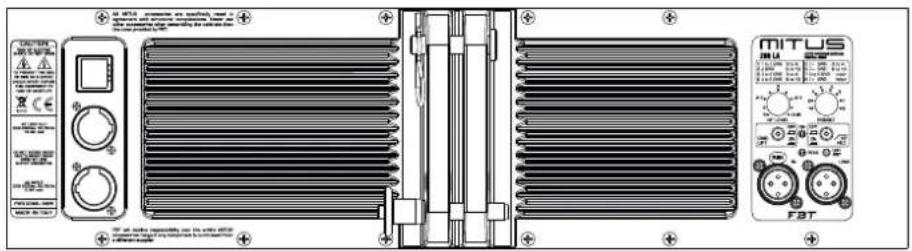
PRESET: Selects 8 presets, each of whom corresponds to a specific speaker configuration according to users' personal preferences and to the acoustics of the listening area (see PRESET section.)
HF LEVEL: Adjusts the volume of the driver and of one waveguide to be used in a range between -5dB and +5dB. With this level, the upper array modules can be set to obtain greater HF output power, thus reaching distant areas, and to attenuate the lower modules for a lower SPL towards the first rows of the venue; in this way all the listening area is handled gradually and optimally.
GND LIFT:A switch for the electric separation between the ground and earth circuits; this can be useful in order to remove the irritating noises caused by ground loops.
ON:Indicates that the system is on.
HP FILTER: This switch activates the low-cut filter which lets only the frequencies above the cut-off frequency pass at the output.
PEAK: When this LED lights up, it indicates that the signal is reaching saturation.
LMT/PRT: If this LED lights up, there is a system malfunction due to an internal amplifier failure or to the intervention of current limiting circuits against thermal overload.
IN-LINK: Balanced input/output sockets; "IN" allows to connect a pre-amplified signal such as that coming, for instance, from mixer output. "LINK" allows to connect multiple speakers to the same signal.
206L
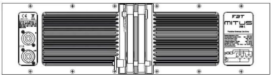
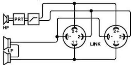
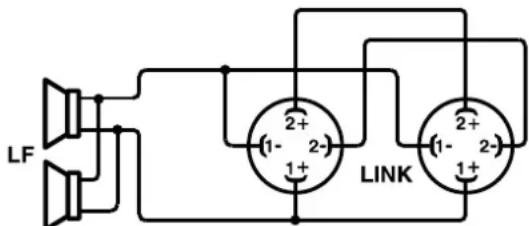
Speakon connectors are connected in parallel mode. One connector can be used to connect the box to the output of a power amplifier, the other to connect to a second box.
Loudspeaker cables shall have the adequate diameter, depending on the overall length of the connection. The resistance introduced by an inadequate wiring towards the loudspeakers would reduce both the power output and the damping factor of the loudspeaker.
*SPEAKON é un marchio registrato NEUTRIK
*SPEAKON is a registered trademark of NEUTRIK

212FSA
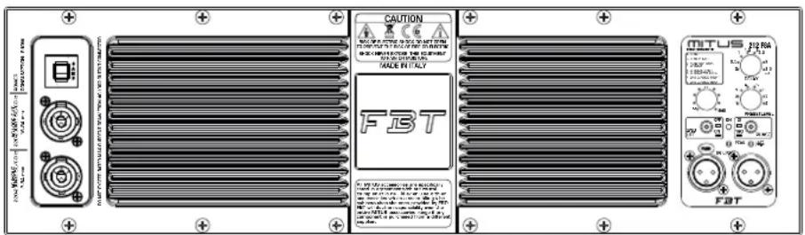
DELAY: Control of a digital delay line acting on the input signal; in this way it is possible to make up for the vertical misalignment of sub and satellite. The Delay is expressed in metres and goes from 0.5 to 3.5m with 50cm steps.
LEVEL: It adjusts the signal general level.
PRESET: Selects 8 presets, each of whom corresponds to a specific speaker configuration according to users' personal preferences and to the acoustics of the listening area (see PRESET section.)
GND LIFT:A switch for the electric separation between the ground and earth circuits; this can be useful in order to remove the irritating noises caused by ground loops.
ON: Indicates that the system is on.
PHASE: The Phase control allows to optimize phase alignment, i.e. to obtain a uniform frequency response in the crossover area between the sub and the satellite. When it is set at 0^ , the sound emission is in phase with the input signal; when it is set at 180^ the sound emission is in counterphase with the input signal; thanks to this control, subwoofer adjustment will be even more flexible with a consequent performance optimization.
PEAK: When this LED lights up, it indicates that the signal is reaching saturation.
LMT/PRT: If this LED lights up, there is a system malfunction due to an internal amplifier failure or to the intervention of current limiting circuits against thermal overload.
IN-LINK: Balanced input/output sockets; "IN" allows to connect a pre-amplified signal such as that coming, for instance, from mixer output. "LINK" allows to connect multiple speakers to the same signal.
212FS
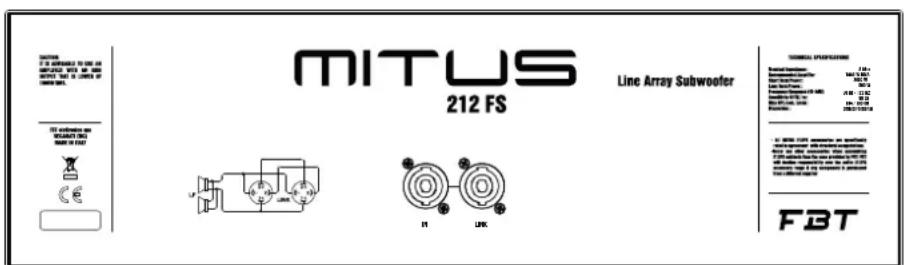
Speakon connectors are connected in parallel mode. One connector can be used to connect the box to the output of a power amplifier, the other to connect to a second box.
Loudspeaker cables shall have the adequate diameter, depending on the overall length of the connection. The resistance introduced by an inadequate wiring towards the loudspeakers would reduce both the power output and the damping factor of the loudspeaker.
*SPEAKON é un marchio registrato NEUTRIK
*SPEAKON is a registered trademark of NEUTRIK

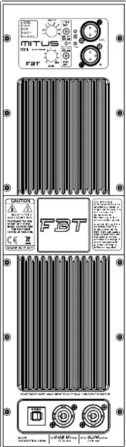
210MA
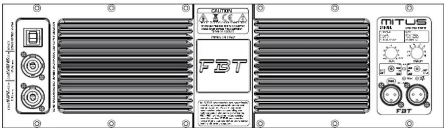
PRESET: Selects 8 presets, each of whom corresponds to a different equalization according to users' personal preferences and to the acoustics of the listening area (see PRESET section.)
LEVEL: Adjusts the signal general level.
GND LIFT:A switch for the electric separation between the ground and earth circuits; this can be useful in order to remove the irritating noises caused by ground loops.
ON: Indicates that the system is on.
HP FILTER: This switch activates the low-cut filter which lets only the frequencies above the cut-off frequency pass at the output.
PEAK: When this LED lights up, it indicates that the signal is reaching saturation.
LMT/PRT: If this LED lights up, there is a system malfunction due to an internal amplifier failure or to the intervention of current limiting circuits against thermal overload.
IN-LINK: Balanced input/output sockets; "IN" allows to connect a pre-amplified signal such as that coming, for instance, from mixer output. "LINK" allows to connect multiple speakers to the same signal.
210M
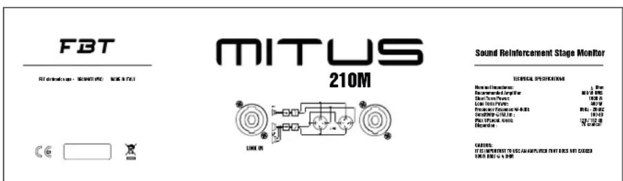
Speakon connectors are connected in parallel mode. One connector can be used to connect the box to the output of a power amplifier, the other to connect to a second box.
Loudspeaker cables shall have the adequate diameter, depending on the overall length of the connection. The resistance introduced by an inadequate wiring towards the loudspeakers would reduce both the power output and the damping factor of the loudspeaker.
*SPEAKON é un marchio registrato NEUTRIK
*SPEAKON is a registered trademark of NEUTRIK

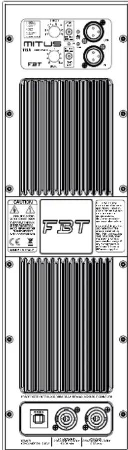
112A/115A
PRESET: Selects 8 presets, each of whom corresponds to a different equalization according to users' personal preferences and to the acoustics of the listening area (see PRESET section.)
LEVEL: Adjusts the signal general level.
GND LIFT: A switch for the electric separation between the ground and earth circuits; this can be useful in order to remove the irritating noises caused by ground loops.
ON: Indicates that the system is on.
HP FILTER: This switch activates the low-cut filter which lets only the frequencies above the cut-off frequency pass at the output.
PEAK: When this LED lights up, it indicates that the signal is reaching saturation.
LMT/PRT: If this LED lights up, there is a system malfunction due to an internal amplifier failure or to the intervention of current limiting circuits against thermal overload.
IN-LINK: Balanced input/output sockets; "IN" allows to connect a pre-amplified signal such as that coming, for instance, from mixer output. "LINK" allows to connect multiple speakers to the same signal.

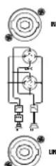
112/115

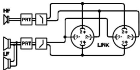
Speakon connectors are connected in parallel mode. One connector can be used to connect the box to the output of a power amplifier, the other to connect to a second box.
Loudspeaker cables shall have the adequate diameter, depending on the overall lenght of the connection. The resistance introduced by an inadequate wiring towards the loudspeakers would reduce both the power output and the damping factor of the loudspeaker.

*SPEAKON e un marchio registrato NEUTRIK *SPEAKON is a registered trademark of NEUTRIK
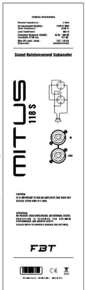
TECHNICAL SPECIFICATIONS
Research Interests
Department of Electrical Engineering
University of Toronto
Toronto, ON H3N2-1A5X
Researcher Abstracts 2010
Seminars: 2010/11/01
8.0mm 144W
156W
120W 30Hz 18MHz 170/120W
Sound Reinforcement Speaker

15
CAPITALS CAPITALS OF THE ASSETS AND LIABILITIES WITH AN OTHER OPERATING STATEMENT OF FINANCIAL POSITION

FET deTncaa aee - RECAUAT (N) NNE INIIT
112/112A
115/115A
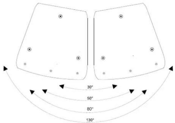
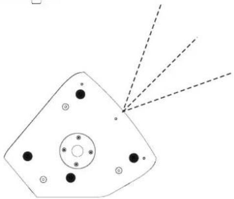
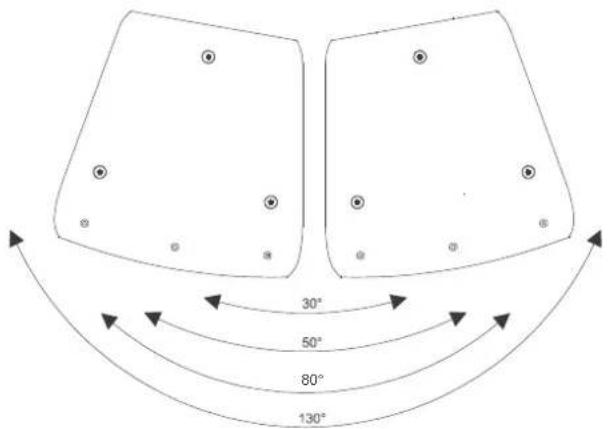
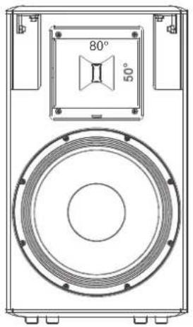
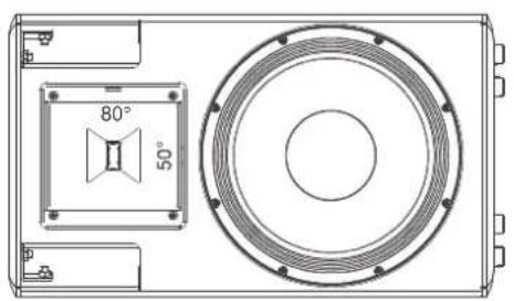
MITUS 112 and MITUS 115 models have an asymmetrical dispersion rotatable horn.
By removing the fixing screws of the horn it is possible to rotate it so as to change the dispersion angle when the speakers are used in horizontal position or when they are aligned in an array.
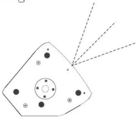
30^ ---- with 50^ horn position
50^ ---- with 80^ horn position
80^ ---- total coverage with 50^ horn position
130°----total coverage with 80^ horn position
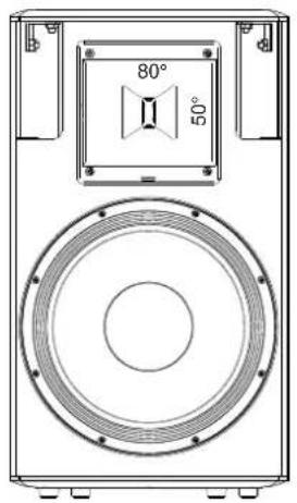
FRONT OF HOUSE
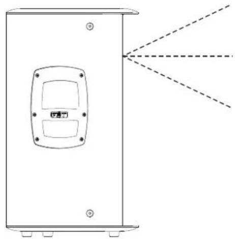
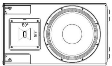
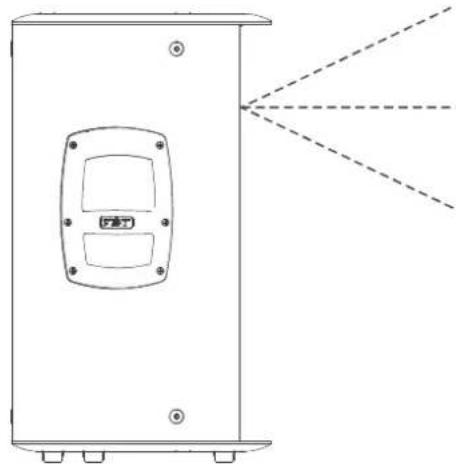
STAGE MONITOR
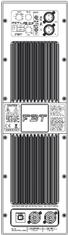
121SA/118SA
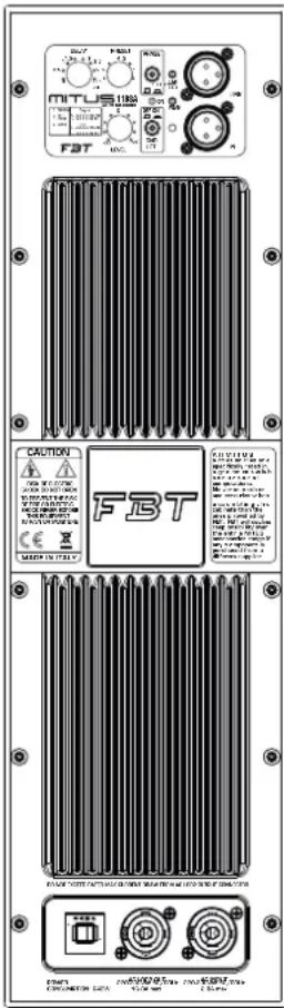
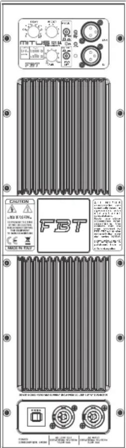
DELAY: Control of a digital delay line acting on the input signal; in this way it is possible to make up for the vertical misalignment of sub and satellite. The Delay is expressed in metres and goes from 0.5 to 3.5m with 50cm steps.
LEVEL: It adjusts the signal general level. PRESET: Selects 8 presets, each of whom corresponds to a specific speaker configuration according to users' personal preferences and to the acoustics of the listening area (see PRESET section.)
GND LIFT: A switch for the electric separation between the ground and earth circuits; this can be useful in order to remove the irritating noises caused by ground loops.
ON: Indicates that the system is on.
PHASE: The Phase control allows to optimize phase alignment, i.e. to obtain a uniform frequency response in the crossover area between the sub and the satellite. When it is set at 0^ , the sound emission is in phase with the input signal; when it is set at 180^ the sound emission is in counterphase with the input signal; thanks to this control, subwoofer adjustment will be even more flexible with a consequent performance optimization.
PEAK: When this LED lights up, it indicates that the signal is reaching saturation.
LMT/PRT: If this LED lights up, there is a system malfunction due to an internal amplifier failure or to the intervention of current limiting circuits against thermal overload.
IN-LINK: Balanced input/output sockets; "IN" allows to connect a pre-amplified signal such as that coming, for instance, from mixer output. "LINK" allows to connect multiple speakers to the same signal.
121S/118S
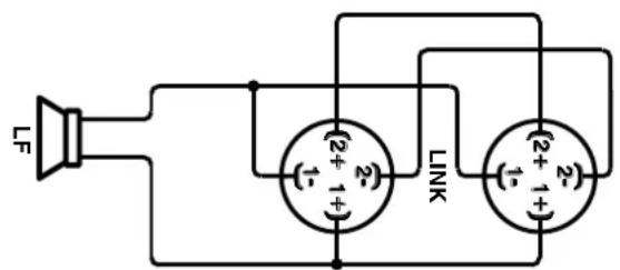
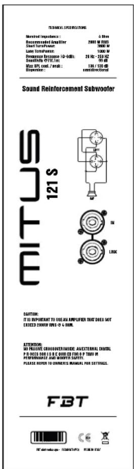
Speakon connectors are connected in parallel mode. One connector can be used to connect the box to the output of a power amplifier, the other to connect to a second box.
Loudspeaker cables shall have the adequate diameter, depending on the overall length of the connection. The resistance introduced by an i nadequ ate wir ing towa rds the loudspeakers would reduce both the power output and the damping factor of the loudspeaker.

*SPEAKON e un marchio registrato NEUTRIK *SPEAKON is a registered trademark of NEUTRIK
Every MITUS series speaker features 8 different preset designs to adapt the speaker answer to the environment where it will be used or to make it suitable for special uses.
Selection is made through the "PRESET" switch.
The presets are a quick and precise tool for installers or sound technicians to speed up system setup according to the most frequent usage conditions.
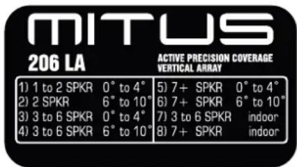
The preset to be chosen substantially depends on the system configuration, i.e. from the number of speakers in the array and the inclination of each one of them. The two last presets -called INDOOR- are expressly designed for usage in enclosed areas inside generally reverberating buildings.
-1 to 2 SPKR - 0 to 4^ : When the system is composed of one or two MITUS 206LA speakers and the angle between them (if they are two) is between 0^ and 4^ .
-2 SPKR - 6 to 10^ : When the system is composed of two MITUS 206LA speakers and the angle between them is between 6^ and 10^ .
-3 to 6 SPKR - 0 to 4^ : When the system is composed of three, four, five or six MITUS 206LA speakers and the angle between them is between 0^ and 4^ .
-3 to 6 SPKR - 6 to 10^ : When the system is composed of three, four, five or six MITUS 206LA speakers and the angle between them is between 6^ and 10^ . For example if the system is composed of six speakers in a J shaped array with the following angles between the speakers starting from the top: 0^ , 2^ , 4^ , 6^ , 8^ , then the first 4 speakers are configured with the '3 to 6 SPKR - 0 to 4^ ' preset, while the last two (with a 6^ and 8^ inclination) have to be configured with the '3 to 6 SPKR - 6 to 10^ ' preset.
-7+ SPKR - 0 to 4°: When the system is composed of 7 or more MITUS 206LA speakers and the angle between them is between 0° and 4°.
-7+ SPKR - 6 to 10^ : When the system is composed of 7 or more MITUS 206LA speakers and the angle between them is between 6^ and 10^ .
-3 to 6 SPKR - INDOOR: When the system is composed of three, four, five or six MITUS 206LA speakers regardless of the angle between them, and the system is used in reverberating rooms.
-7+ SPKR - INDOOR: When the system is composed of 7 or more MITUS 206LA speakers regardless of the angle between them, and the system is used in reverberating rooms.
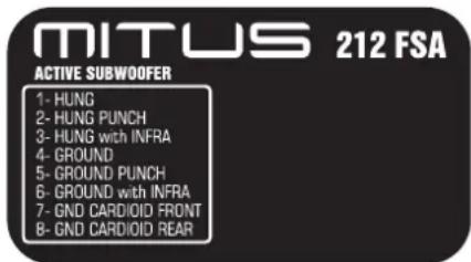
The preset selection depends on system configuration and type of desired sound. First of all it is necessary to choose the installation type between GROUND (laid on the ground or stage) and HUNG (flown over the MITUS 206LA or in an array of SUBs only). Then different equalization curves are to be associated to each one of these two installations in order to change the sound characteristics of the SUB.
-HUNG: Flown installation, default equalization curve, general purpose.
-HUNG PUNCH: Flow installation, the sound of the sub becomes drier, reduced low frequency extension but more energy concentrated in the 80-120Hz range.
-HUNG with INFRA: The system is composed of two different SUBs, MITUS 212FSA flow over
MITUS 206LA and MITUS 118SA or MITUS 121SA laid on the ground. This type of system is the most complete and suitable to reproduce sound in great events and over huge areas, most of all outdoor, since it permits obtaining a more even distribution of low frequency energy over the whole listening area. The MITUS 118SA/121SA SUB laid on the ground has to be configured with the INFRA preset.
-GROUND: Sub on the ground, default equalization curve, general purpose.
-
GROUND PUNCH: Sub on the ground, the sound of the sub becomes drier, reduced low frequency extension but more energy concentrated in the 80-120Hz range.
-
GROUND with INFRA: The system is composed of two different SUBs, MITUS 212/FSA flown over MITUS 118/SA MITUS 121/SA, all laid on the ground. This type of system is recommended when you want to use all the SUBs available in order to increase the SPL but the MITUS 212FSA cannot be flown. The MITUS 118SA/121SA SUB laid on the ground has to be configured with the INFRA preset.
-CARDIOID FRONT: Cardioid configuration, set this preset on the SUB oriented toward the audience
-CARDIOID REAR: Cardioid configuration, set this preset on the SUB oriented toward the stage (physically rotated 180^ with respect to the FRONT).
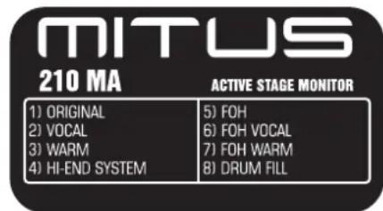
Since the speaker can be used both as stage monitor and general purpose speaker in Front Of House applications, presets are divided into 2 groups of 4 presets each. The first 4 presets are for stage monitor applications whereas the remaining 4 (called FOH) are to be used with the speaker installed on pole or truss stand and when the audience is not too close.
The description of the single presets is the same as that of models MITUS 112A and 115A, except for the DRUMFILL which is specially designed to monitor drummers, preferably in combination with a SUBWOOFER.
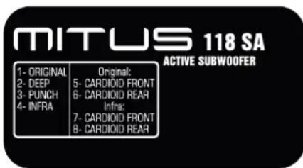
-ORIGINAL: Corresponds to the typical FBT sound. It is the default general purpose preset and is thus fit for the majority of applications.
-DEEP: This preset extends and emphasizes the low range of the subwoofer, for a very deep and soft sound suitable for high quality and medium energy applications, such as acoustic music, jazz, etc..
-PUNCH: the sound of the sub becomes drier, reduced low frequency extension but more energy concentrated in the 80-120Hz range. Suitable for rock music and high SPL applications
-INFRA: The filter is set to a lower frequency with respect to the other presets, thus only very low frequencies are reproduced. Choose this preset in systems where the MITUS 212FSA (set
with the 'with infra' preset) and MITUS 118/121SA subwooers are both present at the same time
ORIGINAL - below there are two presets for cardioid configuration with ORIGINAL equalization curve, i.e. by default suitable for general purpose
-CARDIOID FRONT: Cardioid configuration, set this preset on the SUB oriented toward the audience
-CARDIOID REAR: Cardioid configuration, set this preset on the SUB oriented toward the stage (physically rotated 180^ with respect to the FRONT).
- The system is composed of two different SUBs, MITUS 212/FSA and MITUS 118SA or MITUS 121SA, all laid on the ground. This type of system is recommended when you want to use all the SUBs available in order to increase the SPL but the MITUS 212FSA cannot be flown. The MITUS 118SA/121SASUB laid on the ground has to be configured with the INFRA preset.
INFRA - below there are two presets for cardioid configuration with INFRA equalization curve. Choose these presets in systems where the MITUS 212FSA (set with the 'with infra' preset) and MITUS 118/121SA subwoofoers are both present at the same time
-CARDIOID FRONT: Cardioid configuration, set this preset on the SUB oriented toward the audience
-CARDIOID REAR: Cardioid configuration, set this preset on the SUB oriented toward the stage (physically rotated 180^ with respect to the FRONT).
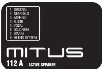
The presence of 8 DSP-managed presets permits to modify the speaker answer in a much more accurate way with respect to tune controls. Moreover, presets are already designed and optimized in an anechoic room to give the speaker the desired character.
-NEARFIELD: Suitable for a very close listening, up to 7-8m. Recommended for small rooms or with a very close audience where a medium-high SPL is anyway required.
-FARFIELD: For listening to the speaker at a distance over 15-20m. Suitable when the sound has to be projected over long distances.
-FLOOR: The speaker has specialized, and works as stage monitor. The answer is balanced to take into account the proximity to the floor and the listening of sounds in a near field.
-VOCAL: Permits obtaining top intelligibility of spoken language even in difficult environments or with high noise floor. The passband is modified to emphasize vocal range.
LOUDNESS: Typical answer curve for music application or record, with bass and treble
emphasized with respect to the middle frequencies that, instead, remain slightly in the background. This preset is very satisfying if listened to at low volume but is also suitable for using the speaker in discos and pubs.
-WARM; Gives a dense sound quality on middle-low frequencies and a less aggressive quality on trebles. Suitable for broadcasting music in very sound-absorbing environments or in situations that require a very strong sound at low frequencies and a sweet sound at middle-high frequencies.
- HI-END SYSTEM: It is characterized by the typical answer of top class speakers that are exclusively designed for touring applications. Therefore, very linear answer and passband without too much extension on the extremes. Those who are used to working with highly professional audio systems will find what they look for in this preset.
The lack of directivity at low frequencies is a problem affecting many sound reinforcement systems; this directivity can be controlled by lining up an array of direct radiation subwoofer according to patterns that concentrate diffused energy in one or more directions.
As for all frequency ranges, the sum of the energy of two subwoofoers can lead to both 6db sums and complete cancelling (when the sound waves are 180^ out of phase). The typical lobes of the polar diagram are caused by the difference in the time of arrival of sound sources to a specific position.
Cardioid configurations are useful to cancel low frequencies from the stage and consequently to improve critical microphone recordings.
The cardioid configuration enables a cardiod distribution of the SPL from Subwoofoers, reducing rear sound pressure.
It is perfect when the energy of low frequencies has to be attenuated, for example on the stage or in areas where it should be avoided due to noise pollution.
As you can see from the diagram, the attenuation achieved behind the front sound emission is 15-20 db approximately for the whole subwoofer operating range (30-130Hz)
Horiz.f=40Hz
Horiz. f = 80Hz normed to 1
H oriz. f = 130Hz normed to 1
For this purpose, a rear sub shall be employed every two front subs. The majority of the energy generated by the rear sub is used to cancel the energy of the other two front subs, so that the maximum overall SPL of the 3 subs in the front area is equal to +1db approximately compared to a typical (non cardioid) configuration with two front subs only.
Obviously, this configuration is valid also with a FRONT sub and a REAR sub.
Subs position is very important in order to obtain the best or possible rear attenuation. Use the configurations showed in figure.
Some presets of MITUS SUB range are specially dedicated to the cardioid configuration.
Set the CARDIOID FRONT preset in front SUBS, and in the SUB rotated by 180^ (hence, the rear sub) set the CARDIOID REAR preset.
Two different equalizations are available for the cardioid configurations of 118Sa and 121Sa subs: ORIGINAL and INFRA.
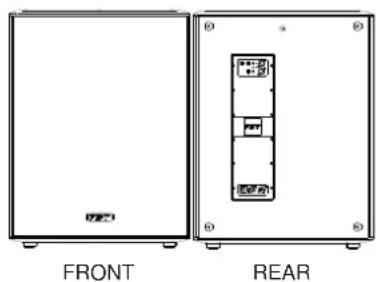
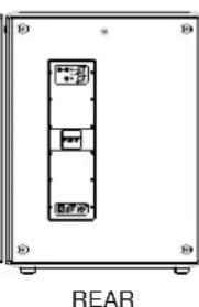
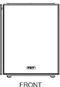

FRONT

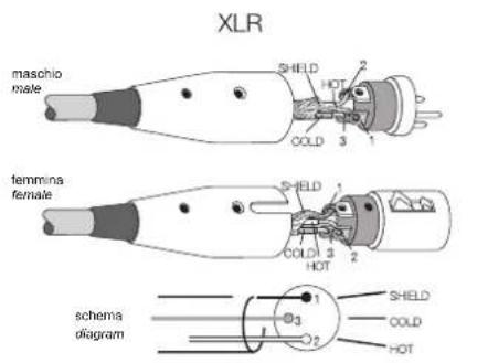
The 3-pole XLR connectors are almost always used for conducting mono-balanced signals; the three poles correspond respectively to ground (1), the positive signal (2) and the negative signal (3).
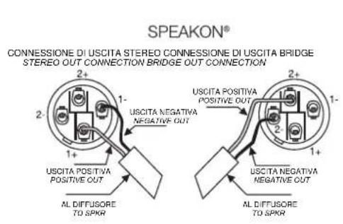
SPEAKON is a connector which is specially adapted for connecting power terminals to loudspeakers; when inserted in an appropriate socket it locks so as to prevent accidental disconnection; moreover, it is equipped with protection against electrical shocks and guarantees the correct polarisation.
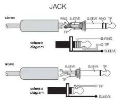
The JACKS are typical connectors for the transporting of two separate signals through two channels, left and right, using a single connector and therefore they can be either mono or stereo. Mono jacks (TS) also known as unbalanced jacks, are recognisable from stereo or balanced jacks (TRS) by their composition. The point of the mono jacks is divided into two parts, tip and ground Tip and Slave) to which the two poles are connected; the stereo or balanced jacks are divided in three parts, as they have a central ring (Ring) which is connected to a second wire, the third (negative) pole.

220-230V~
For its power supply the whole MITUS series features two NEUTRIK powercon three-pole outlets with locking connectors. Use the grey outlet for connecting several speakers with one another, and the blue one for supplying power to the system through the connector supplied.
CAUTION: the cable supplied can be used alone, and only if the total current absorption is lower than 16A (see example 1).
CAUTION: never replace the plug of the power cord supplied since the power cord can only support a maximum current of 16A (see example 1).
CAUTION: if the absorbed current exceeds 16A and is lower than 20A, a power cord has to be manufactured by specialized staff using a H05VV-F cable with 2.5 sq. mm section and plug with rated current > / = 20A where 20A is the maximum rated current of the powercon connector (see example 2).
- The power cord has to be assembled by specialized staff complying with national plant-engineering regulations.
- Protect the mains cable when it is not used.
In case of "chain connection" connect the cable to the grey outlet of the first speaker and to the blue outlet of the second one, and so on, making sure the maximum current indicated on the "AC LOOP OUTPUT" is not exceeded.
ATTENZIONE: PER SPEGNERE IL SISTEMA DISCONNETTERE PRIMA LA SPINA DELLA PRESA DI ALIMENTAZIONE RETE E DOPO IL CONNETTORE POWERCON CAUTION: TO SWITCH OFF THE SYSTEM DISCONNECT THE MAINS SUPPLY PLUG FIRST AND THEN THE POWERCON CONNECTOR

MAX.16A

MAX.20A

120V~
For its power supply the whole MITUS series features two NEUTRIK powercon three-pole outlets with locking connectors. Use the grey outlet for connecting several speakers with one another, and the blue one for supplying power to the system through the connector supplied.
CAUTION: If the total current demand does not exceed 12A, use the power cable supplied (see pic.1).
If the total current demand is between 12A and 18A, use the power cable AWG14SJT VW1 with plug rated current equal to 24A or lower (see pict. 2).
In both cases NEVER exceed the maximum current values shown in picture 1 and 2.
THE CABLE AND THE PLUG MUST HOLD THE UL OR CSA CERTIFICATION.
- The power cord has to be assembled by specialized staff complying with national plant-engineering regulations.
- Protect the main cable when it is not used.
- In case of "chain connection" connect the cable to the grey outlet of the first speaker and to the blue outlet of the second one, and so on, making sure the maximum current indicated on the "AC LOOP OUTPUT" is not exceeded.
ATTENZIONE: PER SPEGNERE IL SISTEMA DISCONNETTERE PRIMA LA SPINA DELLA PRESA DI ALIMENTAZIONE RETE E DOPO IL CONNETTORE POWERCON CAUTION: TO SWITCH OFF THE SYSTEM DISCONNECT THE MAINS SUPPLY PLUG FIRST AND THEN THE POWERCON CONNECTOR

MAX. 12A
NEMA 5-15P
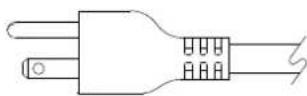
CAVO IN DOTAZIONE SUPPLIED CABLE CORD TYPE SJT3 x 14 VW1
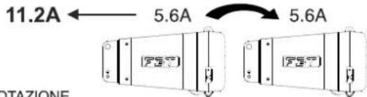

MAX.18A

MAX.2BOX
4000W continuous power
136dB @1mt
110dB @22mt
250mq. with 750 people
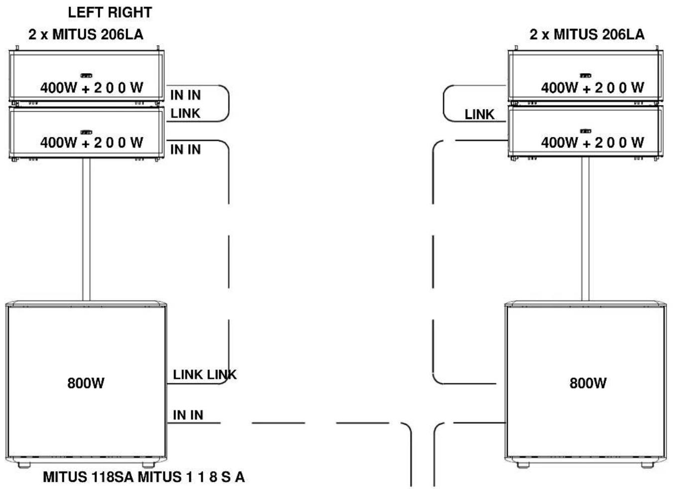
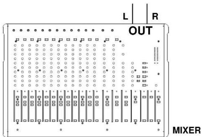
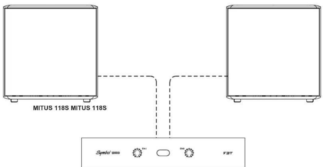
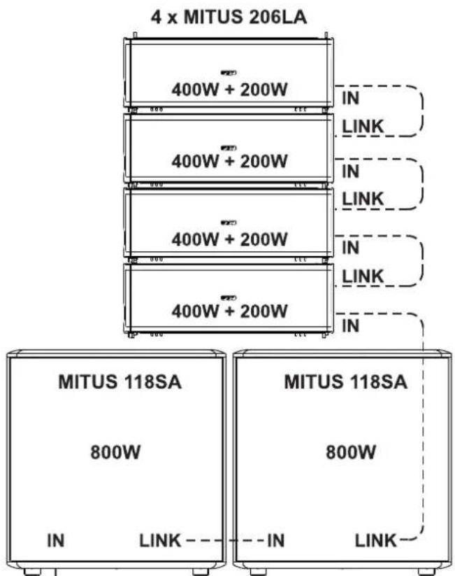
4 x MITUS 206L + 2 x MITUS 118S
The Bi-amp system requires a stereo amplifier; basically it is possible to connect the tweeter cables to one of the channels of the main amplifier and the woofer cables to the other one, thus guaranteeing high sound fidelity, higher dynamism and a significant SPL increase.
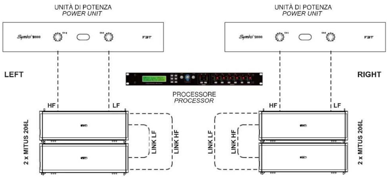
UNITÀ DI POTENZA
POWER UNIT
2 x MITUS 206L + 1 x MITUS 118S
8000W continuous power
142dB @1mt
110dB @44mt
950mq. with 2800 people
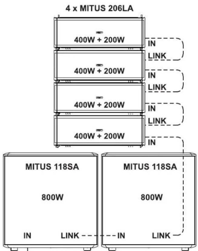
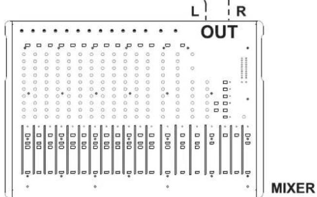
LEFT
RIGHT
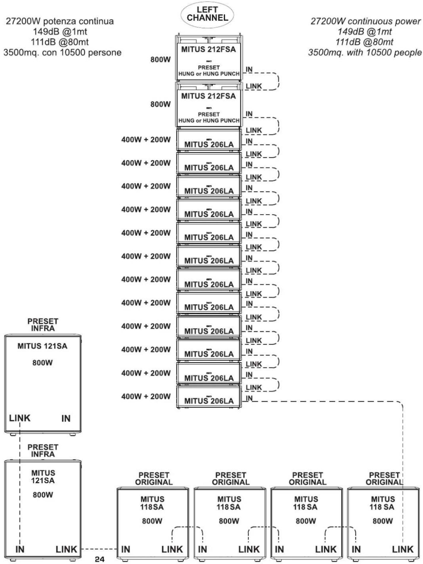
4 x MITUS 212 FSA + 24 x MITUS 206LA + 4 x MITUS 121SA + 8 x MITUS 118SA
C
BOTTOM
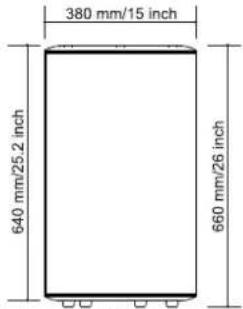
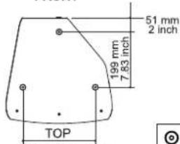
FRONT
260 mm/10.23 inch
112/112A
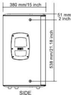
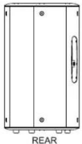

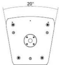
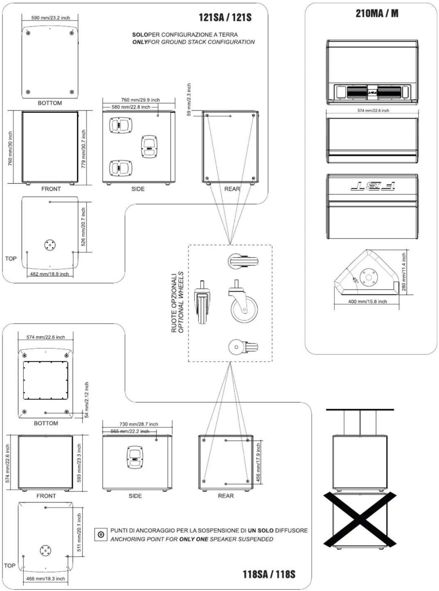
PUNTI DI ANCORAGGIO PER LA SOSPENSIONE DI UN SOLO DIFFUSORE ANCHORING POINT FOR ONLY ONE SPEAKER SUSPENDED
BOTTOM
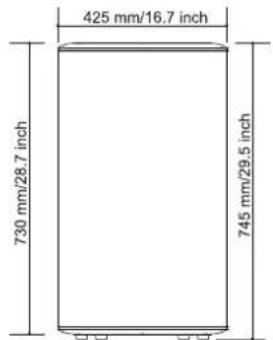
FRONT
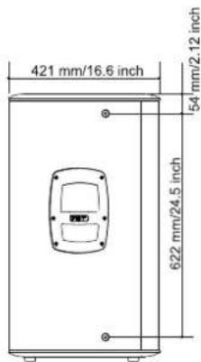
SIDE
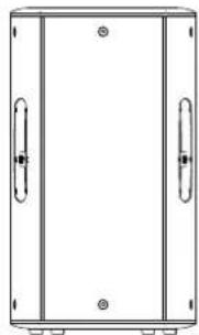
REAR
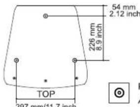
115/115A

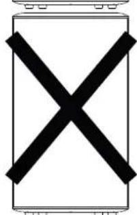
PUNTI DI ANCORAGGIO PER LA SOSPENSIONE DI UN SOLO DIFFUSORE ANCHORING POINT FOR ONLY ONE SPEAKER SUSPENDED
MITUS is the innovative true line array system with refined engineering and advanced technology. These are the qualities of a new speaker that defines the line array concept anew from the viewpoint of power, dimensions, light-weight, flexibility and ease of use. The possibility of combining 2 to 12/16 speaker modules permits using the system in a wide variety of situations, from the small band to the great open-air concert. The system features two 165mm custom made B&C neodymium magnet high excursion woofers with 44mm voice coil and a neodymium magnet B&C driver with 36mm exit throat and 64mm voice coil. The waveguide, optimized using the BEM finite element simulation method in order to minimise distortion, has 100^ horizontal dispersion. Designed to have optimal load on the driver diaphragm, it permits a plane sound wave propagation of up to over 18kHz in full compliance with the strictest physical criteria required for an ideal cylindrical wave source. The gas injection moulded polypropylene cabinet gives the system a very light weight. The cabinet-embedded hardware allows the suspension of 12 boxes with a 10:1 safety factor and an inclination of 0^ to 10^ with steps of 2^ . The 600+300W RMS PWM aluminium die cast amplifier module with switching power supply works also as a bearing structure for flying the units and permits adjusting the inclination angle. The digital signal processor with 8 presets permits an easy system configuration depending on curve and number of speakers available.
When low frequencies have to be extended, the MITUS 212FSA subwoofer perfectly complements the MITUS 206. Compact and capable of a very high SPL, in relation to the size, it features two 320mm custom made neodymium magnet B&C woofers with band-pass configuration. It can be flown over the line array or laid on the ground using the ground stacked system as a base.
To further extend and reinforce the low range SPL, it can perfectly work in pair with one of the other two MITUS series subwoofer (118 and 121), if the latter are set with the 'infra' preset.
The software permits to simulate the distribution of SPL and the frequency response in the listening area, thus being a valid instrument for designing the most suitable configuration for the environment needing sound reproduction.
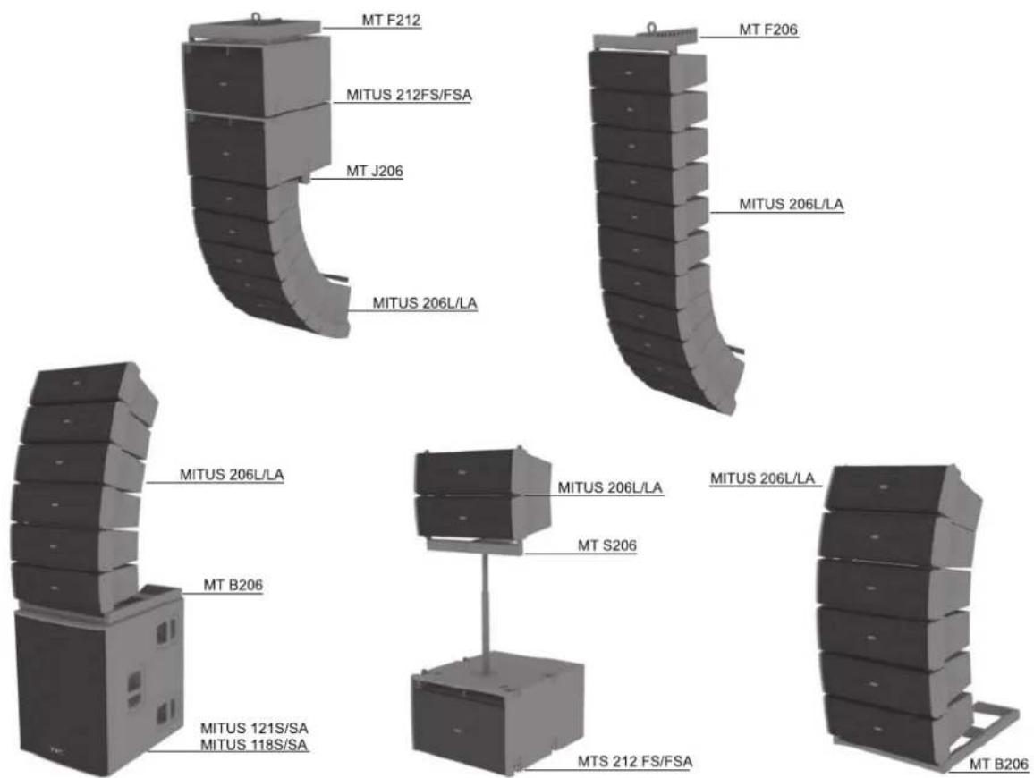
CONFIGURAZIONI CONSIGLIATE
RECOMMENDED CONFIGURATIONS
MITUS models feature a suspension system embedded in the bearing structure.
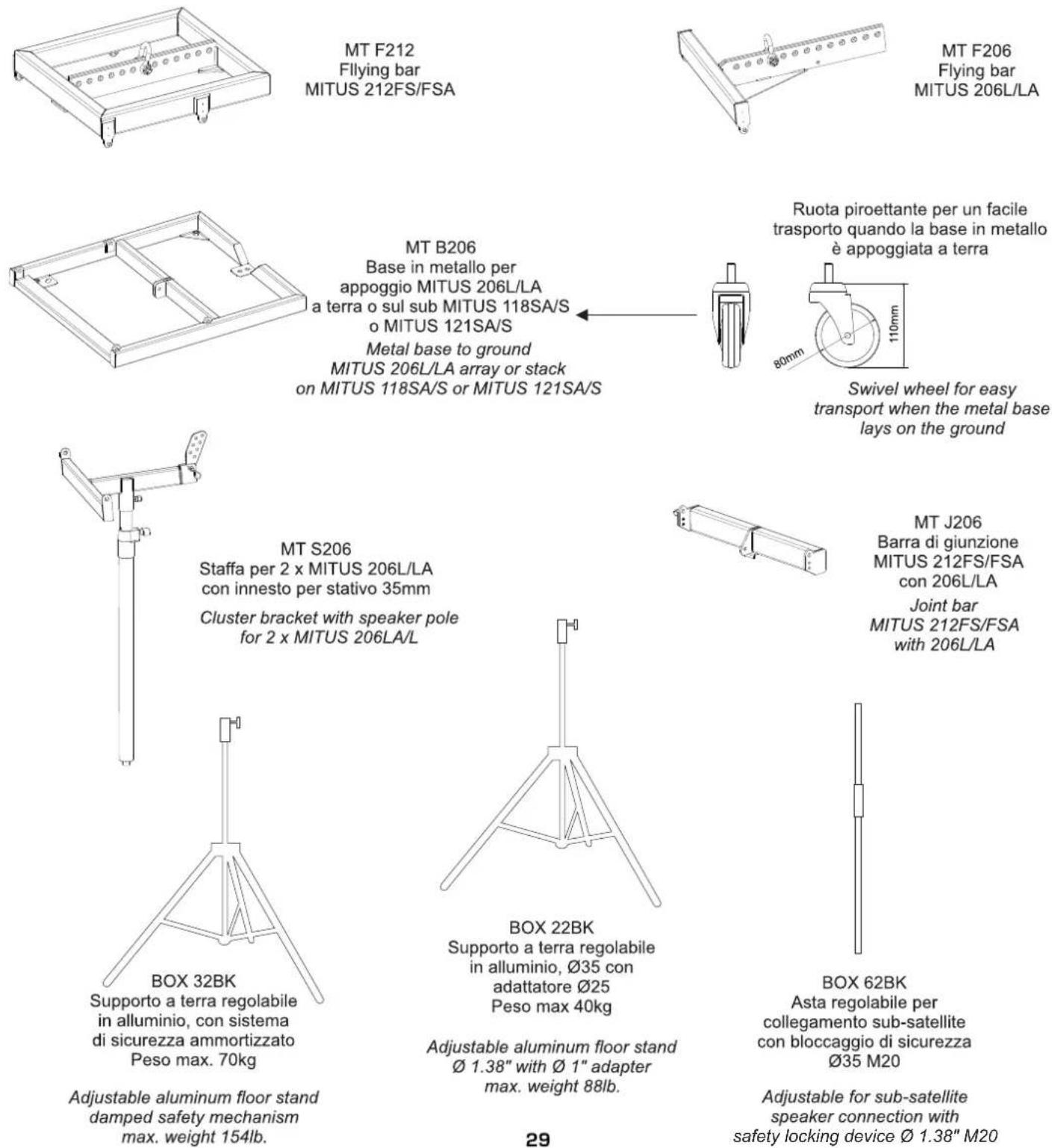
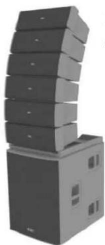
The only elements to be added (accessories) to realize complete arrays are: the MT F212 flybar for the configuration with subwoofer on top and the MT J206 joint bar between sub and satellite; the MT F206 flybar for configuration with satellites; the MT B206 metal base to ground satellites or to stack over the sub; the MT S206 cluster bracket to connect sub and 2 satellites.
CAUTION:
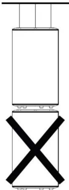
The use of different fixing accessories may cause a dangerous instability with possible damage to persons or things.
The configurations suggested by this manual were verified through computer modelling and operational testing; even in recommended configurations, before hanging any MITUS system check the relevant load limits.
Special attention was paid to the selection of materials and the manufacturing so as to permit high safety levels. The staff in charge of hanging the array system must be skilled and qualified; the installer/user will be responsible of ascertaining limits and lifting procedures for the structures to which the array will be attached.
An improper use of the array suspension system may cause major damage to persons and things.
Operations to be carried out:
Inspect the hanging material before every use
Observe all laws, and local and national regulations about safety of installations
Hang the system to the attachment points indicated in the manual
Use skilled staff only
Ensure all locking devices are perfectly fittedEnsure the capacity of lifting points and devices is greater than the load to be lifted.
Operations to be avoided:
Do not hang anything before reading the manual
Do not use unskilled staff
Never exceed load limits
Do not use non-original spare parts
Do not use damaged or worn materials
The MITUS system complies with the EN 60065 safety standard for audio, video and similar equipment.
The structure for hanging the system has a safety coefficient suitable for its use in compliance with the Machine Directive no. 459 DPR 24-7-1966 (Italian national implementation of the 89/392/EEC directive and subsequent modifications).
For the calculation of the safety coefficient for use and the regulatory framework relating to the design criteria for steel structures, the following reference technical standards were observed:
- EN 13814 - Fairground and Amusement Park machinery and structures. Safety Industry Standards.
-EN 1990-Basis of structural design. - EN 1991_4 Basis of structural design and action on structures. Basis of design.
- EN 1991_2_4 - Basis of structural design and action on structures. Action on structures. Wind actions.
-EN 1993_1_1-Design of steel structures. General rules and rules for buildings.
-EN 1993_1_8-Design of steel structures. Design of joints. - EN 1999_1_1_2007 Design of aluminium structures. General structural rules.
MITUS systems may be both flown and laid on the ground. System mounting type depends on the acoustic environment that needs being created and on the imposed assembly constraints. In the majority of common applications, it is better to hang the system since this guarantees a more homogeneous coverage of the listening area. Every time the area for sound reproduction is located at a single level below an available attachment point and extends over a certain length, system suspension is the best solution because it permits to better distribute the sound pressure over the whole area where sound is reproduced.
The pictures in this page show the array configurations allowed to meet the maximum weight and angle safety parameters relating to a 10:1 safety factor.
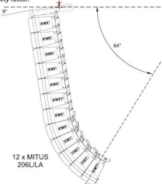
Should you need to hang a system whose size is greater than the allowed one shown in the pictures, you will be allowed to do it, but you must check that the suspension system safety requirements provided for by the current regulations of the country of installation are met. This check shall be carried out by the person responsible for the flying structure.
FBT accepts no responsibility for any damage to people or objects if these instructions are not complied with or if the safety factor of all elements related to system suspension are not properly checked.
FBT will also place at your disposal a software called MITUS206_flying, which helps calculating the safety factor of the weakest point of MITUS206L/LA-MITUS212FS/FSA unit suspension system according to the used configuration.
Follow these steps for a correct installation:
- Use the EASE FOCUS software with MITUS 206 database to simulate the configuration suitable for the environment where the sound is to be reproduced considering SPL intensity and distribution in the audience
- With the mechanical configuration parameters obtained, calculate the safety factor of MITUS 206/MITUS 212 unit suspension system using the MITUS206_flying software
- Check that the safety factor calculated falls within the range allowed by the standards and safety regulations in force in the country of installation.
Should the safety factor be lower or incompatible with the one required by current regulations, the installation is not allowed. Therefore, system size or inclination angles have to be changed, and sound simulation and safety checks are to be carried out again.
For further information on the use of the EASE FOCUS and MITUS206_flying software please refer to the software help menu or to the help information you will find on software websites.
It is a software that permits an accurate simulation of the mechanical and acoustic behaviour of the MITUS series line array system.
The simulation algorithm is based on measurements taken on single modules; it is possible to set the number of areas for sound reproduction, the number of speakers, angles and levels relating to speakers and simulation parameters. It is also possible to check the attachment position of the flybar and the anchoring points of the system in relation to the maximum loads allowed.
The software is an instrument that allows to immediately choose the best system configuration and proves suitable for both the experienced installer and the less experienced user thanks to its automatic calculation feature.
The software is available for download at FBT's website: www.fbt.it
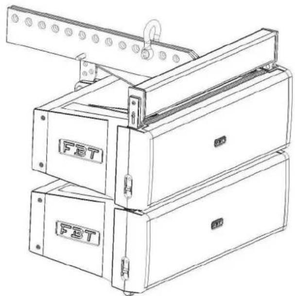
AGGANCIO DI 2 SATELLITI CON BARRA DI SOSPENSIONE
ATTACHMENT OF 2 SATELLITES WITH FLYBAR
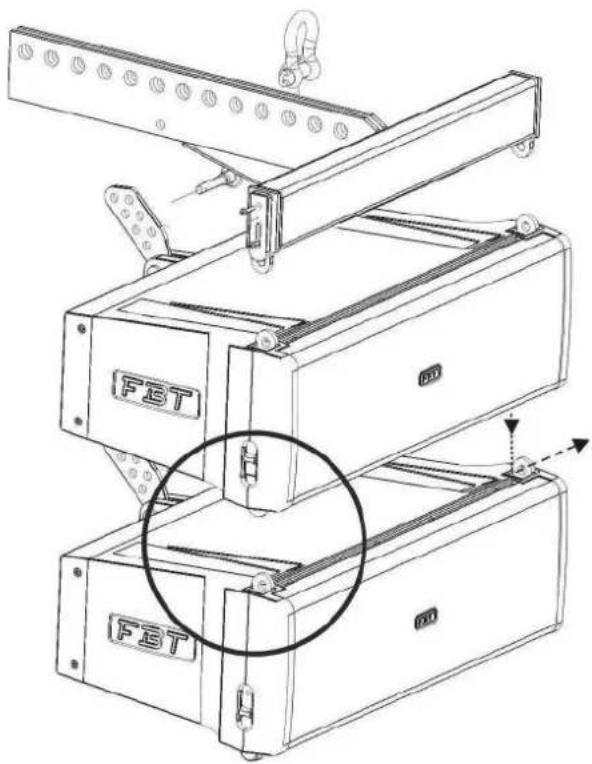
1
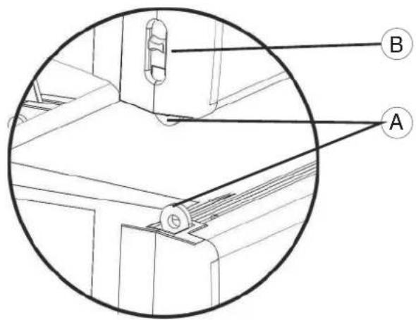
IL FISSAGGIO ANTERIORE TRA DUE SATELLITI AVVIENE SEMPLICENTE TRAMITE AGGANCIO PERNO-FORO (A).
VERIFICARE LO SCATTO DELLA MOLLA DI SICUREZZA(B)
THE FRONT FIXING BETWEEN TWO SATELLITES IS CARRIED OUT BY A SIMPLE PIN IN HOLE METHOD (A).
CHECK THAT THE SAFETY SPRING HAS SNAPPED (B)
2
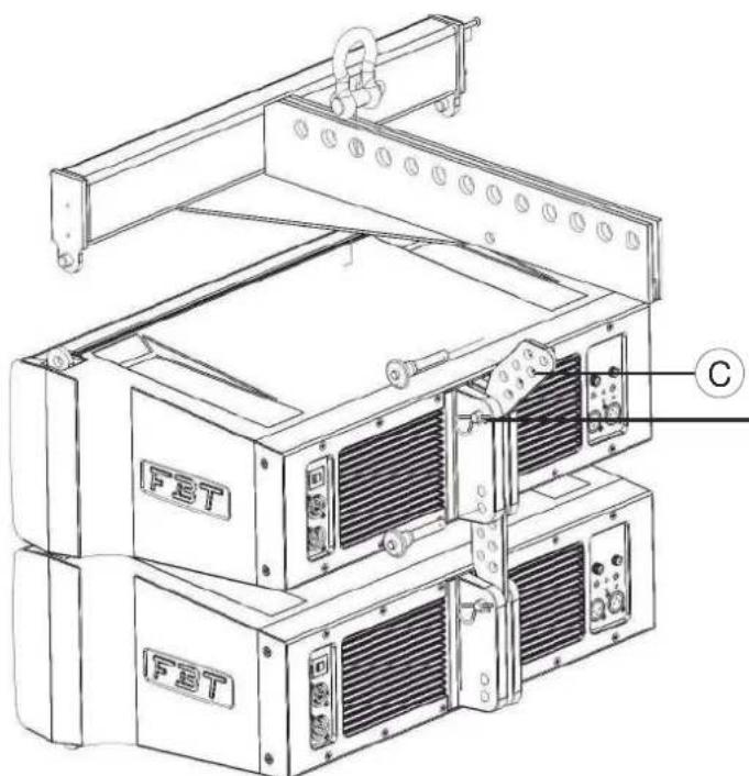
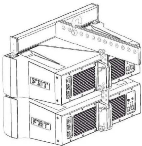
PER IL FISSAGGIO POSTERiore DEI SATELLITI UTILIZZARE LA BARRA DI CONNECTION IN DOTAzione.
FISSARE IL PRIMO SATELLITE ALLA BARRA DI SOSPENSIONE UTILIZZANDO IL FORO (C) DELLA BARRADI CONNECTION
USE THE CONNECTION BAR SUPPLIED FOR THE REAR CONNECTION OF SATELLITES.
FIX THE FIRST SATELLITE TO THE FLYBAR BY USING THE HOLE (C) OF THE JOINT BAR.
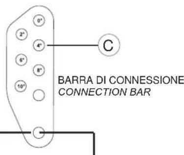
Hole for fixing the joint bar through cheese head pin with split pin.
AGGANCIO DI 2 SATELLITI CON BARRA DI SOSPENSIONE
ATTACHMENT OF 2 SATELLITES WITH FLYBAR
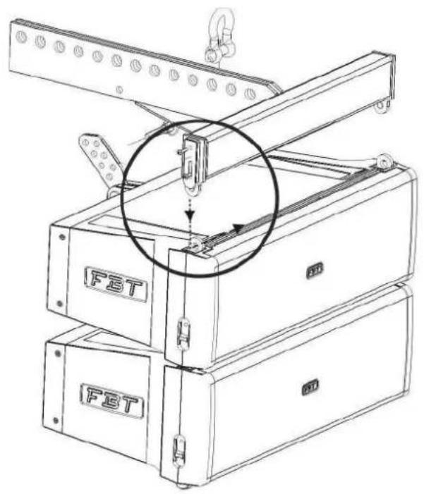

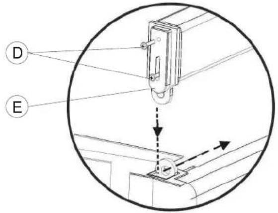
PER IL FISSAGGIO ANTERIORE TRA SATELLITE E BARRA DI SOSPENSIONE TOGLIERE LA STAFFA DI SICUREZZA (E) TRAMITE LE VITI AD ALETTA (D) E AGGANCIARE TRAMITE PERNO-FORO.
RIPOsIZIONARE LA STAFFA DI SICUREZZA E FISSARELEVITI.
FOR THE FRONT FIXING OF SATELLITE AND FLYBAR REMOVE THE SAFETY BRACKET (E) THROUGH THE BUTTERFLY SCREWS (D) THEN LOCK THE PIN INTO THE HOLE.
REPLACE THE SAFETY BAR AND SECURE THE BUTTERFLY SCREWS FOR FIXING.
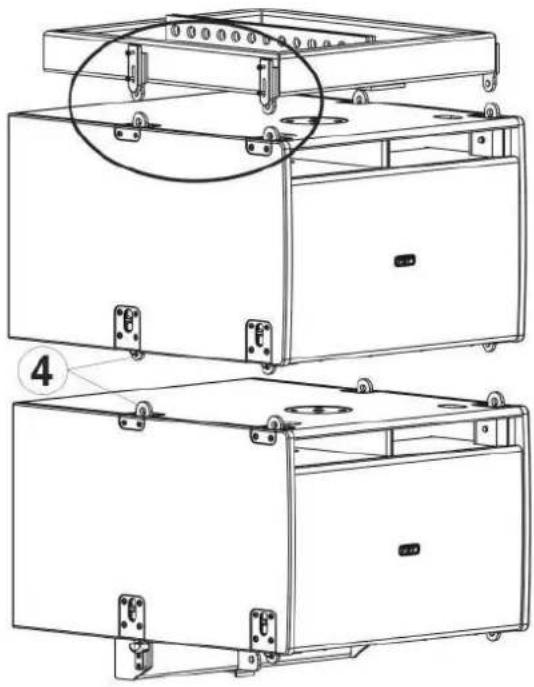
AGGANCIO DI 2 SUBWOOFER, SATELLITE E BARRA DI SOSPENSIONE ATTACHMENT OF 2 SUBWOOFERS, SATELLITE AND FLYBAR
I DUE SUBWOOFERS VANNO AGGANCIATI SEGUENDO LA STESSA PROCEDURA DESCRITTAT PRECEDENTEMENTE PER I SATELLITI.
5
ATTACH THE TWO SUBWOOFERS BY FOLLOWING THE SAME PROCEDURE DESCRIBED ABOVE FOR SATELLITES
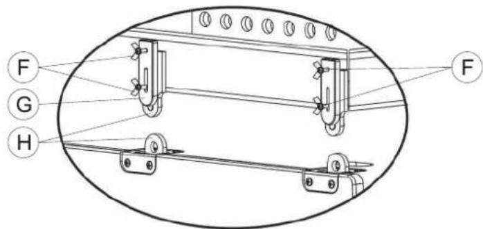
PER FISSARE LA BARRA DI SOSPENSIONE AL PRIMO SUBWOOFER TOGLIERE LE 4 VITI AD ALETTA (F) E LA RELATIVA STAFFA DI SICUREZZA (G); PROCEDURE ALL'AGGANCIO PERNO-FORO (H) E FISSARE NUOVAMENTE LE STAFFE DI SICUREZZAELEVITI(F).
TO FIX THE FLYBAR TO THE FIRST SUBWOOFER REMOVE THE 4 BUTTERFLY SCREWS (F) AND THE RELEVANT SAFETY BRACKET (G); LOCK THE PIN INTO THE HOLE (H) THEN FIX THE SAFETY BRACKETS AND THE SCREWS (F) BACK.
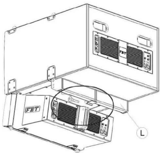
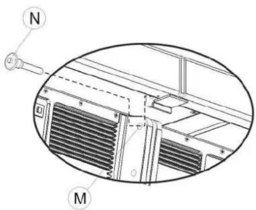
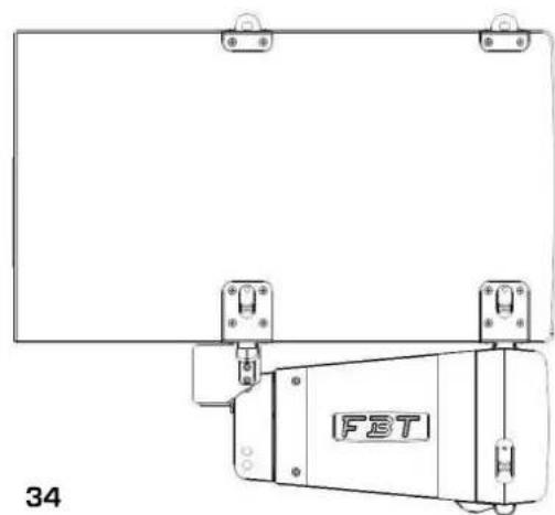
IL PRIMO SATELLITE VA AGGANCIATO CON IL SUBWOOFER PER MEZZO DELLA BARRA DI GIUNZIONE (L); UTILIZZARE IL FORO (M) E IL PERNOATESTACILINDRICA(N).

THE FIRST SATELLITE HAS TO BE ATTACHED TO THE SUBWOOFER THROUGH THE JOINT BAR (L); USE THE HOLE (M) AND THE CHEESE HEAD PIN (N).

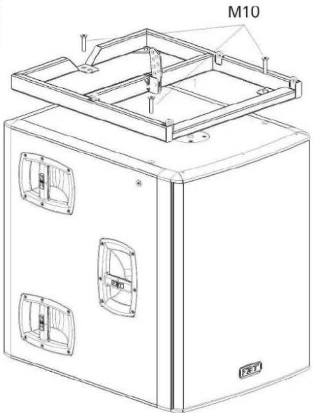
1) TOGLIERE DALLA PARTE SUPERIORDEL SUBWOOFERLETREVITIM10 2) COLLOCARE, COME DA FIGURA, LA BASE IN METALLO MT B206 SOPRA IL BOX E FISSARLA TRAMITE ALTRE VITIN DOTAZIONC CON L'ACCESSORIO (NON USARE LE VITI PRECEDENTEMENTETOLTEDALBOX)
1) REMOVE THE THREE M10 SCREWS FROM THE TOP OF THE SUBWOOFER. 2) PLACE THE MT B206 METAL BASE ON THE BOX, AS SHOWN IN THE PICTURE, AND FIX IT WITH OTHER THREE SCREWS SUPPLIED WITH THE ACCESSORIES (DO NOT USE THE SCREWS FORMERLY REMOVED FROM THE BOX).
2
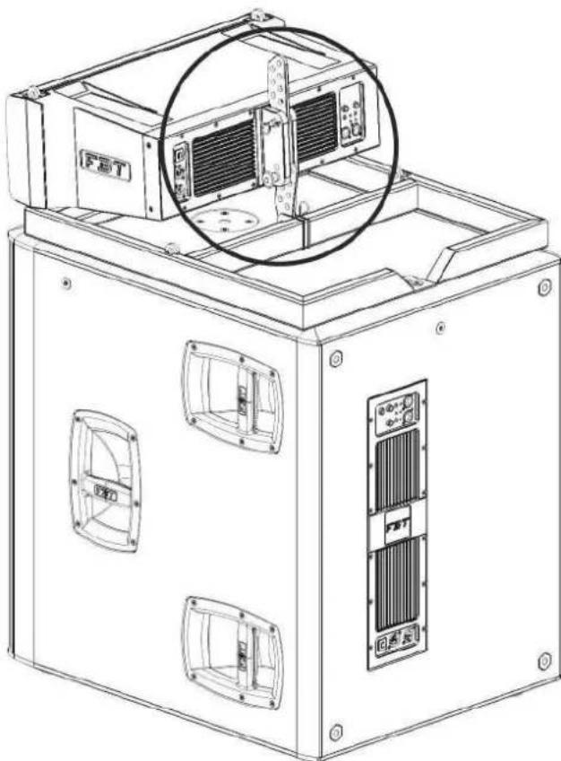
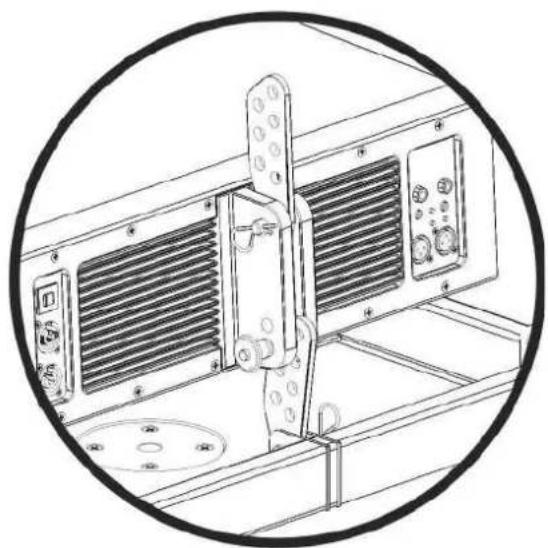
PER AGGANCIARE POSTERIORMENTE IL SATELLITE ALLA BASE IN METALLO UTILIZZARE LA BARRA DI CONNECTION ( USARE QUELLA INUTILIZZATADEL PRIMO SATELLITE INALTO).
USE THE JOINT BAR FOR THE REAR CONNECTION OF THE SATELLITE TO THE METAL BASE (USE THE CONNECTION BAR THAT IS NOT USED FOR THE FIRST SATELLITE ON TOP).
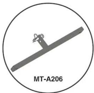
QUESTO ACCESSORIO VA MONTATO SULL'ULTIMO DIFFUSORE AGGANCIATO PER ASSICURARE TUTTO IL SISTEMA MEDIANTE FUNI ED EVITARNE LAROTAZIONE EL'OSCILLAZIONE.
MOUNT THIS ACCESSORY ON THE LAST SPEAKER HOOKED IN ORDER TO SECURE THE WHOLE SYSTEM BY MEANS OF ROPES AND PREVENT IT FROM ROTATING AND OSCILLATING.
| MODEL | 206LA | 212FSA | 118SA | 121SA | 112A | 115A | 210MA | ||
| Configuration | way | 2 1 1 | 2 2 2 | ||||||
| Built-in amplifiers cont. RMS LF/HF | W | 400/200 800 | 800 800 400/200 | 400/200 400/200 | |||||
| Built-in amplifiers max. RMS LF/HF | W | 600/300 | 1200 1200 | 1200 | 600/300 | 600 | 300 600/300 | ||
| Built-in amplifiers max. peak LF/HF | W | 1200/600 | 2400 2400 | 2400 | 1200/600 | 1200 | 600 1200/600 | ||
| Frequency response | @-6dB | 68Hz-20kHz | 45Hz-120Hz | 36Hz-100Hz | 29Hz-100Hz | 50Hz-20kHz | 46Hz-20kHz | 60Hz-20kHz | |
| Low frequency woofer | inch | 2x6.5 | 2x12 | 1x18 | 1x21 | 1x12 | 1x15 | 2x10 | |
| 1.7 coil | 3 coil | 3 coil | 4.5 coil | 3 coil | 3 coil | 2.5 coil | |||
| High frequency driver | inch | 1x1.4 | 1x1 | 1x1 | 1x1.4 | ||||
| 2.5 coil | 1.7 coil | 1.7 coil | 2.5 coil | ||||||
| Max SPL cont/peak | dB | 125/134 | 134/138 half space | 135/139 half space | 133/137 half space | 126/133 | 127 | 133 | 127/134 |
| Dispersion | H x V | 100° x 10° max (dependant upon n. of elements) | omnidirectional | omnidirectional | omnidirectional | 80° x 50° | 80° x 50° | 70° conical | |
| Input impedance | kOhm | 22 | 22 | 22 | 22 | 22 | 22 | 22 | |
| Crossover frequency | kHz | 1.2 | preset dependant | preset dependant | preset dependant | 1.5 | 1.5 | 1.2 | |
| AC power requirement | VA | 640 | 640 | 640 | 640 | 640 | 640 | 640 | |
| Input connectors | XLR with loop | XLR with loop | XLR with loop | XLR with loop | XLR with loop | XLR with loop | XLR with loop | ||
| Power cord | ft | 16.40 | 16.40 | 16.40 | 16.40 | 16.40 | 16.40 | 16.40 | |
| Net dimensions (WxHxD) | inch | 22.6x8.7x15.1 | 22.6x16.5x26 | 22.6x23.4x28.7 | 23.2x30.7x29.9 | 15x26x15 | 16.7x29.5x16.6 | 22.6x11.4x15.8 | |
| Net weight | lb. | 30.8 | 80.5 | 103.6 | 127.8 | 45 | 61.7 | 41.9 | |
| Transport dimensions (WxHxD) | inch | 25.98x11.02x18.11 | 30.9x20.47x27.95 | 30.7x29.92x25.19 | 31.49x37x27.55 | 19.29x29.52x19.29 | 22.04x33.85x21.65 | 26.57x15.55x20.07 | |
| Transport weight | lb. | 34.6 | 90.4 123.9 | 146.6 | 48.5 | 67.3 | 46.5 |
| MODEL | 206L | 212FS | 118S | 121S | 112 | 115 | 210M | |
| Configuration | way | 2 1 1 | 2 2 2 | |||||
| Recommended amplifier | W rms | 500 LF/150 HF | 1000 | 1000 | 2000 | 700 | 800 800 | |
| Long term power * | W | 250 LF/70 HF | 500 600 | 1000 | 350 | 400 400 | ||
| Short term power (IEC 268-5) | W | 1000 LF/300 HF | 2000 2000 | 3600 | 1200 | 1400 | 1600 | |
| Frequency response | @-6dB | 75Hz-20kHz | 50Hz-250Hz | 36Hz-200Hz | 29Hz-250Hz | 55Hz-18kHz | 50Hz-18kHz | 65Hz-18kHz |
| Low frequency woofer | inch | 2x6.5 | 2x12 | 1x18 | 1x21 | 1x12 | 1x15 | 2x10 |
| 1.7 coil | 3 coil | 3 coil | 4.5 coil | 3 coil | 3 coil | 2.5 coil | ||
| High frequency driver | inch | 1x1.4 | 1x1 | 1x1 | 1x1.4 | |||
| 2.5 coil | 1.7 coil | 1.7 coil | 2.5 coil | |||||
| Sensitivity (@1W, 1m) | dB | 97 LF/108 HF | 99 | 101 | 99 | 99 | 100 | 100 |
| Max SPL cont/peak | dB | 125/129 LF | 134/138 | 135/138 | 136/139 | 127/131 | 128/132 | 128/132 |
| 129/133 HF | half space | half space | half space | |||||
| Dispersion | H x V | 100° x 10° max (dependant upon n. of elements) | omnidirectional | omnidirectional | omnidirectional | 80° x 50° | 80° x 50° | 70° conical |
| Nominal impedance | Ohm | 16 LF/16 HF | 8 | 4 4 | 8 LF/HF | 8 LF/HF | 4 LF/HF | |
| Crossover frequency | kHz | 1.2 | ext. active filter | ext. active filter | ext. active filter | 1.5 | 1.5 | 1.2 |
| Recommended HP filter | 65Hz-24dB oct. | 40Hz-24dB oct. | 32Hz-24dB oct. | 25Hz-24dB oct. | 40Hz-24dB oct. | 40Hz-24dB oct. | 50Hz-24dB oct. | |
| Recommended ext. filter | digital management with FBT preset | digital management with FBT preset | digital management with FBT preset | digital management with FBT preset | ||||
| Input connectors | 2xSpeakon NL4 in & throu | 2xSpeakon NL4 in & throu | 2xSpeakon NL4 in & throu | 2xSpeakon NL4 in & throu | 2xSpeakon NL4 in & throu | 2xSpeakon NL4 in & throu | 2xSpeakon NL4 in & throu | |
| Net dimensions (WxHxD) | inch | 22.6x8.7x15.1 | 22.6x16.5x26 | 22.6x23.4x28.7 | 23.2x30.7x29.9 | 15x26x15 | 16.7x29.5x16.6 | 22.6x11.4x15.8 |
| Net weight | lb. | 29.8 | 77.2 | 99.2 | 123.5 | 39.7 | 57.3 | 37.5 |
| Transport dimensions (WxHxD) | inch | 25.98x11.02x18.11 | 30.9x20.47x27.95 | 30.7x29.92x25.19 | 31.49x37x27.55 | 19.29x29.52x19.29 | 22.04x33.85x21.65 | 26.57x15.55x20.07 |
| Transport weight | lb. | 33.5 | 87 | 119.5 | 142.2 | 44.1 | 62.8 | 42.1 |
All speakers are tested with a 6dB crest factor, where the ratio between the average voltage and the pulse voltage supplied to the system exceeds or equals 2; FBT recommends using an amplifier with an RMS power that doubles the long term power so as to wholly preserve the dynamics of the speakers and guarantee the integrity of the music signal.
CAUTION: This does not guarantee the speakers preservation in any condition of use. In the presence of a highly compressed music program or if the amplifier is driven into clipping, the speakers may suffer damage due to overtemperature or excessive excursion.
For music programs with low dynamics and high distortion it is recommended to use an amplifier with a RMS power that is equal or below the power specified in the table so as not to exceed the heat dissipation capacity of the speakers. In any case driving the amplifier into clipping causes a great increase of the power supplied to the driver which in turn could suffer damage in spite of the intervention of the cx-over protection.
ALIMENTATORE SWITCHING
A unit that, before making the power available for internal use in the amplifier, converts the AC power supply into a much higher frequency thanks to a switch mode circuit. The advantages of a switch mode power supply are its lower weight and reduced electromagnetic emissions.
BAND-PASS (band-pass filter)
This is a device that, once given a centre frequency and a bandwidth, lets only the frequencies within the band specified by these parameters pass, attenuating the others.
BANDWIDTH
The bandwidth, for example an operating parameter of the band-pass filter.
AMPLIFIERCLASS
Power amplifiers are mainly classified according to the type of output stage. Such classification is based on how long output devices remain active during each cycle. The most common classes of professional sound amplifiers are: AB, AB+B, D, G, H.
CLIPPING
Digital distortion occurring when the amplitude of an input signal to a sampling device exceeds the dynamic range that the same device can manage.
COMPRESSOR
A device reducing the dynamic range of an audio signal. First, the threshold has to be set. Then, if the signal exceeds the threshold value, its gain is reduced.
CROSSOVER network
High- and low-pass filters used for speakers do not cut-off undesired frequencies; the roll-off (filter attenuation) occurs over a number of octaves. Common filter slope for speakers are 1^st through 4^th order, corresponding to 6dB/octave to 24 dB/octave.
DAMPING FACTOR
The damping factor is generally conceived of as an indicator of how much "sustained" the sound of a sub speaker dedicated amplifier will be. The peaker main element is a voice coil, mounted in a magnetic field; while the coil moves within the magnetic field, voltage is induced through it; if speaker resonant modes are not properly controlled by the amplifier, speaker output low sounds may be too "reverberating". As far as its measurement is concerned, the damping factor is the ratio between speaker impedance and amplifier output impedance.
DYNAMICS, dynamic range
The dynamic range of a sound is the ratio between the strong and powerful part of that sound, and its soft and light part; it is measured in dB.
PHASE
Considering given waves with different waveforms and frequencies, they are told to be "in phase" if they cross the time axis with the same slope at the same time. Otherwise, they are told to be "out-of-phase". The phase is a very important element of sound waves since it is essential to establish the result of the addition of several waves; for instance, two identical sounds with opposite phases cancel out.
CUT OFF FREQUENCY
Frequency set as operating parameter in a low- or high-pass filter.
HIGH PASS FILTER
It is a filter letting the frequencies above a certain threshold pass, and cutting the frequencies below such threshold. It is also called "low-cut filter".
LIMITER
It is special compressor designed to prevent the signal from exceeding a certain amplitude level.
WAVELENGTH
In the transmission medium, the distance between the beginning and the end of a cycle; it depends on speed and frequency (L = v/f where L = length, v = speed and f = frequency).
OVERLOAD
Distortion occurring when the signal applied exceeds the maximum input level of the device.
PINK NOISE
The noise is said to be pink, as opposed to the white noise. It is a non periodic noise, which includes frequencies from the whole acoustic spectrum. However, unlike the white noise, it has higher amplitude at low frequencies, and lower amplitude at high frequencies, so to adjust to the human ear sensitivity, that is less sensitive to lower frequencies.
FREQUENCYRESPONSE
The frequency response is the actual frequency range a device can play.
RMS
Root Mean Square: it is a value expressing the significant mean of the amplitude values of a sound wave.
SPL
Perceived sound volume or pressure, measured in decibels. The SPL is a function of signal amplitude.
THD
The ratio between the power of the fundamental tone at device output and the total power of all the harmonics in the frequency band at device output.
SAFETYFACTOR
Ratio between the breaking load of the suspension system and the real weight of the structure
ATTENTION-PRECAUTION 1
WARNHINWEISE-VORSICHTSMABNAHMEN
ACCESSIONES 29
ZUBEHÖR
GUIDE AU MONTAGE DU SYSTÉME ARRAY VERTICAL 30-31-32-33-34-35
MONTAGEANLEITUNG DES SYSTEMS IN VERTIKAL ARRAY
CARACTERISTIQUES TECHNIQUES 36-37
TECHNISCHE DATEN
GLOSSAIRE 38-39
WÖRTERVERZEICHNIS
POUR EVITER LE RISQUE DE CHOC ELECTRIQUE NE PAS OUVRIR LE COUVERCLE
NE PAS UTILISER D'OUTILS MECANIQUES A L'INTÉRIEUR CONTACTER UN CENTRE D'ASSISTANCE QUALIFIÉ
POUR EVITER LE RISQUE D'INCENDIE OU DE CHOC ELECTRIQUE NE PAS EXPOSER L'APPAREILLAGE A LA PLUIE OU A L'HUMIDIT

CE SYMBOLE PRÉVIENT, LA OU ILAPPARAIT, DE LAPRÉSENCE D'UNE TENSION DANGEREUSE NON ISOLEÉ A L'INTÉRIEUR DE LA CAISSE : LE VOLTAGE PEUT ÉTRE SUFFISANT POUR REprésentER UN RISQUE DE DECHARGES ÉLECTRIQUES.

CE SYMBOLE PRÉVIENT, LA OU IL APPARAIT, DE LA PRESENCE D'IMPORTANTES NOTICES DE MODE D'EMPLOI ET CONCERNANT L'ENTRETIEN DANS LA DOCUMENTATION JOINTE. VEUILLEZ CONSULTER LE MODE D'EMPLOYE.
INFORMATIONS DE SECURITE IMPORTANTES
Sound Reinforcement Stage Monitor
1

30^ ---- with 50^ horn position
50^ ---- with 80^ horn position
80^ ---- total coverage with 50^ horn position
130^ ---- total coverage with 80^ horn position
FRONT OF HOUSE
STAGE MONITOR
121SA/118SA
OVERLOAD (surcharge)
WARNING: where affixed on the equipment or package, the barred waste bin sign indicates that the product must be separated from other waste at the end of its working life for disposal. At the end of use, the user must deliver the product to a suitable recycling centre or return it to the dealer when purchasing a new product. Adequate disposal of the decommissioned equipment for recycling, treatment and environmentally compatible disposal contributes in preventing potentially negative effects on the environment and health and promotes the reuse and/or recycling of equipment materials. Abusive product disposal by the user is punishable by law with administrative sanctions.
All informations included in this operating manual have been scrupulously controlled; however FBT is not responsible for eventual mistakes. FBT Elettronica SpA has the right to amend products and specifications without notice.