
EBM 352/3 - Drill Eibenstock - Free user manual and instructions
Find the device manual for free EBM 352/3 Eibenstock in PDF.

| Product Type | Water-cooled diamond core drill |
| Brand | Eibenstock |
| Model | EBM 352/3 |
| Rated Voltage | 230 V ~ |
| Power Consumption | 3000 W |
| Rated Current | 13.5 A |
| Frequency | 50-60 Hz |
| Max Drilling Diameter | 352 mm |
| Tool Holder | 1 1/4" UNC |
| Insulation Class | Class I (double insulation) |
| Protection Rating | IP20 |
| Weight | 12.5 kg |
| Speeds | 3 mechanical speeds: 230, 500, 1030 rpm |
| Overload Protection | Torque limiter, electronic and thermal protection |
| Safety System | PRCD switch, automatic brush stop |
| Intended Use | Drilling concrete, stone, block with water, mounting on support |
| Included Accessories | Ball valve, Gardena connector, PRCD, wrenches SW32 and SW41, instruction manual |
| Maintenance | Change motor oil every 150 h, check brushes every 200 h |
| Required Safety Equipment | Goggles, ear protection, mask, gloves, safety shoes, hard hat |
| Certifications | CE according to EN 61029, EN 55014, EN 61000 |
Frequently Asked Questions - EBM 352/3 Eibenstock
User questions about EBM 352/3 Eibenstock
0 question about this device. Answer the ones you know or ask your own.
Ask a new question about this device
Download the instructions for your Drill in PDF format for free! Find your manual EBM 352/3 - Eibenstock and take your electronic device back in hand. On this page are published all the documents necessary for the use of your device. EBM 352/3 by Eibenstock.
USER MANUAL EBM 352/3 Eibenstock
Original Instructions....18 - 31
Notice originale ....32 - 44
natural_image
EIBENSTOCK electric drill tool with green and black casing, no visible text or symbols on bodyDeutsch
Wichtige Hinweise
natural_image
Close-up of a black and green industrial vacuum cleaner with a white arrow pointing to the handle (no visible text or symbols)natural_image
Close-up of a green circular button with numbered labels (1, 2, 3) on a black background, no readable text or symbols beyond labels.natural_image
Simple line drawing of a trash bin with no text or symbolsNur für EU-Länder
natural_image
Close-up of a mechanical component with two circular holes and a white arrow pointing to a feature (no text or symbols visible)Frank Markert
Head of Engineering
English
Important Instructions
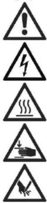
Important instructions and warning notices are allegorized on the machine by means of symbols:


Before you start working, read the operating instructions of the machine.
Work concentrated and carefully. Keep your work-place clean and avoid dangerous situations.
In order to protect the user, take precautions.
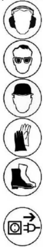
During work you should wear ear protectors, goggles, dust mask, protective gloves and sturdy work clothes!


Wear safety goggles
Wear safety helmet
Use ear protection
Wear protective gloves
Wear protective boots
Warning notices:


Warning of general danger
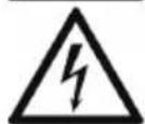
Warning of dangerous voltage
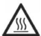
Warning of hot surface
Danger of being ripped or cut
Technical Data
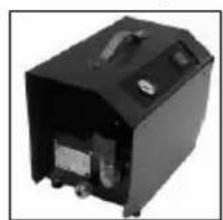
Wet Diamond Core Drill Motor EBM 352/3
| Rated voltage: | 230 V ~ |
| Power input: | 3000 W |
| Rated current: | 13.5 A |
Frequency: 50 - 60 Hz
Max. drilling diameter: 352 mm
Spindle connection: 1 14 " UNC
Protection class: I
Degree of protection: IP 20
Net weight: about 12.5 kg
Interference suppression: EN 55014 and EN 61000
| Gear | Rated speed | drilling diameter |
| 1 230 rpm | 152 - 352 mm | |
| 2 500 rpm | 62 - 152 mm | |
| 3 1030 rpm | 42 - 62 mm |
Available accessories:
| Item | Order No. |
| Diamond drill rig BST 3 52 V | 09647 |
| Fastening set concrete / stone | 35720 |
| Copper ring for easy removal of the drill bit | 35450 |
| Adapter 1 1/4" i - 1/2" i | 35116 |
| Quick action bra cing unit | 35730 |
| Water suction ring WR 352 | 3587D |
| Spare seal ED 352 for WR 352 3586L | |
| Water tank 10 l metal | 35810 |
| Wet/dry vacuum cleaner DSS 25 A | 09915 |
| Diamond drill bits ∅ 42 – 352 mm | |
| Drill bit extensions |
Supply
Diamond core drill motor EBM 352/3 with ball valve and GARDENA connector, PRCD protective switch, operating instructions, one spanner SW 32 and one spanner SW 41 in a cardboard box.
Application for Indented Purpose
The diamond core drill EBM 352/3 is indented for professional use and may be used by instructed personnel only.
With the appropriate wet drill bits, the machine may be used for wet drillings only, e.g. in concrete, stone and masonry.
It may be used with a suitable diamond drill rig only.
Safety Instructions

Safe work with the machine is only possible if you read this operating instruction and follow the instructions contained strictly.
Additionally, the general safety instructions of the leaflet supplied with the tool must be observed. Prior to the first use, the user should absolve a practical training.
If the mains cable gets damaged or cut during use, do not touch it, but instantly pull the plug out of the socket. Never use the tool with a damaged mains cable.
When drilling in ceilings or walls make sure you will not cut through electrical mains, gas or water pipes. Use metal detection systems if needed.
Prior to the start of your work, consult a statics specialist to determine the exact drilling position. If drilling through ceilings, secure the place below, because the core may fall downward.

Pay attention that the tool is not exposed to directo rain.
- Do not use the tool in an environment with danger of explosion.
- Do not use the tool standing on a ladder.
- Do not drill in asbestos-containing materials.
- Never carry the tool at its cable and always check the tool, cable and plug before use. Have damages only repaired by specialists. Insert the plug into the socket only when the tool switch is off.
■ Modifications of the tool are prohibited. - The machine should only work under supervision of sbd. Plug and switch the machine off if it is not under supervision, e.g. in case of putting up and stripping down the machine, in case of voltage drop or when fixing or mounting an accessory.
- Switch the machine off if it stops for whatever reason. You avoid that it starts suddenly and not under supervision.
-
Do not use the machine if a part of the housing is damaged or in case of damages on the switch, the cable or plug.
-
During work, always lead the mains cable, extension cable and extraction hose to the back away from the machine.
- Power tools have to be inspected visually by a specialist in regular intervals.
- When using the drill, cooling water is never allowed to get into the motor and all electrical parts.
- Overhead-drillings only with suitable safety measures (water collection).
■ After an interruption of your work, only switch the machine on again after having checked that the drill bit can be turned freely. - The tool may be used with the drill rig only.
- Do not touch rotating parts.
- Persons under 16 years of age are not allowed to use the tool.
■ During use, the user and other persons standing nearby have to wear suitable ear protectors, goggles, helmets, protective gloves and boots.


- Always work concentrated and carefully. Do not use the tool when you are lacking in concentration.
For further safety instructions, please refer to the enclosure!
Fixing to Drill Rig
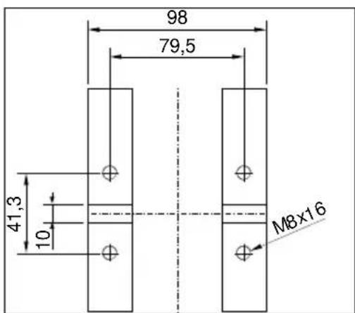
Fasten the gearing foot of the EBM 352/3 by means of four M 8 Allen screws to the drill rig. The drill stand should have a good stiffness and precise guide ways. The spindle of the machine needs to go parallel to the axle of the drill stand. Use only fall-safe drill rigs. It is advisable to use a water-collecting ring.
natural_image
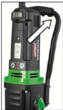
Close-up of a black and green industrial vacuum cleaner with a white arrow pointing to its side (no visible text or symbols)The EBM 352/3 is equipped with a transport handle which makes the transport of the core drill and inserting in the drill rig reception easier.
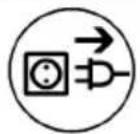
The EBM 352/3 is made in protection class I. In order to protect the operator, the machine can only be run with a GFCI. For this reason, the machine is standard equipped with a PRCD switch integrated in the cord which allows to connect the unit directly with a grounded socket.
Attention!

- The PRCD-safety switch must not lay in water.
- PRCD-safety switch must not be used to switch the tool on and off.
- Before you start working, check the proper functioning by pressing the TEST button.
First, check the correspondence of voltage and frequency and compare it with the data mentioned on the identification plate. Voltage differences from +6% to -10% are allowed.
Use only 3-wire extension cable with protecting conductor and a sufficient cross-section (min. 2.5 mm ^4 ). A cross-section which is too small could lead to excessive power loss and to overheating of machine and cable.
The machine is equipped with a start-up speed limiter to prevent fast expulsion fuses from unindented responding.
Water Connection
If the drill bit is not cooled enough with water, the diamond segments could heat up and consequently get damaged and weakened. For this reason, always make sure that the cooling system is not blocked.
In order to supply the machine with water, please proceed as follows:
- Connect the tool to the water supply system or a water pressure vessel using the GARDENA connector.
- Always make sure that the machine only runs with enough clear water as the seals get damaged when the machine is running dry.
- Attention! The maximum water pressure should not exceed 3 bar!
- Make sure that the segments are well cooled. If the drilling water is milky, the segments are well cooled.
- Overhead-drilling only with water collection ring.
- In case of frost warning, drain the water system.
Changing Gears

natural_image
Close-up of a green circular button with numbered labels (1, 2, 3) on a black surface, no readable text or symbols beyond labels.The EBM 352/3 is equipped with a mechanical 3-speed oil-bath gearbox. Select the speed according to the drilling diameter (ref. to the tool's identification plate). Use the speed selection to change to the next higher or lower speed until it locks. Change the speed only when the tool is not running; slightly turn the working spindle to ease the speed change.
Warning!

- Only change gears whilst the tool is not in operation!
■ Never apply force - Never use tools, such as hammers or pliers to change the gear.
Drill Bits
Diamond drill bits with an 1 14 " UNC female thread can be screwed directly onto the working spindle.
For drill bits with R 1/2" male thread, adapters are available as accessories.
Always use drill bits which match the material which has to be drilled.
You can prevent the machine from damage if you only use drill bits which are balanced and not deformed. Pay attention that diamond segments have enough relief cut towards the drill bit body.
Drill Bit Changing


Attention!
The machine is heavy and when you use or sharpen it, it might heat up enormously. You could burn your hands or get cut or ripped by the segments. Before the beginning of all works on the tool you have to disconnect the plug from the mains. Always use protective gloves when changing the drill bit.
The drill spindle has a right-hand thread.
To hold on spindle always use an jaw wrench SW 32.
Never remove the drill bit with impacts because this way the machine will be damaged. With some waterproof grease, which is put on the drill bit thread, and a copper ring between spindle and drill bit you can remove the drill bit easier.
Using the Drilling Unit
In order to operate safely, please observe the following instructions:
Safety at work:
■ Make sure that your work place is free of anything that might disturb your work.
■ Pay attention that your work-place is well-lit.
■ Make sure that you observe the conditions for the connection with the power supply.
- When laying the cables, make sure that it cannot be damaged by the tool.
■ Make sure that you always can overlook the work place in a sufficient way and that you always can reach all necessary control elements and safety devices.
- In order to avoid accidents, keep other persons away from your work place.
Required space for operation and maintenance
If possible, make sure that you have enough free space for operation and maintenance around the machine (about 2 metres). This way, you can work safely and in case of operating trouble you can intervene immediately.
Preparation
- When you drill into blocs, make sure that the blocs are well anchored and fixed.
■ Before drilling in supporting parts, make sure that you do not disregard the statics. Observe the instructions of the experts who are responsible for the design.
■ Make sure that you do not damage any gas mains, water mains or electric cables while drilling. - Pay attention that you do not touch any metallic parts of the machine when you drill walls and grounds where electric cables could lie under water.
- Pay attention that the drilling core does not hurt anybody or damaging anything when it drops out.
- If the drilling core might cause any damage when it drops out, use an device that can hold back the drilling core.
■ Make sure that the drill bit is well fixed. - Only use tools which are suitable for the particular material.
Fastening of the Drill Rig
The diamond core drill EBM 352/3 may only be used mounted on a drill rig. Since the drill rig is not included in the delivery, we point out some important kinds of assembly.
For this purpose, please refer to the drill rig's operating instructions.
Vacuum fastening:
For the vacuum, make sure that it is sufficient (minimum -0.8 bar). Make sure that the gaskets are not worn.
Attention! Do not use the vacuum fastening on the wall or overhead!
Please ensure that the leveling screws are adjusted in such a way that they do not protrude from the underside of the drill stand foot, otherwise the vacuum is affected and the stand may come away from its support.
Dowel fastening:
The most common way of fastening is dowel fixing.
If possible, use metal dowels only. The dowel diameter must not be smaller than 12 mm.
- In order to fasten the drilling unit correctly, you need the fastening set (order number 35721).
- Drill a hole with a diameter of 15 mm, 50 mm deep. Make sure that the hole is free of dust.
- Insert a dowel and open it with an expanding mandrel.
- Screw the thread rod into the dowel.
- Put the drilling unit with the deep hole in the base onto the thread rod.
- Place the washer and screw the butterfly nut very tightly.
- Adjust the drilling unit in the platform by using the four screws.
Drilling
Vertical drilling
- Switch the PRCD on.
- Open the water supply.
- Switch the motor on without touching the surface with the drill bit.
- Turn the handle to bring down the drill bit until it contacts the surface.
- In order to reach an exact centring of the drill bit, keep the feed low for the first centimeter of cutting depth.
- Then you can drill faster. A too small drilling speed reduces the power. On the other hand, when the drilling speed is too high, the diamond segments quickly become blunt.
Angular drilling
- Remove the screw in the foot base which arrests the column at 90^ .
- Loosen the two screws on the base of the column and turn the column to the requested angle.
- Retighten the screws again.
- At the beginning, it is better to drill very slowly because the bit only meshes with a fraction of its cutting area with the material. If you drill too fast or with a pressure which is too high, the bit can be off centre.
You have hit reinforced iron when you recognise while drilling that the feed rate gets very low, when you need to use more force, or when the water leaking from the bore hole clearly shows some metal chips.
Reduce the pressure on the drill bit to cut through the reinforced iron without any problems. You increase the pressure again when you have cut through the reinforced iron.
Drill bit extension
If you have to drill deeper than the usable length of your drill bit is:
- First, only drill to the point the usable length of the bit reaches.
- Remove the bit and pull the centre core out of the hole without moving the core drilling unit.
- Push the drill bit back into the bore hole.
Screw an adequate extension between drill bit and motor. If the collet of the drill bit is 1 14 , please do not forget the copper rings which make the removal of the drill bit easier.
Overload Protection
In order to protect the operator, motor and drill bit, the EBM 352/3 is equipped with a mechanical, electronic and thermal overload protection.
Mechanical: If the drill bit is suddenly blocked in the hole, a clutch will slip disengaging the drill spindle from the motor.
Electronic: To warn the user against overstressing the tool by applying to high feed force, a LED is mounted on the motor cap. It does not light during no-load run or at normal load. In case of over- load, the LED lights red. Now the tool must be discharged. In case of longer non-observation of the red indication, the electronics will independently cut the unit off. After discharge and switching the tool off and on again, you can continue working.
Thermal: In case of permanent overload, a thermocouple protects the motor against destruction. Here also, the user is warned by the overload indicator. Shortly before the maximum temperature is reached, the indicator flashes red. In that case, the tool switches off and can only be restarted after a certain cooling-down period (approx. 2 minutes). The overload indicator flashes until the machine has cooled sufficiently and can be used again. The cooling-down time depends on the temperature of the motor winding and ambient temperature.
Safety Clutch
The safety clutch should absorb shock and excessive stress. It is an aid and not an absolute protection. Therefore you have to handle and drill carefully. To keep it in good condition, the clutch should slip for a very short time (max. 2 seconds) in each case only. Slipping for longer periods destroys the safety clutch. After excessive wearing the clutch has to be renewed by an authorized service shop.
Fracture of Segments
If a diamond segment, parts of the reinforcement or something similar breaks out, and consequently the drill bit seizes, stop working on this bore and drill a hole with the same centre and a diameter being 15 – 20 mm bigger.
Do not try to finish your work using another drill bit of the same diameter!
After Drilling
When you have finished drilling:
- Pull the drill bit out of the hole.
- Stop the motor by using the motor switch and not the PRCD switch.
- Close the water supply.
Removal of the core when it sticks in the drill bit:
- Separate the drill bit from the motor (if possible).
- Put the drill bit in a vertical position.
- Knock carefully on the pipe by using a wooden hammer shank till the drilling core slips out. Never throw the drill bit against a wall by force or set about it with tools, such as hammer or jaw wrench. Otherwise, the pipe could go out of shape and neither the core can be removed nor the drill bit reused.
Removal of the core from blind holes:
Break off the core with a cotter or lever, or in pieces. Lift the core out with appropriate tongs or drill a hole in the core, screw an eyebolt in and pull the core out.
Care and Maintenance
Before the beginning of the maintenance or repair works you have to disconnect the plug from the mains!
Repairs may be executed only by appropriately qualified and experienced personnel. After every repair the machine has to be inspected by an electric specialist. Due to its design, the machine needs a minimum of care and maintenance. Regularly the following works have to be carried out or rather the component parts have to be inspected.
- Clean the drilling unit after having finished drilling. Later on, you have to grease the spindle thread. The ventilation slots always have to be clean and open. Pay attention that no water gets inside the core drill during the cleaning process.
- After the first 150 hours of operation you have to replace the gearbox oil. Gearbox oil changes bring about an essential increase of the tool's lifetime.
■ After approximately 250 hours of operation the carbon brushes have to be checked by a specialist and if necessary removed (only use original carbon brushes). - Have switch, cable and plug checked by an electric specialist quarterly.
Environmental Protection

Raw material recycling instead of waste disposal
In order to avoid damages on transportation, the power tool has to be delivered in sturdy packing. The packing as well as the tool and its accessories are made of recyclable materials and can be disposed accordingly.
The tool's plastic components are marked according to their material, which makes it possible to remove environmental friendly and differentiated because of available collection facilities.

natural_image
Simple line drawing of a trash bin with no text or symbolsOnly for EU countries
Do not dispose of electric tools together with household waste material!
In observance of European Directive 2012/19/EU on waste electrical and electronic equipment and its implementation in accordance with national law, electric tools that have reached the end of their life must be collected separately and returned to an environmentally compatible recycling facility.
The indication of noise emission is measured according to DIN 45 635, part 21. The level of acoustic pressure on the work place could exceed 85 dB (A); in this case protection measures must be taken.

Wear ear protectors!
The typical hand-arm vibration is below 2.5 m/s ^4 .
Measured values determined according to EN 60 745.
The declared vibration emission level represents the main applications of the tool. However if the tool is used for different applications, with different accessories or poorly maintained, the vibration emission may differ. This may significantly increase the exposure level over the total working period.
An estimation of the level of exposure to vibration should also take into account the times when the tool is switched off or when it is running but not actually doing the job. This may significantly reduce the exposure level over the total working period.
Identify additional safety measures to protect the operator from the effects of vibration such as: maintain the tool and the accessories, keep the hands warm, organisation of work patterns.
auto-stop brushes
In order to protect the motor, this power tool is equipped with auto-stop brushes. When the carbon brushes are worn out, the machine switches itself off.
In this case both brushes must be replaced at the same time with original brushes by an electrical specialist.
werden.
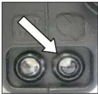
natural_image
Close-up of a mechanical component with two circular holes and a white arrow pointing to a feature (no text or symbols visible)In addition there is a service indicator on the motor cap, which indicates in advance that the machine is about to shut down due to worn carbon brushes. After the indicator lights up, you can use the tool for approximately 1 day. Then the carbon brushes should be replaced.
In case of breakdown, switch the machine off and disconnect the plug from the mains. Repairs on the electric parts of the tool may only be done by an electric specialist.
Trouble Shooting
| Error | Possible Cause | Error Recovery |
| machine does not work | mains current supply interruptedline cord or plug damagedswitch damagedthe PRCD-switch is off | plug in another electric appliance and check the functioninghave it checked by an electric specialist and replaced if necessaryhave it checked by an electric specialist and replaced if necessarypress RESET to switch on |
| motor runs, drill bit does not rotate | Gear not engaged properly or accidentally disengaged gearbox damaged | Operate the gear switch to engage the required gear have the tool repaired by an authorised service workshop |
| drilling speed too slow | drill bit damagedA too high water flow rate prevents self-sharpening of the drill bitdrill bit is blunt | check if drill bit is damaged and replace it if necessaryregulate the water quantitysharpen the drill bit with a sharpening block while using the flush |
| motor cuts off | the tool stopsthe tool overheats, overload protection of the motor has reactedcarbon brushes are worn out - auto-stop brush switch off | lead the tool in a straight mannerdischarge the tool and restart it by pressing the switch a couple of timesboth brushes must be replaced with original brushes by an electrical specialist |
| water drops out of the gearbox housing | shaft sealing rings damaged | have the tool repaired by an authorised service workshop |
Warranty
According to the general supply conditions for business dealings, suppliers have to provide to companies a warranty period of 12 months for redhibitory defects (to be documented by invoice or delivery note).
Damage due to natural wear, overstressing or improper handling are excluded from this warranty.
Damages due to material defects or production faults shall be eliminated free of charge by either repair or replacement.
Complaints will be accepted only if the tool was returned in non-dismantled condition to the manufacturer.
CE Declaration of Conformity
We declare under our sole responsibility that the product described under “Technical Data” is in conformity with the following standards or standardization documents:
EN 61 029, EN 55 014, EN 61 000
according to the provisions of the directives 2011/65/EU, 2004/108/EG, 2006/42/EG
Technical file (2006/42/EC) at:
Lothar Lässig
General Manager
25.04.2014

Frank Markert
Head of Engineering
FRANÇAIS
natural_image
Close-up of a black and green industrial vacuum cleaner with a white arrow pointing to its side (no visible text or symbols)natural_image
Close-up of a green circular button with numbered labels (1, 2, 3) on a black surface, no readable text or symbols beyond labels.natural_image
Simple line drawing of a trash bin with no text or symbolsnatural_image
Close-up of a computer control panel with two buttons and a white arrow pointing to one (no text or symbols visible)Lothar Lässig
General Manager
25.04.2014
Frank Markert
Head of Engineering
NEDERLANDS
natural_image
Close-up of a black and green industrial vacuum cleaner with attached hose and control panel (no visible text or symbols)natural_image
Close-up of a green circular button with numbered labels (1, 2, 3) on a dark surface, no readable text or symbols beyond labels.Waarschuwing!
natural_image
Simple line drawing of a trash bin with crossed lines indicating no waste or discharge (no text or symbols)natural_image
Close-up of a mechanical component with two circular buttons and a white arrow pointing to one (no text or symbols visible)Lothar Lässig
General Manager
25.04.2014
Frank Markert
Head of Engineering
Polski
Ważne wskazówki
natural_image
Close-up of a green and black industrial vacuum cleaner with a white arrow pointing to the handle (no visible text or symbols)natural_image
Close-up of a green circular button with numbered labels (1, 2, 3) on a black surface, no additional text or symbols visible.natural_image
Simple line drawing of a trash bin with no text or symbolsTyko dla krajów EU
natural_image
Close-up of a mechanical component with two circular holes and a white arrow pointing to one (no text or symbols visible)Lothar Lässig
General Manager
25.04.2014
Frank Markert
Head of Engineering
по-русски
natural_image
Close-up of a black and green industrial vacuum cleaner with a white arrow pointing to its side (no visible text or symbols)natural_image
Close-up of a green circular button with numbered labels (1, 2, 3) on a black background, no readable text or symbols beyond labels.natural_image
Simple line drawing of a trash bin with no text or symbolsnatural_image
Close-up of a mechanical component with two circular holes and a white arrow pointing to one (no text or symbols visible)Lothar Lässig
General Manager
25.04.2014
Frank Markert
Head of Engineering
Türkçe
Önemli Uyarılar
natural_image
Close-up of a green and black industrial vacuum cleaner with a white arrow pointing to the handle (no visible text or symbols)natural_image
Close-up of a green circular button with numbered labels (1, 2, 3) on a black surface, no readable text or symbols beyond labels.natural_image
Close-up of a mechanical component with two circular holes and a white arrow pointing to one (no text or symbols visible)Lothar Lässig
General Manager
25.04.2014

Frank Markert
Head of Engineering
Ihr Fachhändler Your distributor Votre marchand spécialisé Uw distributeur Wasz dostawca дилерами Stok yapan
natural_image
Mechanical device with green and black components, no visible text or symbolsDiamantbohrständer / Diamond Drill Rig / Support de perceuse Diamant Boorinstallatie / Statyw wiertnicy diamentowej
BST 352 V
DEUTSCH
natural_image
Close-up of a mechanical component with a curved arrow indicating rotation or adjustment (no visible text or symbols)natural_image
Black electronic device casing with visible internal components and mounting holes (no text or symbols)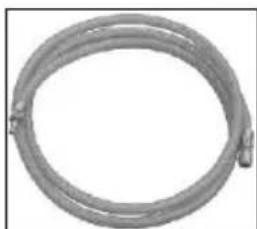
natural_image
Coiled metal pipe or hose with two connectors, no visible text or symbols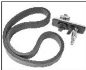
natural_image
Close-up of a black rubber strip with attached metal clip (no text or symbols visible)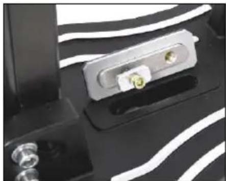
natural_image
Close-up of a mechanical component with metallic pins and a white wavy patterned surface (no visible text or symbols)Montage Vakuumset:
natural_image
Close-up of a mechanical component with a curved arrow indicating rotation or direction (no text or symbols visible)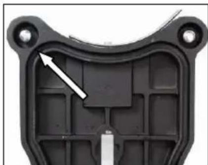
natural_image
Close-up of a black plastic mechanical component with a white arrow pointing to a specific area (no text or symbols visible)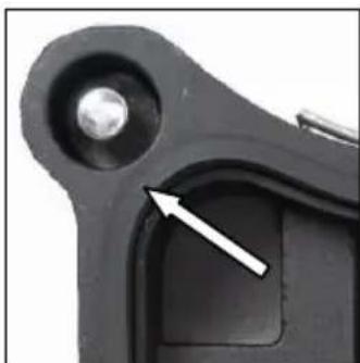
natural_image
Close-up of a mechanical component with a white arrow pointing to a specific part (no text or symbols visible)natural_image
Close-up of a mechanical component with a curved arrow indicating rotation (no visible text or symbols)natural_image
Close-up of a mechanical device with green and black components, no visible text or symbolsnatural_image
Close-up of a green industrial drilling rig with black and white components, no visible text or symbols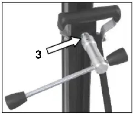
natural_image
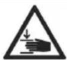
Green mechanical component with three circular features and two white arrows pointing to features (no text or symbols visible)Important Instructions
Warning symbols:
Warning: general precaution
Warning: dangerous voltage
Warning: hot surface
Tool, drill bit and rig are heavy – Caution: risk of squashing
Danger of tearing or cutting
During work you should wear goggles, ear protectors, protective gloves, and sturdy work clothes!
Wear ear protection
Wear safety goggles
Wear protective helmet
Wear protective gloves
Wear protective boots
Do disconnect from power before working on the tool!
Technical Characteristics
| Measures: 525 x 320 x 1040 mm | |
| Length of the column: 995 mm | |
| Weight: 22,5 kg | |
| Max. drilling diameter: 352 mm | |
| Inclination: 0° - 45° | |
| Carriage brake: Yes | |
| Locking in top position: Yes | |
| Fixture of the motor: Plate fixture by mounting plate | |
| Adaptation to surface: 4 positioning screws / 2 bubble levels |
Available special accessories:
| Item | Order no. |
| Fastening set (concrete) 35721 | |
| Fastening set (brickwork) 35724 | |
| Spare dowel 35722 | |
| Rawl – dowel 35725 | |
| Quick action bracing unit | 35730 |
| Water suction ring WR 352 | 35873 |
| Spare seal for water suction ring ED 352 for WR 352 | 3586L |
| Vacuum pump VP 04 | 09204 |
| Vacuum tube | 35855 |
| Vacuum set BST 352 V | 3585G |
Supply
Diamond drill rig with axle, turnstile, allen key and operating instruction in a cardboard box.
Application for Indented Purpose
The diamond drill rig BST 352 V is made for diamond core drills which are fixed by means of a mounting plate (e.g.: EBM 352).
The max. drilling diameter must not exceed 352 mm.
When drilling overhead, a water collecting device must be used.
In case of wrong handling or misuse, the producer does not assume any liability.
Use

After each readjustment always check that the screws are tightly fixed so that safe operating of the drill rig is possible.
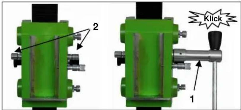
Mounting the turnstile
■ Mount the turnstile (1) on the right or left side of the carriage (2) depending on the work to be performed.
■ Check whether the turnstile (1) is fixed tightly.
Fastening of the Drill Rig
Hole centering indicator:
The drill rig is fitted with a hole centering indicator for easy and precise positioning.
natural_image
Close-up of a mechanical clamp or bracket with a curved arrow indicating rotation (no text or symbols visible)Mark the center of the hole to be drilled.
Fully extend the hole centering indicator (see fig.).
Position the drill rig in such a way that the tip of the indicator points precisely to the hole center mark.
After the drill rig has been fastened, put the hole center indicator back in its original position.
Fastening by means of dowels in concrete
To mount the drill stand by means of dowels it is necessary to remove the vacuum grip and the base gasket from the base plate.
■ Mark the position of the drill holes for the fastening on the surface to be drilled.
- Drill a hole (∅ 15) 50 mm deep (A), into which the dowel M12 (B) is to be placed; insert and secure the dowel with the doweling tool (C).
- Screw the quick action clamping screw (D) into the dowel.
For brickwork, Rawl-Dowels must be used (drillhole - ∅ 20mm).
- Install the drill rig.
- Fix the washer (E) and finally the fastening nut (F) on the quick action clamping screw (D).
- Tighten the fastening nut (F) with a wrench SW 27.
■ Before and after tightening the nut (F), the 4 adjustable screws have to be adjusted in order to adapt the rig to the surface.
Do check whether the drill rig is installed safely and firmly.
Fastening on the floor by means of vacuum
Don't use the vacuum mounting on the wall and overhead!
For a low-pressure mounting the surface where the base is mounted must be not porous and must be flat and free of cracks.
If this is not the case, this kind of mounting can't be used. For the vacuum mounting you need a vacuum pump, a vacuum hoses and the vacuum set BST 352 (see illustration). These items are available on request.
natural_image
Black electronic device with ports and connectors (no visible text or symbols)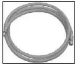
natural_image
Coiled metal pipe or hose with a looped end, no visible text or symbols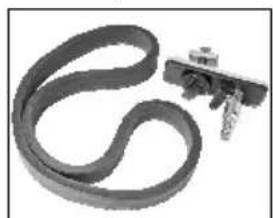
natural_image
Close-up of a black rubber band with a metallic clip attached (no text or symbols visible)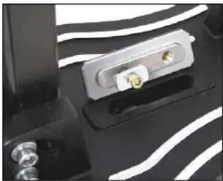
natural_image
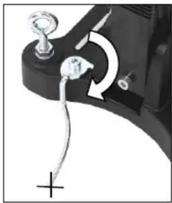
Close-up of a mechanical component with metallic pins and a black base, no visible text or symbolsFitting the vacuum set:
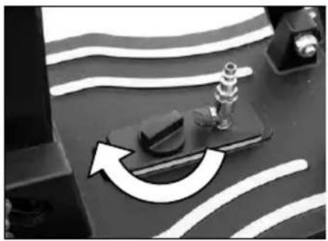
Position the coupling plate of the vacuum set on the drill rig base as shown.
Turn the knob 90° into the diagonal setting. This locks the coupling plate into the base.
Check that the coupling plate is secure.
Place the foam rubber seal into the recess on the bottom of the base.
natural_image
Close-up of a mechanical component with a curved arrow indicating rotation or motion (no visible text or symbols)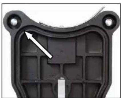
natural_image
Close-up of a black plastic mechanical component with a white arrow pointing to a specific internal feature (no text or symbols visible)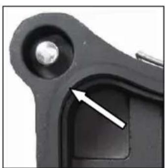
natural_image
Close-up of a mechanical component with a metallic sphere and a white arrow pointing to a specific area (no text or symbols visible)Please ensure that the levelling screw is adjusted so that it does not protrude from the bottom of the base, since otherwise the vacuum will be affected and the rig may come loose from the mounting surface.
When connecting the vacuum onto a sufficiently powerful vacuum (min. - 0.8 bar). make sure that the seals are not worn out.
Connect the drill rig and the vacuum pump by means of a vacuum hose.
Get the drill rig in the correct position, open the valve on the coupling plate and switch on the pump.
The vacuum pump must run during the whole working time and must be placed so that one can see the manometer.
Make sure that the drill stand is fixed firmly before you start drilling!
natural_image
Close-up of a mechanical component with a circular arrow indicating rotation (no visible text or symbols)To unfasten the vacuum connection, close the valve. This opens a bleed valve through which the vacuum can escape. Thus the rig can be activated if necessary when the vacuum pump is running.
Fastening by means of quick action bracing unit
In order to brace the drill rig by means of the quick action bracing unit, the distance to the opposite wall must be between 1.7 m and 3 m.
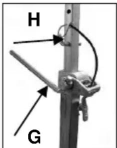
Position the drill rig. Position the quick action bracing unit as close as possible behind the support on the base of the rig. Fix the drill rig by turning the crank (G) clockwise. Secure in position by means of the appropriate bolt (H).
Attention!
It is important that the drill rig is firmly connected to the surface. If not fixed correctly, injuries to the operator or damages to the drilling unit may be caused. Uncontrolled movements during drilling will cause the drill bit to hit the surface to be drilled which may lead to a chipping of the segments. The drill bit might also tilt in the bore hole which consequently will damage it.
Fixing the Core Drill Motor

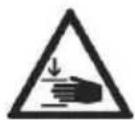

Caution! When mounting the machine, risk of squashing. Wear protective gloves!
Setting up the mounting plate
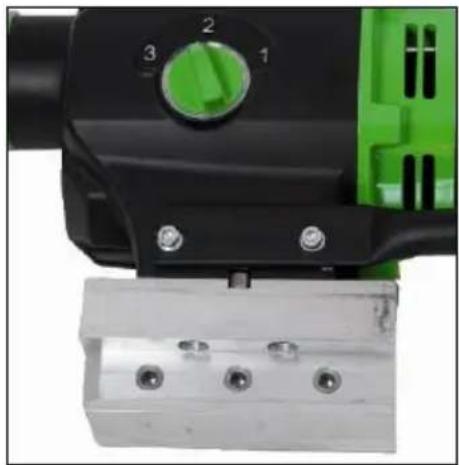
natural_image
Close-up of a mechanical device with green and black components, no visible text or symbolsMove the machine holder upwards until it locks in the top position.
Use the turnstile to open the locking device of the mounting plate.
Remove it and connect it to the core drill motor as described subsequently.
The tool is supplied with a mounting plate, a 10 mm fitting key and 4 Allen screws M8x20.
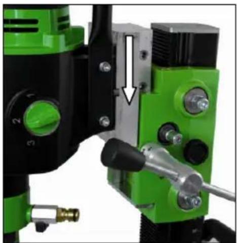
natural_image
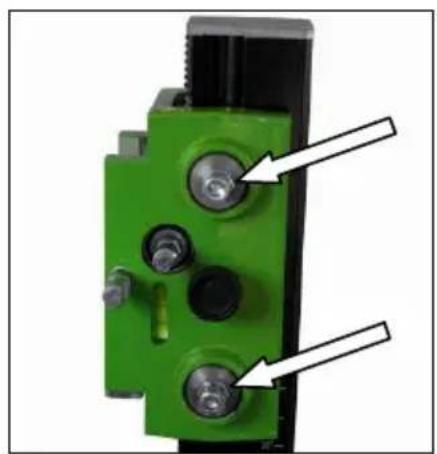
Close-up of a green and black industrial drilling machine with a white arrow pointing to a mechanical component (no visible text or symbols)The mounting plate is put on in such a way with the fitting key on the machine that the socket is in the mounting plate on the same side as the gear switch of the machine. Afterwards the four screws are insert and tightened firmly.
Insert the core drill with the attached mounting plate into the drill rig and lock it with the turnstile.
For the operation of the core drill, its operating instructions and safety advices have to be strictly observed!
Operations
In order to operate the tool safely, please observe the following notes:
Details of the work area
- Keep the work area free of everything which could obstruct operations.
■ Provide for adequate illumination of the work area. -
Adhere to the regulations concerning the power connection.
-
Lay the power cable in such a way that any damage by the drill can be avoided.
- Make sure to always keep the work area in view and to be able to reach all necessary operating elements and safety installations.
- Keep other persons away from your work area in order to avoid accidents.
Space requirements for operating and maintenance
Whenever possible, keep a free space for operating and maintenance of about 2 m around the drill position, so that you can work safely and have immediate access in case of a failure.
Drilling
At the beginning, drill very slowly, since the drill bit does only starts cutting with a fraction of the cut surface in the material. If you drill too fast or with too much pressure, the drill bit could get jammed.
Angled drilling
- Remove the screw (1), which locks the pillar at 90°.
- Loosen the two side screws (2) on the base plate.
- Loosen the clamp (3) on the support with the help of the feed lever.
- Now turn the column until the desired angle.
- Tighten the 2 screws (2) and the clamp (3) again.
The scale on the toothed column makes adjusting the drilling angle easier.

Drilling with Water
If you are cooling the drill bit with water a water collection ring is recommended. This will be mounted with a latch fastener on the screws of the base plate and ensures a clean drilling. Mainly for overhead or lateral drilling. (see spezial-accessories page 13).
Demounting the Core Drill Unit


- Move the machine holder with the core drill upwards until it locks in the final top position.
■ Remove the drill bit. - Loosen the locking of the mounting plate and remove the core drill machine from the drill rig (see page 17).
■ Loosen the fastening nut (F) (see page 15).
■ While doing so, hold the drill rig firmly! - Remove the drill rig.
- Unscrew the quick action clamping screw (D) (see page 15).
Care and Maintenance
- Always keep the drill rig clean, especially the column with the toothing and the 4 sliding balls in the machine holder. In order to allow the free movement of the pinion shaft, it should be slightly lubricated.
- In order to achieve a good performance of the drill rig, the 4 sliding balls in the machine holder have to move along the column without slackness.
Attention!
After every tenth drilling you should check if the sliding pieces have got loose-fitting due to drilling vibration.
If the position should have changed, it can be readjusted as follows:
natural_image
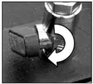
Close-up of a green mechanical component with three bolts and two white arrows pointing to features (no text or symbols visible)■ Loosen the counter nut on the Allen screw by means of an jaw wrench SW 17
- Adjust the Allen screws and the position of the sliding balls to the column by means of a hex head wrench SW 8.
- Tighten the counter nut again and check whether the carriage moves easily on the column
Behavior by Malfunction
Turn off the machine by malfunction and disconnect from the electricity network. Operations on the electrical system of the machine can be executed only by a specialist.
Trouble Shooting
| malfunction | possible cause | repair |
| Drill unit has to much play (vibration) | stand has been looseguidance has to much play thrust sliding balls | adjust the wing nutadjust guidance (see page 19)replace the sliding balls |
Warranty
According to the general supply conditions for business dealings, suppliers have to provide to companies a warranty period of 12 months for redhibitory defects. (to be documented by invoice or delivery note)
Damage due to natural wear, overstressing or improper handling are excluded from this warranty.
Damages due to material defects or production faults shall be eliminated free of charge by either repair or replacement.
Complaints will be accepted only if the tool is returned in non-dismantled condition to the manufacturer or an authorized Eibenstock service centre.
CE Declaration of Conformity
It is necessary that the machine (f. e. EBM 352/3) used in this drill rig comply with the requirements which are described in the specifications of the drill rig (f. e. drilling diameter, fixture of the motor).
We declare that this unit has been designed in compliance with 2006/42/EC. This unit must not be put into service until it was established that the Power Tool to be connected to this unit is in compliance with 2006/42/EC (identified by the CE-marking on the Power Tool).

natural_image
Close-up of a mechanical clamp or lever mechanism with a curved arrow indicating rotation (no text or symbols visible)natural_image
Black electronic device with exposed internal components and mounting holes (no visible text or symbols)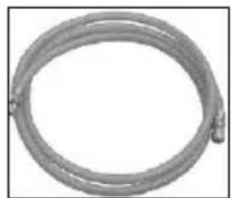
natural_image
Coiled metal pipe or hose with no visible text or symbols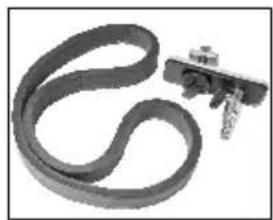
natural_image
Close-up of a black rubber band with a metallic clip attached (no text or symbols visible)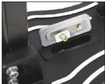
natural_image
Close-up of a mechanical component with metallic pins and mounting holes (no visible text or symbols)natural_image
Close-up of a mechanical component with a curved arrow indicating rotation or direction (no text or symbols visible)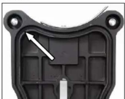
natural_image
Close-up of a black plastic mechanical component with a white arrow pointing to a specific internal structure (no text or symbols visible)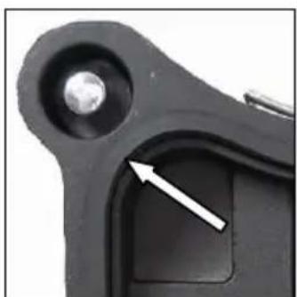
natural_image
Close-up of a mechanical component with a metallic sphere and a white arrow pointing to a section (no text or symbols visible)natural_image
Close-up of a mechanical component with a circular arrow indicating rotation (no visible text or symbols)natural_image
Close-up of a mechanical device with green and black components, no visible text or symbolsnatural_image
Close-up of a green and black industrial machine with a white arrow pointing to a component, no visible text or symbols.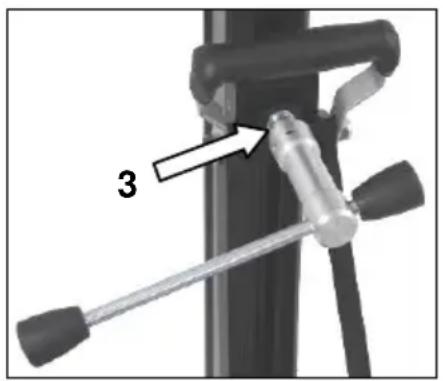
natural_image
Close-up of a green mechanical component with four bolts and two white arrows pointing to features (no text or symbols visible)natural_image
Close-up of a mechanical component with a curved arrow indicating rotation or adjustment (no text or symbols visible)natural_image
Black electronic device with visible ports and components (no text or symbols)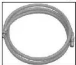
natural_image
Coiled metal pipe or hose with two connectors (no text or symbols visible)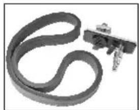
natural_image
Close-up of a black-and-white striped cable with a small mechanical component attached (no visible text or symbols)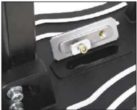
natural_image
Close-up of a black electronic component with white wavy lines and metallic connectors (no visible text or symbols)De vacuümset monteren:
natural_image
Close-up of a mechanical component with curved white lines and a black base, no visible text or symbols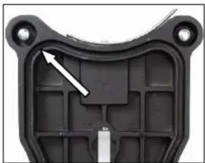
natural_image
Close-up of a black plastic mechanical component with internal cavities and mounting holes (no text or symbols visible)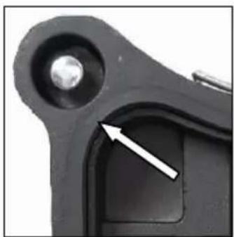
natural_image
Close-up of a mechanical component with a metallic bolt and a highlighted section (no text or symbols visible)natural_image
Close-up of a mechanical component with a curved arrow indicating rotation (no text or symbols visible)natural_image
Close-up of a mechanical device with green and black components, no visible text or symbolsnatural_image
Close-up of a green and black industrial machine with mechanical components and a white arrow indicating a adjustment or assembly (no visible text or symbols)natural_image
Close-up of a green mechanical component with multiple bolts and a black housing (no visible text or symbols)Założyć słuchawki
natural_image
Close-up of a mechanical component with a curved arrow indicating rotation or adjustment (no text or symbols visible)natural_image
Black electronic device casing with visible internal components (no text or symbols)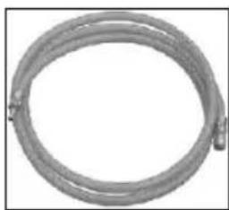
natural_image
Coiled metallic pipe with two connectors at ends (no text or symbols visible)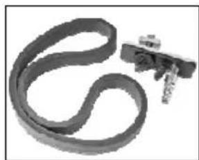
natural_image
Close-up of a black cable with a metallic clip attached (no text or symbols visible)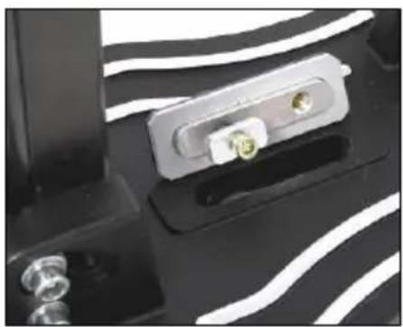
natural_image
Close-up of a mechanical component with metallic pins and a white wavy patterned surface (no visible text or symbols)natural_image
Close-up of a mechanical component with curved arrow indicating rotation or cycle (no text or symbols visible)
natural_image
Close-up of a black plastic mechanical component with a white arrow pointing to a corner detail (no text or symbols visible)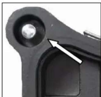
natural_image
Close-up of a mechanical component with a metallic spherical feature and an arrow pointing to it (no text or symbols visible)natural_image
Close-up of a mechanical component with a curved arrow indicating rotation (no text or symbols visible)natural_image
Close-up of a mechanical device with green and black components, no visible text or symbolsnatural_image
Close-up of a green and black industrial machine with a white arrow indicating a mechanical adjustment or assembly (no visible text or symbols)natural_image
Close-up of a green mechanical component with three bolts and two white arrows pointing to features (no text or symbols visible)


- Deutsch
- Wichtige Hinweise
- Nur für EU-Länder
- English
- Important Instructions
- Technical Data
- Supply
- Application for Indented Purpose
- Safety Instructions
- Pay attention that the tool is not exposed to directo rain.
- Fixing to Drill Rig
- Attention!
- Water Connection
- Changing Gears
- Warning!
- Drill Bits
- Drill Bit Changing
- Using the Drilling Unit
- Safety at work:
- Required space for operation and maintenance
- Preparation
- Fastening of the Drill Rig
- Vacuum fastening:
- Dowel fastening:
- Drilling
- Vertical drilling
- Angular drilling
- Drill bit extension
- Overload Protection
- Safety Clutch
- Fracture of Segments
- After Drilling
- Care and Maintenance
- Before the beginning of the maintenance or repair works you have to disconnect the plug from the mains!
- Environmental Protection
- Raw material recycling instead of waste disposal
- Only for EU countries
- Wear ear protectors!
- auto-stop brushes
- Warranty
- CE Declaration of Conformity
- FRANÇAIS
- NEDERLANDS
- Polski
- Ważne wskazówki
- Tyko dla krajów EU
- по-русски
- Türkçe
- Önemli Uyarılar
- Montage Vakuumset:
- Technical Characteristics
- Use
- Mounting the turnstile
- Hole centering indicator:
- Fastening by means of dowels in concrete
- Fastening on the floor by means of vacuum
- Don't use the vacuum mounting on the wall and overhead!
- Fitting the vacuum set:
- Fixing the Core Drill Motor
- Caution! When mounting the machine, risk of squashing. Wear protective gloves!
- Setting up the mounting plate
- For the operation of the core drill, its operating instructions and safety advices have to be strictly observed!
- Operations
- Details of the work area
- Space requirements for operating and maintenance
- Angled drilling
- Drilling with Water
- Demounting the Core Drill Unit
- After every tenth drilling you should check if the sliding pieces have got loose-fitting due to drilling vibration.
- Behavior by Malfunction
- De vacuümset monteren:
Brand : Eibenstock
Model : EBM 352/3
Category : Drill